
Introduction
It is nowadays well-established within the tribology community that the friction and wear response of a sliding system is governed by processes occurring at the sliding interface(s).[ Reference Godet 1 – Reference Scherge, Shakhvorostov and Pöhlmann 3 ] In sliding contacts of a hard surface against a ductile metal, these processes typically lead to the formation of third bodies, which consist of a tribofilm (e.g., mechanically mixed layer, oxide layer), transfer film (e.g., material transferred from one surface to the other), and debris particles surrounding and within the contact.[ Reference Blau 4 – Reference Rigney, Fu, Hammerberg, Holian and Falk 8 ] The tribofilm for most metallic sliding systems is commonly composed of a grain refined layer with increased oxygen, while the transfer film is material from the softer counterface transferred onto the harder one. While third body formation processes are studied extensively today, limited concrete correlations are found in the literature between the third body behavior and the fluctuations in the friction and wear of metallic sliding systems. This is mainly attributed to the fact that traditional tribology studies use ex situ techniques to understand the third bodies leading to the experimentally observed friction and wear response, primarily due to the confined nature of the buried interfaces, which makes it challenging to monitor.
With the intent to observe interfacial sliding processes, research has taken several approaches over the past few decades. In order to measure the film thickness of a lubricated contact in elastohydrodynamic and hydrodynamic conditions, in situ tribometry has been used for decades to perform interferometry measurements of the contact of a transparent disk and the sliding ball.[ Reference Gohar and Cameron 9 , Reference Marx, Guegan and Spikes 10 ] Similar in situ techniques, utilizing a transparent counterface sliding against a flat surface and/or Raman spectroscopy, have been employed to study transfer film formation processes of solid lubricants such as MoS2,[ Reference Dvorak, Wahl and Singer 11 , Reference Stoyanov, Strauss and Chromik 12 ] diamond-like carbon,[ Reference Chromik, Winfrey, Luning, Nemanich and Wahl 13 ] and other materials.[ Reference Muratore, Bultman, Aouadi and Voevodin 14 , Reference Voevodin, Muratore and Aouadi 15 ] Transparent counter bodies also allow to measure thermal distributions[ Reference Rowe, Bennett, Krick and Sawyer 16 ] or to make spectroscopic measurements.[ Reference Dvorak, Wahl and Singer 11 , Reference Strauss, Chromik and Hassani 17 – Reference Wahl and Sawyer 19 ] More recently, in situ tribometry has been used to directly observe the third body behavior of sapphire sliding unlubricated against aluminum and aluminum–alumina composite materials[ Reference Shockley, Descartes, Irissou, Legoux and Chromik 20 , Reference Shockley, Strauss, Chromik, Brodusch, Gauvin, Irissou and Legoux 21 ] as well as Cd and Zn–Ni coatings,[ Reference Sriraman, Strauss, Brahimi, Chromik, Szpunar, Osborne and Yue 22 ] and the third body behavior was correlated to friction events and wear. However, in situ tribometry has not yet been applied to understand the interfacial processes in boundary lubricated sliding between ductile metals, which are widely used in most industries, including automotive, aerospace, oil & gas, and sapphire.
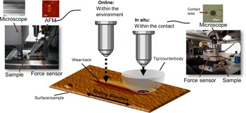
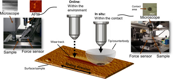
In the case of non-transparent counter surfaces, experimental setups exist that combine a tribometer and microscopy of the wear track. For instance, Keith[ Reference Keith 23 ] placed a rotating pin-on-disk tribometer underneath the objective lens of a scanning white light interferometer in order to measure the wear depth in sliding couples. Nowadays similar commercially available tribometers exist that allow to take a three-dimensional topography[ Reference Korres and Dienwiebel 24 ] or a Raman map outside of the contact in a discontinuous fashion. This approach has previously been referred to as the “within the environment” or online method, in contrast to the “within the contact” or in situ technique using a transparent counterface.[ Reference Sawyer and Wahl 25 ]
In this study, we combine both techniques in order to obtain a better understanding of the interfacial processes in lubricated metallic sliding contacts and furthermore to compare the experimental data that can be gathered with the two methods. We use sapphire as a counterface and pure aluminum as a substrate to show the competency of this approach. The changes in the chemistry, transfer film, and topography observed with these methods are then correlated to fluctuations in friction and wear. Then, a stress analysis is performed to provide insights on the microstructural changes near the surface.
Experimental methods
Tribology experiments are performed using two different approaches: “within the environment” and “within the contact” (Fig. 1). The first approach is realized using an online tribometer, equipped with a friction force sensor, a digital holographic microscope (DHM) (LyncéeTec SA DHM R2100, Switzerland) allowing for quantitative measurement of the surface topography by monitoring of topographical changes after each cycle. The DHM permits surface profiling at a high acquisition rate of up to 15 images/s because it does not need to use vertical scanning. A 50 × immersion lens is used with the holographic microscope in order to measure the wear and roughness after each cycle; using the DHM, topographical changes of one section of the sliding track are recorded just after the counter surface has passed. The roughness values are obtained using a 20 × 20 µm2 spot on the worn and unworn surfaces. The force sensor consists of three SKL 1417-IR (Tetra GMBH, Germany) fiber optic sensors (FOS). More details on this approach can be found elsewhere.[ Reference Korres and Dienwiebel 24 ]
Schematic representation of the two different experimental methods for studying the interfacial processes in sliding couples.

The “within the contact” approach is realized in this study using the in situ tribometer equipment. The instrument is custom-built to allow for video microscopical investigations of the sliding interface through a transparent hemispherical counterface. The generic design of the instrument is based on an experimental setup first described by Descartes and Berthier,[ Reference Descartes and Berthier 26 ] subsequently demonstrated in detail by various authors in the groups of Singer and Wahl[ Reference Chromik, Winfrey, Luning, Nemanich and Wahl 13 , Reference Singer, Dvorak, Wahl, Scharf, Dowson, Priest, Dalmaz and Lubrecht 18 , Reference Chromik, Baker, Voevodin and Wahl 27 – Reference Scharf and Singer 29 ] and Chromik et al.[ Reference Stoyanov, Strauss and Chromik 12 , Reference Wahl and Sawyer 19 – Reference Sriraman, Strauss, Brahimi, Chromik, Szpunar, Osborne and Yue 22 , Reference Chromik, Strauss and Scharf 30 , Reference Shockley, Descartes, Vo, Irissou and Chromik 31 ] Birefringence from the sapphire is eliminated by inserting a polarizing film into the light path. Video microscopy is conducted through the counterface to examine third body formation and transfer film dynamics. Videos are captured using a commercially available camcorder with a pixel resolution of 853 × 480 at 29.97 frames/s. The use of a 10× ultra-long working distance objective lens allowed for resolving 1.2 µm/pixel.
The experiments using both techniques are performed on a 99.9 wt.% pure aluminum plate obtained from Goodfellow GmbH in the “as rolled” condition and surface polished to a rms value of 50 nm. The counterface is a hemispherical sapphire counterface with a radius of 3.175 mm and the lubricant used is hexadecane. Cross-sectional scanning electron microscope (SEM) images obtained from focused ion beam (FIB) cuts of the sample prior to the sliding experiments reveal that the polishing procedure does not have a significant influence on the near-surface structure. The sliding experiments in both methodologies are performed using a sliding velocity of 20 mm/s and the initial normal load is 2 and 8 N. Sample characterization and ex situ analysis of the worn surfaces is performed using x-ray photoelectron spectroscopy (XPS) (PHI 5000 VersaProbe, Physical Electronics Inc. and an Axis Nova, Kratos Analytical) in order to observe chemical changes at the surfaces and subsurfaces. XPS (PHI 5000 VersaProbe) depth profiles are plotted in terms of sputtering depth, which is estimated based on depth calibrations with SiO2. A sputtering time of 10 min can be estimated to be approximately 20–30 nm.
Results and discussion
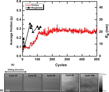
The friction behavior of the experiment performed with the online tribometer (i.e., using an initial load of 2 N initial normal load) is shown in Fig. 2. For the first 50 cycles, the coefficient of friction is approximately 0.1. Subsequently, it increases up to ~0.3 at about 100 cycles, where it remains nearly constant throughout the remainder of the sliding test. This behavior is typical for ceramic/metal sliding contacts[ Reference Stoyanov, Romero, Järvi, Pastewka, Scherge, Stemmer, Fischer, Dienwiebel and Moseler 32 , Reference Stoyanov, Merz, Romero, Wählisch, Abad, Gralla, Stemmer, Kopnarski, Moseler, Bennewitz and Dienwiebel 33 ] and has been previously reported for aluminum.[ Reference Shockley, Strauss, Chromik, Brodusch, Gauvin, Irissou and Legoux 21 ] One benefit of using an online tribometer is the capability of measuring the roughness within the wear track throughout the different sliding cycles, which is plotted accordingly in Fig. 2. The average roughness follows the trend of the coefficient of friction relatively closely, where it is low in the beginning and increases within the first few cycles. Correspondingly, the topography images of the worn surface at the various sliding cycles are shown in Fig. 2(b). Narrow grooves parallel to the sliding are observed within the first few cycles of the experiment (up to the 45th cycle) when the friction coefficient is relatively low. This behavior during the running-in stage has been previously observed for metal/ceramic tribocouples and is denoted as adaptation of the surface topographies at the sliding interface. Typically the asperities of the harder material (i.e., alumina and/or transferred, work hardened aluminum) plow through the surface of the softer material (i.e., pure aluminum) generating the grooves parallel to the sliding direction.[ Reference Buckley 34 ] Subsequently, the wear track grew wider and the grooves become less evident. Instead, the wear track is significantly rougher with notably higher amount of debris particles. The higher roughness of the wear track and the formation of debris particles correlate well with the increase in friction, which indicates activation of additional mechanisms (i.e., in addition to plowing).
(a) Friction and roughness (R a) behavior measures using “within the environment” approach and (b) online images of the wear track.

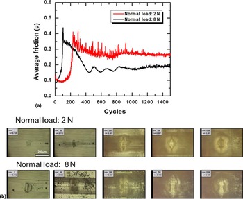
While the online tribometer reveals information on wear track morphology, the in situ approach directly observes the sliding contact, making the two techniques complementary. The friction coefficient of the experiment performed with this tribometer for two different normal loads (2 and 8 N) is shown in Fig. 3. At 2 N (i.e., the same normal load as the online tribometer experiments), as expected, the friction behavior is similar to the one obtained with the online tribometer; initially the coefficient of friction is low at ~0.1 after which it increases to above 0.3. Subsequently, it decreases slightly to around 0.3, where it remains constant for the remainder of the test.
(a) Friction behavior measured using the in situ tribometer and (b) in situ micrographs of the contact during sliding.

The in situ images of the contact area for the corresponding cycle number are shown in Fig. 3(b). When the coefficient of friction is low in the beginning of the experiment (i.e., cycle # 1), nearly no transfer film is observed. However, once the coefficient of friction begins to increase at around 50 cycles, some aluminum transfer is found on the counterface. Consequently, upon further sliding, more material is transferred onto the counterface within the contact area as well as surrounding the contact in the form of debris particles. Subsequently, the friction coefficient increases to above 0.3 and then decreases to approximately 0.3 where it remains for the remainder of the test.
Interestingly, the experiment with the higher normal load (8 N) showed a different behavior; while the friction coefficient (COF) is below 0.1 upon initial sliding, it increases to above 0.4 at an earlier stage compared with experiment with a 2 N normal load. After approximately 100 cycles the COF drops below 0.2 and it remains there for the remainder of the experiment, which is clearly lower compared with the experiment with an 8 N normal load. The different friction behavior with the two normal loads correlates well with the deviation of the in situ visual observation of the contact, as shown in Fig. 3(b). For the experiment with an 8 N normal load, a transfer film is formed within the first few cycles, which increases in size with the increase in contact area, as seen with the image of the 30th cycle. In parallel, the friction increases to a value above 0.4. At the 100th cycle, however, nearly no transfer is observed on the contact area and congruently the friction coefficient drops below 0.2. Similarly, the in situ images at higher cycle numbers show nearly no transfer film in the center of the contact area, which correlates well with the low friction.
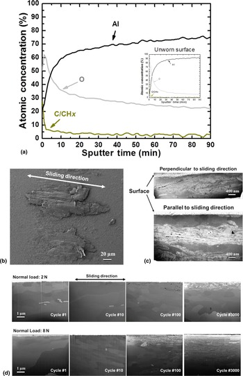
Chemical and structural ex situ analyses of the third bodies are performed to determine their influence on the friction behavior. The XPS analysis of the worn aluminum surface as a function of the sputtering depth is shown in Fig. 4(a). The insert of the figure presents the analysis of the unworn surface as a comparison. The analysis clearly shows an increase in the oxide content near the surface subsequently to wear. While the oxygen content slightly decreases with respect to the sputtering depth, it remains above 20 at.% at 160 nm. In comparison with the unworn surface, the oxygen content drops below 20 at.% at around 20 nm from the surface, as shown in Fig. 4(a). Such an increase in the oxide content is common for metallic sliding contacts and has been previously reported for Al alloys.[ Reference Shockley, Strauss, Chromik, Brodusch, Gauvin, Irissou and Legoux 21 ] It should be noted that some carbon is also detected on the surface of the worn aluminum, which is not as evident on the unworn surface. This carbon layer on the surface has likely formed from the hexadecane during sliding.
Ex situ analysis of the contact using (a) XPS, (b) top-down SEM image of the counterface, (c) cross-sectional SEM imaging of the transfer film, and (d) cross-sectional SEM images of the subsurface region after the 1st cycle, 10th cycle, 100th, and 3000th cycle.

Typical SEM image of the transfer film after sliding with a 2 N normal load is shown in Fig. 4(b). The corresponding cross-sections of the transfer film observed in Fig. 4(b), developed with a FIB, are shown in Fig. 4(c). The upper portion of the figure shows the cross-section of the transfer film parallel to the sliding direction, while the lower portion shows the cross-section of the transfer film perpendicular to the sliding. Based on the long gaps (cracks) in the parallel direction to the sliding, it is possible that the transfer process is based on a layer-by-layer buildup, as has been observed for high purity and commercial purity aluminum previously and attributed to shear banding during sliding.[ Reference Kuo and Rigney 35 ] The cross-sections clearly show grain refinement near the surface with a significant amount of cracks and defects. Such grain refinement is common during sliding contacts and has been reported on numerous occasions for Al alloys[ Reference Shockley, Descartes, Irissou, Legoux and Chromik 20 , Reference Shockley, Strauss, Chromik, Brodusch, Gauvin, Irissou and Legoux 21 , Reference Stoyanov, Linsler, Schlarb, Scherge and Schwaiger 36 ] and is typically attributed to nucleation of dislocation and rotation of clusters.[ Reference Rigney 6 , Reference Fischer 37 ] To study the grain-refinement evolution, the microstructures of the aluminum at various cycle numbers are shown in Fig. 4(d) and correspond to the surface from the in situ sliding tests. Upon initial sliding (i.e., first cycle), some grain refinement near the surface is observed, although it is minimal and could have also been caused by the polishing process. The grain refinement near the surface becomes more evident at the 100th cycle, where the friction coefficient started to increase. During steady state, the fine-grained structure is clearly visible and interestingly a significant amount of voids and have accumulated within ~1 µm of the surface. These structures were also observed in experiments using copper as a substrate and could be caused by folding events.[ Reference Beckmann, Romero, Linsler, Dienwiebel, Stolz, Moseler and Gumbsch 38 ] The experiments with the higher normal load (8 N) exhibit a slightly different behavior; evident grain refinement is already observed after 100 cycles following the trend of the friction coefficient, which increases earlier compared with the test with the lower normal load. In addition, the fine grained layer here remains thicker during steady state compared with the experiment with a 2 N normal load.
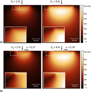
To elucidate on the mechanisms leading to the near-surface microstructural change, we evaluate the stress fields underneath on the aluminum sample. The analysis is based on Hamilton's set of equations for substrate stresses under sliding contact[ Reference Hamilton 39 ] and has also been used more recently on sliding wear of Ni–W alloys.[ Reference Rupert and Schuh 40 ] In our study, we use Hamilton's set of equations with the following inputs: Young's moduli of Al (70 GPa) and sapphire (300 GPa); Poisson's ratios of Al (0.3) and sapphire (0.22); the friction coefficient μ = 0.27. Figure 5(a) shows the resultant stress distribution underneath the contact with an applied normal load of 2 N for a stationary and a sliding case. In the stationary condition, the stress distribution results in the Hertzian model for sphere on flat contact and increases with increasing the normal load from 2 to 8 N. As expected, the stress distribution underneath the contact changes when a tangential force is added, such that the region with the maximum stress shifts toward the direction of the tangential force and an additional stress behind the contact appears. These observations become more evident with the higher coefficient of friction, as shown in Fig. 5(b). In addition, closer observation of the contact with a tangential force reveals that the highest contact stress is at the contact surface. Insets in Figs. 5(a) and 5(b) show that with friction the highest stresses are observed within 1 µm of the surface, which indicates that this region experiences a high degree of plasticity.
Subsurface stress analysis using Von Mises stresses for (a) static contact and (b) with friction.

This analysis correlates well with the experimental observations; the experiments with a 2 N normal load showed that the highest degree of deformation occurred within 1 µm below the surface. Similarly, the experiments with the higher normal loads showed a thicker grain-refined region, which is consistent with the larger stress area below the surface as observed with the von Mises stress calculations. A similar behavior has been previously reported with aluminum–silicon alloys, where the higher contact stress leads to a shorter running-in period and a lower steady-state coefficient of friction.[ Reference Stoyanov, Linsler, Schlarb, Scherge and Schwaiger 36 ] Similarly, in the study on pure aluminum, the running-in stage for the higher normal load is shorter compared with the experiment with the lower normal load. One aspect that was not captured in the previous study was the difference in the transfer film behavior between the different contact stresses. The in situ tribometry in this study showed that the experiment with the higher contact stress resulted in more aluminum transfer initially, which then detached from the counterface and consequently lowered the friction during steady state. Interestingly, no further transfer is observed from the aluminum onto the counterface, possibly due to the high degree of plastic deformation and increased oxide content, which could cause strengthening and surface passivation.
Conclusion
We combine “within the environment” and “within the contact” in situ tribometery to study the interfacial processes in lubricated metallic sliding contacts. The “within the environment” technique is realized using an online tribometer directly observing the evolution of the wear track, while the “within the contact” technique is realized using an in situ tribometer directly observing the sliding contact. This combined approach allows for linking changes in the friction to changes in the topography and third body (e.g., transfer film, debris particles) behavior. The results show that friction behavior of sapphire sliding against pure aluminum is in in good agreement between the in situ and online methodologies, revealing initially a running-in phase followed by steady-state sliding with a higher friction coefficient. The online approach showed that the evolution of the roughness follows the trend of the coefficient of friction closely. Similarly, the transfer film behavior observed with the in situ technique correlate well with the roughness of the worn surfaces and the subsurface microstructure of the worn aluminum. In addition, the effect of normal load on the running-in behavior is also studied in terms of differences in the interfacial processes. The difference in the running-in behavior is then correlated to the difference in the subsurface microstructure and transfer film behavior, which is attributed to the different stress fields.
Acknowledgments
PS and MD thank the Deutsche Forschungsgemeinschaft for financial support. RRC and JMS thank the Natural Science and Engineering Research Council (NSERC) of Canada for financial support. MD also acknowledges support from COST action MP 1303. The authors would also like to thank Patrice Brenner and Eberhard Nold for their contributions with the FIB and XPS analyses, respectively. The authors also thank Markus Stricker for his help with the online measurements.