I. INTRODUCTION
Since their inception in 2004, high-entropy alloys (HEAs) have generated a huge level of interest and research throughout the world, with over 2000 articles published in this area by the end of 2017. The original concept, as outlined by Yeh et al.,Reference Yeh, Chen, Lin, Gan, Chin, Shun, Tsau and Chang1 was to create alloys through near equiatomic mixtures of five or more elements (each with concentrations between 5 and 35 at.%) rather than simply basing them on a single principal element. It was believed that the properties of these multicomponent alloys might be superior to those typically found in conventional single element-based alloys. As part of this proposal, four core principles were outlined that underpinned the special nature of these new alloys: (i) their high-entropy would enhance solid solution formation, (ii) diffusion in these solid solutions, and thus phase transformations, would be significantly slower than in conventional alloys due to lattice distortion and the cooperative diffusion of elements, (iii) the lattices of these materials would be highly distorted because all atoms are solute atoms and their atomic sizes are all different from one another, and (iv) the superior properties were a result of a ‘cocktail effect’.Reference Yeh2 These four concepts have been the topic of much debate in the HEA literature, but over time their fidelity has been questioned and, as highlighted in two critical reviews published in 2016,Reference Pickering and Jones3,Reference Miracle and Senkov4 these alloys appear to conform to conventional metallurgical principles.
However, the concept of a highly strained lattice remains of interest as there is very little dedicated research looking directly at this effect. One reason for this apparent gap in the literature is the difficulty in experimentally investigating the distortions of the lattice,Footnote a but it is of critical importance, as this concept has implications for the solid solution strengthening of all alloys. As such, the topic is of great importance not only to those working on HEAs but also to the broader metallurgical community.
With this in mind, the current article, which represents the first dedicated consideration of this concept, presents a detailed review of the proposed lattice distortions in HEAs through four main thematic sections. The first of these outlines the background theory related to the concept, including an overview of the different types of strains that can exist in a material and the thermodynamic consequence of a highly distorted lattice. Having established what is meant by local lattice strain, the second section introduces experimental techniques capable of providing information on a suitable length scale. The way in which such local lattice strains will manifest themselves in the acquired data will be discussed, together with a consideration of any specific advantages or limitations relating to each technique. In the third section, the existing literature that directly relates to the assessment of local lattice distortions in HEAs is critically reviewed, to establish what is actually known about the nature of multicomponent solid solution crystal structures. The final section provides some general conclusions and observations that arise from the preceding discussion and lays out some key questions that need to be addressed by the HEA community moving forwards.
At this stage, it should be noted that this review will make no consideration of data that provide only indirect or inferred evidence of a severely distorted crystal structure, such as the link commonly made from mechanical property data.Reference Yeh2,Reference Wang, Zhang and Chen5 The reason for this exclusion is two-fold; first, such measurements do not unambiguously show the lattice to be highly strained, nor can they quantify the magnitude of the strain.Reference Miracle and Senkov4 Second, many HEAs initially reported to be single-phase solid solutions have, upon further study with more advanced techniques, been shown to have multiphase microstructures with fine-scale, sometimes ordered, precipitates.Reference Pickering and Jones3,Reference Pickering, Stone and Jones6 Consequently, determining the magnitude of solid solution strengthening in these materials from mechanical property data becomes significantly more complex and increasingly unreliable, as their strengths will be dependent on all available mechanisms (e.g., precipitate strengthening and ordered hardening), which would need to be separated. Thus, considering such data serves only to confuse an already complex situation rather than clarify it.
II. CONCEPT AND BACKGROUND THEORY
A. Types of strains
Metallurgical and crystallographic literature commonly uses the term ‘strain’ to cover several different types of distortions or change within a structure and, therefore, it is worth clarifying their use here to prevent future confusion. This is of particular importance in the field of HEAs, where within the existing literature, there are numerous examples of incorrectly attributed strains.
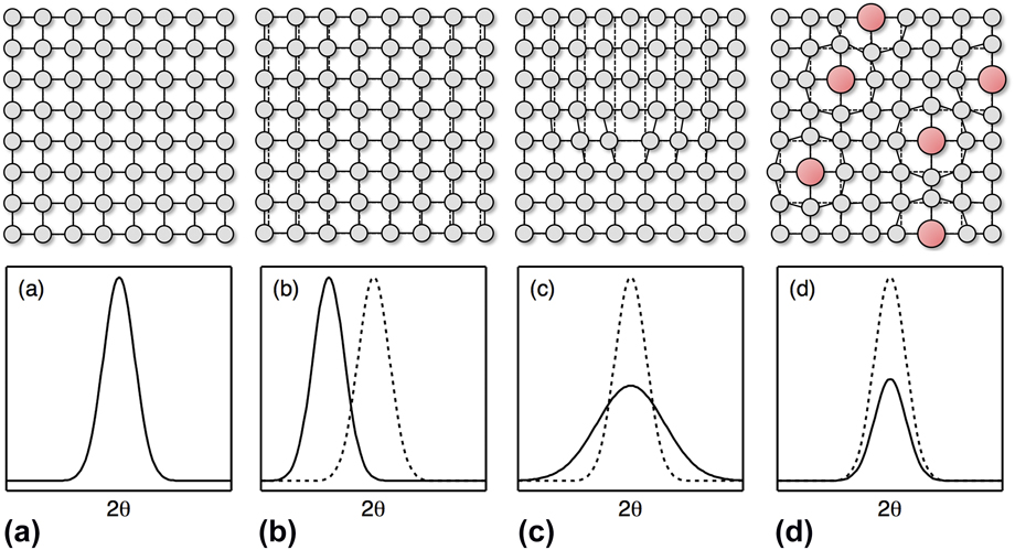
Broadly speaking, there are three types of strains that are conventionally defined, which tend to be distinguished by either the cause of the displacement or by the length scale over which the strain acts.Reference Withers and Bhadeshia7 It is important to recognize how each type of strain would manifest itself in experimental data. Therefore, information as to how each strain type influences diffraction data is also included, as this represents the technique most widely utilized to study strains. Since these points are so fundamental to this entire research area, schematic diagrams illustrating how the different types of strain influence the observed diffraction data are provided in Fig. 1.
Schematic illustrations of the variations in Bragg peaks caused by the different types of strain exhibited by the lattice of a single crystal. In each case, the black line shows the new peak and the dotted line shows the reference peak for an ideal undistorted structure. (a) An ideal undistorted structure. (b) Bulk strain producing a change in the overall interplanar spacing, resulting in an angular shift of the Bragg peak. This would be representative of both Type I and Type II strains in a single crystal. (c) Type III strain caused by changes in the interplanar spacing around planar defects such as dislocations. This results in a broadening of the Bragg peak (particularly at high angles). (d) Static off-site displacements caused by point defects (e.g., substituted larger red atoms) in the structure. This local lattice strain results in a decay of the Bragg peaks (particularly at high angles) and a reduction in the peak intensity.

Type I strains are macroscopic and are near homogenous over large distances, which are often at a length scale equivalent to an entire sample or component. Examples of such strains include the response to bulk applied stresses, where all of the crystals within the material are deformed in a common direction. Consequently, diffraction data relating to the deformation axis of a specimen, e.g., from planes aligned such that the plane normals are parallel to the applied stress, would exhibit a similar effect, with the interplanar spacings of all reflections either increasing or decreasing in line with the applied stress.
Type II strains act over shorter distances than Type I strains and vary within a specimen on the length scale of the microstructure.Reference Dye, Stone and Reed8 These intergranular strains typically evolve as a result of crystallographic anisotropy and, thus, represent the variation in the response of grains of different orientations to a given applied stress. As such, these strains manifest themselves as inhomogeneous alterations in the interplanar spacings of each reflection in a diffraction pattern.
Type III strains act over a shorter length scale still and correspond to the variations that can occur within a crystal itself. These strains result from local perturbations in the long-range lattice structure caused by the stress fields around crystal defects such as dislocations or discontinuities in atomic registry at interfaces. The small alterations in interplanar spacings as a result of these strains also influence the diffraction conditions leading to a broadening of a diffraction peak as a wider angular range gives rise to constructive interference.
Despite these three definitions covering a broad range of different strains, the displacements arising at the atomic level due to alloying effects are distinct and, as such, need to be considered independently. Since the concept of a highly distorted lattice structure is central to the founding principles of the HEA field, it is critical to consider it here.
If a defect free, pure crystal is considered; then, ignoring thermal movements, all the individual atoms within the crystal would be located on the ideal atomic positions defined by its unit cell. As such, the interatomic distances between coordinated atoms would be constant. This situation is commonly visualized through the hard sphere model. The incorporation of a secondary atom, with a different atomic radius, into this host lattice causes a local distortion, as neighboring host atoms are displaced from their ideal positions by the mismatch in atomic size. In the case of substitutional incorporation, as would be the case in HEAs, the displacement of the neighboring host atoms would be isotropic.Footnote b This concept is widely accepted and forms the basis of our understanding of solid solution strengthening in all alloys, as the strain field of a gliding dislocation interacts with that of the substituting atom. To facilitate the following discussion, the static displacement of an atom away from its ideal position will be referred to as local lattice strain, although it could also be considered as an addition to the types of strains previously defined and, as such, would represent a Type IV strain.
At this point, it should be appreciated that in any real crystal, considered at a given temperature, the constituent atoms will be displaced from their ideal locations due to thermal oscillations. If a pure, defect-free crystal is considered, then these oscillations are centered about the ideal location and, therefore, if considered over a period of time, the average position of the atom is coincident with the ideal location. As such, the dynamic displacements associated with thermal motion are not considered a form of local lattice strain. By contrast, in a crystal that contains static displacements, e.g., a solid solution, the thermal oscillations will occur around the displaced location rather than the ideal position. Thus, the instantaneous location of any atom will be a convolution of the static and dynamic displacements.
B. HEAs
The original HEA concept was a material that consisted of five or more elemental species in near equiatomic concentrations. It might have been expected that these multi-element combinations would produce microstructures that contained multiple phases, but early observations found that such alloys could exist as single-phase solid solutions. Conventionally, the formation of multiple phases is understood as the point at which the enthalpic contribution to Gibbs energy dominates the entropic contribution. Therefore, the apparent formation of stable multi-element equiatomic solid solution phases was rationalized by the suggestion that their entropy of mixing was large and, therefore, dominated the Gibbs energy even at low temperatures.
The observation of multi-principal element alloys existing as solid solutions explicitly means that individual atoms are randomly distributed across all the lattice sites in a single crystal structure. Since these species all have a different atomic radius, it was suggested that their incorporation into a single structure would result in a larger number of atoms being statically displaced from their ideal positions (local lattice strain), than would be found in a compositionally simpler solid solution phase. Consequently, it was expected that the resulting structure would be highly distorted, Fig. 2, giving rise to its definition as an HEA core principle.Reference Yeh2 It should be noted that these distortions are not sufficiently large to disrupt the long-range average structure of the crystal as demonstrated by the presence of Bragg peaks in the corresponding diffraction pattern, i.e., the HEA remains crystalline and does not become a bulk metallic glass.
Schematic illustration of an ideal monatomic material and an HEA (after Yeh et al.Reference Yeh61). Colored spheres, with different atomic radii, indicate individual atomic species.

However, the occurrence of these local lattice strains is energetically unfavorable and, as such, their presence will adversely affect the stability of the solid solution. The relationship between solid solubility and local lattice strain is not a new concept, as shown by the work of Hume-Rothery et al. on binary alloys.Reference Hume-Rothery, Mabbott and Channel Evans9,Reference Hume-Rothery, Smallman and Haworth10 From a consideration of a wide range of binary alloys, four key factors were identified, all of which needed to be satisfied in order for extensive solid solubility to occur. Of particular interest to the present discussion is that of a maximum tolerable difference in atomic size between the two species. It has been shown that the vast majority of binary combinations do not show appreciable solid solubility if the difference in atomic radii is greater than 15%.Reference Hume-Rothery, Smallman and Haworth10,Reference Waber, Gschneidner, Larson and Prince11
It is, therefore, expected that as the lattice strain increases, so a solid solution will become less thermodynamically stable and the system is likely to decompose into multiple phases. This naturally leads to the question of what level of strain can be tolerated by these higher order solid solution alloys and, further, what is the resulting strengthening effect that will be provided by such strains?
The observed level of lattice distortion will also be affected by the relaxation of the structure. It is commonly understood that the substitution of larger elemental species into a host lattice will cause an expansion of the structure. In binary alloys, such expansion is commonly referred to as Vegard’s law, which describes a linear dependence of the lattice parameter with increasing solute content. Similar effects are experimentally observed for higher order systems, although Vegard’s law is often observed to break down. Further relaxation of the overall lattice may serve to reduce strain in the system and provide thermodynamic stabilization. As such, experimental data is the only way to obtain evidence of the magnitude of the local lattice strains in these relaxed structures.
III. METHODS OF ASSESSING LOCAL LATTICE STRAIN
To accurately assess the local lattice strains of a material, it is necessary to consider the possible available experimental probes, and their relative merits and limitations.
A. Laboratory diffraction
For over a hundred years, X-ray diffraction (XRD) experiments have been used as a standard method of structural analysis, providing a crystallographic description of the unit cell of a material. Laboratory diffractometers commonly use metal targets, such as Cu or Mo, to produce a near monochromatic source of X-rays via electron collision processes. The majority of diffraction experiments focus on the analysis of the characteristic Bragg pattern produced by a material.
As mentioned above, the various types of strains result in different effects in the diffraction data. Assessment of Type I and Type II strains requires the ability to separate the contribution of specific families of grains to observe the changes in the interplanar spacings. These types of strain are a consequence of a macroscopically applied stress and, thus, are not of interest in the assessment of local lattice strains.
Type III strains result in a change in the interplanar spacing in the limited region around a dislocation. As such, they lead to a spread in the interplanar spacing of a given set of planes. This is observed in a diffraction pattern as broadening of the Bragg peaks and has a well-established dependence on the scattering angle, which is given by
 $$\varepsilon = {\beta \over {C\tan \theta }}\quad ,$$
where ε is the magnitude of the Type III strain, β is the Bragg peak width, θ is the scattering angle, and C is a constant (typically with a value between 4 and 5) that depends on the assumptions made in the derivation of the expression.
When considering local lattice strain, it is worth recalling that this is related to the off-site displacement of atoms in the structure. As such, these displacements would not be expected to affect the interplanar spacing in the structure in either of the manners described for the other types of strains. Instead, the off-site displacements increase the width of the electron cloud responsible for scattering the incident X-rays, resulting in an angular dependent decay of the diffracted intensity. This is akin to the effect of dynamic thermal displacements, for which the form factor decay is commonly described by the Debye–Waller factor (B),Reference Debye12,Reference Waller13 which has units of Å2:
 $$f = {f_0}\exp \left( { - B{{{{\sin }^2}\theta } \over {{\lambda ^2}}}} \right)\quad ,$$
where f is the modified atomic form factor, f 0 is the atomic form factor, B is the Debye–Waller factor, θ is the scattering angle, and λ is the wave length of the incident radiation.
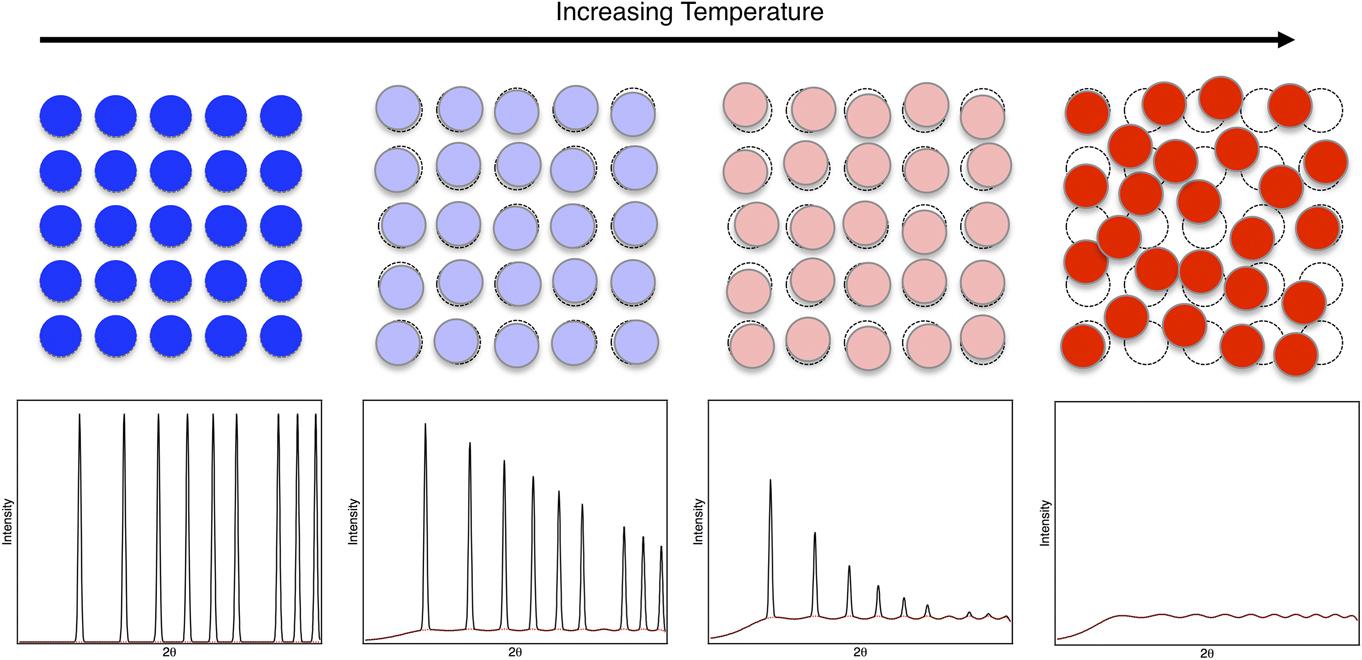
As the temperature of a material increases, so do the magnitudes of the thermal oscillations. This results in an increase in the decay rate of the Bragg peaks, with the pattern becoming featureless at high angles. Mathematically, this results in an increase in the size of the Debye-Waller factor, which is related to the atomic displacement parameter (U) by B = 8π2U.
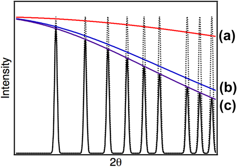
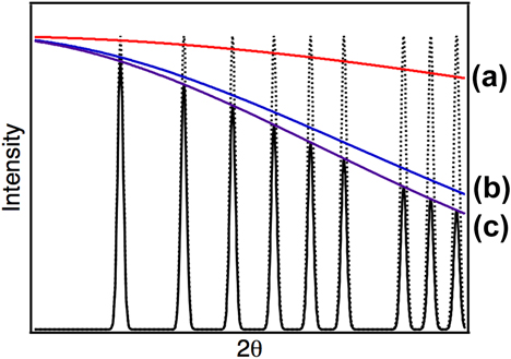
On the time scale of a diffraction experiment, the static displacements and averaged thermal oscillations would have the same observed effect on the position of the atoms, and hence on the Bragg diffraction pattern, Fig. 3. Increases in the level of local lattice strains should therefore result in a similar observation to increased temperature, i.e., a greater decay rate in the Bragg peak intensity at high angles. This can be determined mathematically by recording the Debye–Waller factor from full pattern fitting using the Rietveld method.Reference Rietveld14
Illustration of the effect of static and dynamic displacements on the angular decay of a neutron diffraction pattern. Dotted peaks indicate the expected pattern if all atoms sit on their ideal atomic positions with no thermal or static displacements. Red line (a)—the expected decay caused by static off-site displacements. Blue line (b)—the expected decay resulting from thermal displacements. Purple line (c)—the combined decay curve from the two effects. The solid peaks show the result when both thermal and static displacements are accounted for.
However, when performing such experiments, particularly on laboratory equipment, there can be large sources of error associated with the measurement of Debye–Waller factors using this method. Such fitting is dependent on the accurate measurement of the intensity of the Bragg peaks. This can be highly problematic on a laboratory-based diffractometer, due to the relatively poor instrumental resolution and high background signal of such instruments. Additional considerations also need to be made for any other factors that may affect the intensity of the peaks.
Some of these factors, such as chemical homogeneity or the presence of any preferred crystallographic orientation, can be controlled through careful sample preparation. For example, the studied material should be in a homogenous and annealed state that approximates a crystallographic powder, such that the influence of Types I, II, and III strains are minimal. In particular, it is desirable to ensure that the dislocation density is as low as possible, as atoms around the core of such defects are naturally displaced from their ideal locations. Thus, by annealing, the number of line defects within a material is reduced, which minimizes the local strain caused by the dislocation population and allows the lattice distortions due to solute atoms to be assessed.
Even with careful sample preparation, there are other factors that affect the intensity that are more difficult to control. For example, fluorescence can occur when certain elements are irradiated by particular incident wavelengths, resulting in anomalous levels of incoherent scattering. Similarly, sample-dependent absorption can be difficult to quantify and can lead to large variations in the refined Debye–Waller factors. Therefore, care must be taken when performing such experiments to ensure that these effects are minimized if accurate Debye–Waller factors are to be measured and, by comparison, allow the strain displayed in different materials to be quantified.
Furthermore, as X-rays scatter from the electron cloud of a material, and not a single point source, there is a known angular dependence on the magnitude of scattering from an atom, known as the atomic form factor. This also leads to an angular decay in the intensity of the Bragg peaks. Consequently, the natural decay of the peak intensity, which arises from the atomic form factor, makes the determination of the decay that results from local lattice strain more challenging.
B. Advanced scattering techniques
One way to increase the accuracy of such measurements is to reduce some of the complicating factors listed above. The use of high-energy synchrotron radiation facilitates this by: increasing the signal-to-noise ratio of the data, enabling the incident energy to be tuned to avoid fluorescence and reducing the influence of absorption. This resulting far higher quality data than can be obtained from a laboratory diffractometer. Similarly, the use of neutrons as incident radiation can also be valuable in this respect. Neutrons are more weakly interacting with material, and more penetrative compared with X-rays. Consequently, absorption effects are likely to be comparatively weaker than those observed from X-rays. Additionally, samples used in neutron experiments are much larger and so sampling statistics are increased.
As previously discussed, the effect of the X-ray form factor will also increase the error on the measured magnitude of the local strain effect. However, unlike X-rays, neutrons scatter from the nucleus and, therefore, the system can be considered as a series of point scatterers. Therefore, there is no angular dependence on the observed neutron scattering length. Consequently, there will be no decay of the Bragg intensities at high diffraction angles and, thus, the refined Debye–Waller factors are likely to be more accurate.
Whilst this all seems very advantageous, the obvious downside to such experiments is the requirement for a neutron source—either a spallation source or a nuclear reactor and, as such, prevents any quick ‘in-house’ measurements.
Scatter from materials is typically separated into two components: the diffuse and the Bragg scattering. The Bragg data provide the average crystallographic description of the unit cell, whilst the diffuse scattering provides information of the local environment of a material. If an amorphous material is considered, then, by definition, the lack of any long-range correlations in the system will result in the absence of Bragg peaks. However, diffuse scattering still occurs due to the presence of local interactions within the system. As defined in Sec. II.A, static displacements are a local effect and, as such, would contribute to the diffuse signal.
Early observations by HuangReference Huang15 and BorieReference Borie16 noted that the presence of large atoms within a structure resulted in a change in the modulation of the diffuse scattering intensity. Likewise, it was noted that as the temperature of a system increased, there was an increase in the diffuse scattering of the system, in addition to the reduction in the intensity of the Bragg peaks already discussed, as shown in Fig. 4. Thus, the diffuse scattering provides atomic scale information on the interactions between neighboring atoms relating to both the static and dynamic displacements.
Schematic illustration of the variation in an idealized neutron scattering pattern caused by increased thermal vibrations (dynamic displacements in the system). For each pattern, the total scattering measured is shown in black and the contribution of thermal diffuse scattering shown by the red dotted line.

Initially, analysis of diffuse scattering was restricted to a consideration of diffuse streaks in single crystal diffraction patterns. Such analysis is laborious and requires extensive ab initio modeling of the system to interpret. More recently, however, many studies of these local effects have turned instead to a consideration of powder diffraction data. Total scattering is the simultaneous consideration of both the Bragg and diffuse scatter produced by a sample and can provide greater insight into the local environments of a host of complex materials.Reference Playford, Owen, Levin and Tucker17,Reference Egami and Billinge18
It can be shown that the total scattering function, F(Q), from a sample is given by
 $$F\left( Q \right) = {1 \over N}\sum\limits_{i \ne j} {{{\bar{b}}_i}{{\bar{b}}_j}} {{\sin \left( {Q\left| {{r_i} - {r_j}} \right|} \right)} \over {Q\left| {{r_i} - {r_j}} \right|}}\quad ,$$
where  ${\bar{b}_i}$ and
 ${\bar{b}_j}$ are the scattering lengths of atoms i and j, Q is the magnitude of the scattering vector, N is the total number of atoms, and r i and r j are the instantaneous position of the atoms i and j.
Whilst the diffuse scattering contains the local information required for the assessment of the local lattice strains, it is not immediately accessible without extensive modeling. More useful in the analysis of total scattering is the use of the pair distribution function (PDF). Mathematically, this is given by the Fourier transform of the total scattering function F(Q):
 $$G\left( r \right) = {1 \over {{{\left( {2\pi } \right)}^3}{\rho _0}}}\int_0^\infty {4\pi {Q^2}F\left( Q \right)} {{\sin \left( {Qr} \right)} \over {Qr}}{\rm{d}}Q\quad ,$$
where
 $$G\left( r \right) = \sum\limits_{i,j} {{c_i}{c_j}} {\bar{b}_i}{\bar{b}_j}\left( {{g_{ij}}\left( r \right) - 1} \right)\quad ,$$
ρ0 is the atomic density of the material, and g ij(r) is the partial PDFs, i.e., the distribution of atom type j around atom i.
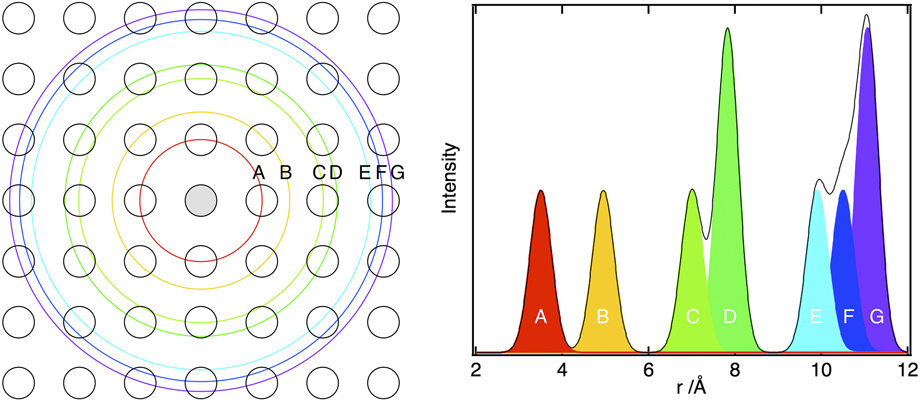
The PDF therefore provides a weighted histogram of the interatomic distances present in a material, Fig. 5. As such, it is often used, owing to the intuitive nature of the information it provides. Peaks in the PDF are indicative of interatomic distances within a material, with the area being dependent on the number and type of coordinating atoms at that distance. The peak shape will be a function of the distribution of atoms at that distance, and so the width of the peak will provide a measure of the displacement of the atoms away from one another, Fig. 6. If total scattering from the sample can be measured and the PDF calculated, it is possible to give an estimate of these values. A more in depth explanation of the use of total scattering for the analysis of local strains can be found in Ref. Reference Owen19.
PDF from a 2D square lattice. Colored peaks in the PDF correspond to the coordination shells shown on the left.
Schematic showing the contribution of static and dynamic displacements to the observed PDF peak width. The diagram on the right shows an example of some real data for several simple binary alloys and more compositionally complex systems. This figure is directly reproduced from Ref. Reference Owen, Pickering, Playford, Stone, Tucker and Jones47 (https://doi.org/10.1016/j.actamat.2016.09.032) under the terms of the Creative Commons Attribution License (CC BY—https://creativecommons.org/licenses/by/4.0/).

One of the main disadvantages with the total scattering method is the necessity to use large-scale facilities. As can be seen from Eq. (4), the calculation of a PDF requires the integral over all Q-space. This will necessarily be physically limited by the diffractometer and incident radiation used in an experiment. Maximizing the Q-range over which the data can be transformed requires short wavelength radiation. Consequently, the use of high energy X-rays, such as those produced at a synchrotron, or spallation neutrons are required to accurately determine a PDF.
Whilst the PDF will provide an easily measurable metric for the local distortions, it is reliant on a correct calculation and normalization of such a function. Therefore, modeling may be required to determine some of the correction and normalization factors used in the calculation of a PDF. It is common to use both small and large box modeling, e.g., PDFGuiReference Farrow, Juhas, Lui, Bryndin, Bozin, Bloch, Proffen and Billinge20 and RMC techniques,Reference McGreevy and Pusztai21,Reference Tucker, Keen, Dove, Goodwin and Hui22 respectively, for the analysis of total scattering functions, and both can provide useful information on the correct normalizations of these functions.
Other probes of the local environment also exist, most notably EXAFS, which can be used to provide information about the local distortions in a structure. EXAFS considers the oscillations that occur after an X-ray absorption edge, and a mathematical analysis of this fine structure can yield local structural information. To access these edges, a tunable high-energy source is required, which necessitates the use of a synchrotron facility. As the fine structure data are absorption edge specific, the technique has the advantage (over the total scattering method) that it is possible to extract element-specific information, i.e., the local environment around an atom A corresponding to an A-edge transition. However, when considering the local lattice strain, this may be a disadvantage, as separate measurements would be required for every individual atom type, potentially making the experiment laborious.
Furthermore, owing to the decay rate of the information, it is often considered that EXAFS is only able to accurately access the first two coordination shells. Depending on the correlation length over which the distortions are expected to take place, this may affect the utility of the technique for measuring the strains. Additionally, the resolution in real space is highly dependent on the energy range over which the measurements can be made and the fine structure determined. If the absorption edges of the material are too closely spaced, then the next absorption edge may cut off the range over which the oscillations can be accurately measured. This may be significant, particularly when considering HEAs, e.g., those in the CrMnFeCoNi family, where the edges of the atoms will be closely spaced due to the similarity of their electronic structures. If such effects are not problematic, however, it may be possible to obtain a measurement of the distribution of bond lengths around a given atomic type from EXAFS. This can be interpreted in a similar manner to the peaks in the PDF, with the width of the distribution being a measure of the local lattice strains in the system.
C. Transmission electron microscopy
The availability of modern, highly stable aberration corrected transmission electron microscopes (TEM) has enabled the development of new methodologies for measuring strain at refined length scales. Several TEM-based approaches may be used, with each approach offering a different combination of precision, length scale, field of view, and processing time, allowing the most suitable methodology for a given application to be selected.
Dark field electron holography is an off-axis two-wave technique that is widely used in the semiconductor industry to measure strains at the nanometer scale in electronic devices.Reference Hÿtch, Gatel, Houdellier and Snoeck23,Reference Hÿtch, Houdellier, Hüe and Snoeck24 The strain data are acquired by analyzing the phase differences present in a hologram created by interfering the two electron beams, one of which passes through a strained region of interest, whilst the other passes through adjacent unstrained reference material. The technique can be applied over large areas and has a high level of precision.Reference Hÿtch, Gatel, Houdellier and Snoeck23 However, measurements of this type are extremely sensitive to variations in sample thickness and, in essence, require perfectly flat specimens.Reference Béché, Rouvière, Barnes and Cooper25 In addition, the need for strain-free reference material close to the area of interest makes it unlikely that this technique is suitable for studying local lattice strain in HEAs.
High-resolution transmission electron microscopy (HRTEM) enables the determination of the positions of the atomic columns within a material, but the accuracy of these positions is reliant upon the aberration correction of the instrument. Assuming that the instrument is stable, then the local strains present within a crystal can be established from such images using a number of different techniques, for example, point pair analysis in real spaceReference Galindo, Kret, Sanchez, Laval, Yáñez, Pizarro, Guerrero, Ben and Molina26 or geometric phase analysis in Fourier space.Reference Hÿtch, Snoeck and Kilaas27,Reference Rouvière and Sarigiannidou28 However, high-resolution images are very sensitive to sample thickness and variations can lead to contrast inversion, which creates artifacts in the resulting strain data. This particular issue can be overcome by acquiring data using the high angle annular dark field imaging mode in a scanning transmission electron microscope (HAADF STEM), which through a combination of the annular detector and atomic number sensitivity enables direct interpretation of the atom column locations.Reference Ozdol, Gammer, Jin, Ercius, Ophus, Ciston and Minor29,Reference Cooper, Denneulin, Bernier, Béché and Rouvière30 Images acquired in this mode are obtained along a zone axis and are essentially insensitive to variations in specimen thickness. However, since the data are acquired in a scanning mode, changes in conditions as the beam rasters across the sample can lead to variations in the relative atom column positions and, therefore, artifacts in the calculated strain maps.Reference Jones and Nellist31 Despite the fact that these artifacts can be accounted for, through post processing, the signal-to-noise ratios of these datasets are much lower than those acquired by other techniques.Reference Cooper, Denneulin, Bernier, Béché and Rouvière30,Reference Braidy, Le Bouar, Lazar and Ricolleau32 Thus, whilst the spatial resolution of high-resolution images is very good, ∼0.03 Å,Reference Hÿtch, Putaux and Pénisson33 the precision of the data is lower and is insufficient to provide detailed quantitative results as to the magnitude of the strains.Reference Cooper, Denneulin, Bernier, Béché and Rouvière30 This is a critical factor when considering approaches for assessing the magnitude of local distortions in HEAs.
Another method of assessing strains at a refined length scale is through nanobeam electron diffraction, where diffraction patterns are acquired on a pointwise basis from a near parallel beam scanned across a sample.Reference Usuda, Numata, Irisawa, Hirashita and Takagi34 Strains can be calculated by the comparison of the diffraction pattern acquired at each point to a reference pattern that can be obtained from anywhere else in the sample. Consequently, this technique can be used over large areas without the need for a nearby reference. One challenge for this approach is the nonuniform intensity of the diffraction spots, which can result in significant inaccuracies in positional determination. This complication also makes the data very sensitive to specimen condition and uniformity. Greater precision can be obtained by utilizing precession techniques that even out the intensity of the diffraction spotsReference Vincent and Midgley35 and enables the use of smaller probe sizes. In general, precession nanobeam data offers the best combination of precision and spatial resolution and, unlike techniques that rely on differences in electron phase, it is largely insensitive to thickness variations. As such, it would seem a logical technique to apply to the field of HEAs; however, as the spatial resolution is currently on the order of ∼1 nm,Reference Rouvière, Béché, Martin, Denneulin and Cooper36 an enhancement in the technique would be required to study lattice strains.
All the above-mentioned techniques are potential methods by which the nanometer length scale strains within a material can be assessed. However, it is critical to recognize that any TEM-based strain measurement needs to be treated with some care, as the thinning of the sample, to allow electron transmission, creates free surfaces that enable some of the material to relax when compared to its condition in the bulk. It has been estimated that the extent of relaxation is around 10% of the original strain level but it can be much greater.Reference Hÿtch, Gatel, Houdellier and Snoeck23 As such, the extraction of quantitative strain data from a thin specimen is further complicated by the need to account for the relaxations. By contrast, the X-ray and neutron diffraction techniques described in Sec. III.B are bulk material techniques and, as such, will not suffer from these effects or require such corrections. It is also worth mentioning that most strain mapping techniques have been developed and validated using pure materials, rather than compositionally complex alloys. In addition, electron phase based methods are particularly sensitive to the presence of defects, such as dislocations, which can further complicate the interpretation of the strain maps obtained.
D. Thermal contributions
With all the experimental methods discussed so far, it is important to note that, on the timescale of the experiment, it will be impossible to distinguish the static component of the distortion from the thermal fluctuations. To accurately determine the magnitude of the local lattice strains, it will be essential to provide some note of the relative magnitude of these two effects. This will be of particular importance when comparisons are made between different material systems.
Practically, experiments designed to compare the relative strain of different materials will be carried out at the same temperature. It could initially be assumed that at a single temperature, the magnitude of the thermal oscillations would be the same. Whilst it is true that at a given temperature the thermal energy of two systems will be the same, the magnitude of these vibrations will be highly dependent on the elastic properties of the system and, hence, will be different for different materials. It is likely, therefore, that the magnitude of the thermal displacements will be related to the melting temperature (T m).Reference Cullity37 A much better approximation is that the magnitude of thermal oscillations in a system is the same for materials at the same homologous temperature (T/T m). Therefore, when comparing materials measured at the same temperature, it may be necessary to consider the homologous temperature of the alloy to provide an indication of the likely magnitude of the off-site displacements corresponding to the thermal component.
Alternatively, it may be possible to provide an estimate for the magnitude of the thermal component by performing variable temperature experiments. As the temperature of a material is reduced, the magnitude of the thermal oscillations will decrease, whilst the strain contribution should remain constant. By measuring, under variable temperature conditions, the U values, the change in PDF peak widths, or the size of an atomic column in an electron microscope image, the absolute magnitude of the strain and relative contributions of the static and dynamic components could be calculated.
When considering the thermal contribution, an additional word of caution is required for data obtained in TEM experiments. It is well understood that the high energy of the electron beam results in a certain amount of heating of the sample, for example, leading to the vaporization of some organic compounds. Ascertaining the precise temperature of a TEM sample is difficult and may lead to some additional errors when separating the static and dynamic components to obtain the local strains in a system.
IV. EVIDENCE OF A HIGHLY DISTORTED STRUCTURE
A. Experimental data relating to local lattice strain
When considering the vast array of HEA-related literature that now exists in the public domain, there are countless references to alloys that have severely distorted lattices but very few of these provide any sort of experimental evidence to support this suggestion. There are also many instances where HEAs are referred to as having highly distorted structures based upon the difference between their lattice parameter and that of a pure element. However, statements based on such comparisons are a misinterpretation of the length scale over which lattice distortions occur. There is no reason why a dilated structure needs to be strained. In fact they are more likely to contain lower levels of local strain since the bulk dilation will be a direct consequence of the material minimizing the internal strain energy. In this section, we provide a critical review of those studies that have made an attempt to establish evidence as to the magnitude of the local lattice distortions, taking into account the information provided in the previous section that discussed how strains of this type could be assessed. As mentioned in Sec. I, the scope of this work will be restricted to attempts made to directly measure or observe the local lattice strain and, therefore, will not consider studies which infer local lattice strain from the variation in the physical properties of the material.
One of the first attempts to provide experimental data to support the concept of the highly distorted lattice in HEAs was made by Yeh et al.Reference Yeh, Chen, Gan, Lin, Chin, Shun, Tsau and Chang38 in 2004. Three different alloys from within the AlCrFeCoNiCu system were studied following arc melting using laboratory-based XRD with a Cu target. The concentrations of both Cu and Al were varied within this study, which, given the relatively large atomic radii of these elements compared to the other constituent species, would have been expected to have a pronounced effect on the local strain in the lattice. It should be noted that the as-cast samples had a dendritic microstructure and significant levels of segregation, particularly with respect to Cu, which makes interpretation of these results much more challenging. Nevertheless, it was stated that the intensities of the diffraction peaks obtained from the HEAs were lower than those of conventional alloys measured under the same conditions. As outlined previously, an increased decay in the intensity of the Bragg peaks at high angles would be expected if the local strains in the lattice were increased. Consequently, this observation was taken as direct evidence of the highly distorted crystal structures present in the multicomponent alloys. However, as previously discussed, there are a number of other factors that could also lead to lower diffracted intensity. Most notably in this case, the chemical inhomogeneity identified in the dendritic microstructure will cause variations in the measured intensities. Furthermore, the large crystallite size observed in the material will mean a small number of illuminated grains and a pronounced texture in the data (as the sample will no longer contain a statistically random orientation of crystals). Most significantly, no comparative data or numerical measure of U relating to a conventional alloy, or even a pure element, was provided. Without such a comparison, it is very difficult to consider if the level of decay observed in the pattern is significant. Even if it had been, great care must be taken when making comparisons of intensities from such samples, as obtaining two identical measurements from a laboratory diffractometer is extremely challenging.
Similar observations have been reported in several other manuscripts, as part of a series of systematic studies considering elemental concentration effects in related base systems, and have been used to indicate a high level of lattice distortion.Reference Wang, Zhang and Chen5,Reference Yeh, Chen, Gan, Lin, Chin, Shun, Tsau and Chang38–Reference Wang, Wang, Wang, Tsai, Lai and Yeh43 Whilst these studies have the advantage of allowing a comparison with systems that would be assumed to be less strained, the same concerns as discussed above also apply to the data presented in these studies. Despite efforts to minimize these effects, some of the data presented in Refs. Reference Yeh39–Reference Yeh, Chang, Hong, Chen and Lin42 clearly indicate that other factors are having a significant influence on the intensities of the reflections within the reported diffraction patterns. For example, if the intensities of the {111} and {200} reflections are compared for the Al0CrFeCoNiCu and Al0.3CrFeCoNiCu alloys reported in Ref. Reference Tong, Chen, Chen, Yeh, Shun, Tsau, Lin and Chang40 (bottom two traces in Fig. 4 in Ref. Reference Tong, Chen, Chen, Yeh, Shun, Tsau, Lin and Chang40), then quite different trends are observed. In the Al0CrFeCoNiCu pattern, the {111} reflection has a far greater intensity than the {200}, whilst in the Al0.3CrFeCoNiCu data, the {200} intensity is significantly greater than that of the {111}. The theoretical intensity ratio between these two reflections, assuming that they exist as randomly orientated solid solution phases, is ∼0.46. If considering the effect of local lattice distortion in isolation, there is no way to explain the reversal in the relative intensities of the first two peaks. Instead, this reduction in intensity of the first peak suggests that relatively few grains contributed to the diffracted signal. Thus, without accounting for this additional textural effect on the observed peak intensities, extreme care must be taken when making any sort of comparison of intensity between different samples.
It is essential to ensure that all potential sources of intensity variation are accounted for when making such comparisons. For example, a series of equiatomic alloys from the CrMnFeCoNi system were presented in Ref. Reference Yeh39, where the compositional complexity of the alloy was systematically increased with each variation, starting with pure Ni and ending with the quinary CrMnFeCoNi alloy. The corresponding diffraction patterns showed a marked decrease in signal with increased alloying, which was again used to support the concept that the lattice distortion increased with compositional complexity. However, the second element added to the Ni base was Fe and a large reduction in intensity was observed from this particular alloy onwards. Consequently, in addition to the textural effects already discussed, the presence of a significant concentration of Fe in the alloy would dramatically reduce the expected diffracted intensity as the wavelength of the Cu Kα incident radiation is just below an absorption edge in Fe, leading to fluorescence.
As part of these studies, a simple model was developed to describe the enhanced Bragg damping that would occur as a result of the lattice distortions.Reference Yeh, Chang, Hong, Chen and Lin42 It was proposed that the influence of these distortions would take the same form as the Debye–Waller factor but with the amplitude term, u D, being related to the off-site displacements rather than thermal oscillations, u T.Footnote c It was also proposed that the magnitude of u D would be equal to the root mean square of the difference between the elemental lattice parameter and that of the alloy itself.Reference Yeh, Chang, Hong, Chen and Lin42 This approach will be discussed further in Sec. IV.B.
Unfortunately, due to the various experimental issues outlined in the preceding paragraphs, these studies are unable to unambiguously demonstrate the decay in the Bragg data that would be expected from an increase in local lattice strain. Furthermore, even if ideal powder samples were studied using laboratory equipment, it is unlikely that the data would have sufficient resolution or be sufficiently reproducible to facilitate any kind of quantitative analysis as to the magnitude of the static displacements. Consequently, to try to overcome some of the issues associated with laboratory diffraction, several studies have utilized advanced characterization techniques to specifically probe the local lattice displacements and separate the static component from the dynamic, thermal term. These include the use of high-resolution TEM,Reference Zou, Maiti, Steurer and Spolenak44 as well as advanced diffraction and scattering techniques that are available at National Synchrotron and Neutron Facilities.Reference Okamoto, Yuge, Tanaka, Inui and George45–Reference Santodonato, Zhang, Feygenson, Parish, Gao, Weber, Neuefeind, Tang and Liaw49
HRTEM has been used to study the lattice of the refractory metal HEA NbMoTaW in an annealed state.Reference Zou, Maiti, Steurer and Spolenak44 The lattice fringes in a Fourier filtered high-resolution image were reported to contain bends, which were purported to be a result of local distortions. However, these features are not necessarily an exclusive result of the lattice strain. The raw high-resolution image clearly indicated that the imaged region contained variations in the thickness of the foil, which could also give rise to similar effects in the Fourier image. Nevertheless, if these are assumed to be local distortions then the static component can be calculated from the reported atomic displacement parameter of 0.0091 Å2 by removing a calculated dynamic, thermal contribution of 0.0037 Å2. Thus, the remaining 0.0054 Å2 corresponds to a static displacement of 0.074 Å, which was in good agreement with a theoretical value, predicted using an approach similar to that outlined in Ref. Reference Yeh, Chang, Hong, Chen and Lin42.
An alternative attempt to separate the static and dynamic displacement terms has been made using synchrotron radiation in conjunction with a cryogenic sample environment.Reference Okamoto, Yuge, Tanaka, Inui and George45 Diffraction data from a single crystal sample of CrMnFeCoNi, machined from a larger homogenized and recrystallized bar, were obtained at temperatures of 300 and 25 K. Since the magnitude of thermal displacements decreased as a function of temperature, it was assumed that they would be near zero in the measurement made at 25 K. Consequently, the extent of the measured atomic displacement parameter, 23.5 pm2 at 25 K, was believed to represent the extent of the static displacements. The magnitude of this value correlated well with the results of complimentary ab initio modeling, which, therefore, supported the suggestion that the thermal contributions at this temperature were minimal. As such, it was concluded that the lattice strain in the HEA was significant, as the static displacements in a pure metal would be zero. Whilst this statement is true, the comparison with a pure element is not necessarily that useful, as any alloy would have some level of static displacement. As such, to put this measurement of the static displacement present within the HEA into context, the magnitude of the local lattice strain really needs to be compared to similar data acquired from conventional alloys that are not thought to have severely distorted lattices.
Another notable study in this area investigated the displacements of individual elements within the CrMnFeCoNi alloy using advanced X-ray adsorption measurements.Reference Oh, Ma, Leyson, Grabowski, Park, Körmann and Raabe46 EXAFS measurements were acquired from a homogenized sample of CrMnFeCoNi under ambient conditions and the results compared with ab initio models. The modeled mean distortions of the bond lengths for each atomic species agreed well with the corresponding values obtained experimentally from the absorption measurements, indicating that the model was describing the system well. Critically, the calculations also revealed that, despite the mean bond lengths being similar for all bond types, the widths of the distributions for each bond type were markedly different. The variation in the widths of these distributions were an order of magnitude greater than the variation in the average values and were found to be particularly pronounced for the bonds surrounding Cr and Mn. The prediction of these variations led to the suggestion that significant local distortions may well be present in the lattice of CrMnFeCoNi and highlighted the need to experimentally assess the static displacements using a technique capable of characterizing the distribution in the length of a given bond.
As mentioned in Sec. III.B, one characterization technique that is capable of providing information about the distribution of bond lengths, and potentially even separate the different bond types, within a material is total scattering. Consequently, with suitable samples, this method is probably the most appropriate approach for assessing the concept and magnitude of lattice strain.
X-ray and neutron total scattering has been used to study the local distortions in a ZrNbHf ternary alloyReference Guo, Dmowski, Noh, Rack, Liaw and Egami48 and an Al1.3CoCrCuFeNi HEA.Reference Santodonato, Zhang, Feygenson, Parish, Gao, Weber, Neuefeind, Tang and Liaw49 In both cases, there were variations in the PDF peaks that corresponded to the first few coordination shells, which were taken to indicate the presence of local lattice distortions. However, the samples in both of these studies were considered in the as-cast state, which raises similar homogeneity concerns to those outlined above for laboratory diffraction experiments. It is likely that the form of a PDF peak would be influenced by the microsegregation that is present in all cast materials, and this additional complexity in the dataset may make extraction of information relating to local distortions extremely difficult. The complexity of the analysis also increases dramatically when the sample contains more than one phase, as the PDF will now contain coordination data for each bond type in every phase. In addition, there was evidence that the samples also exhibited preferential crystallographic alignments, which will affect the scattering behavior of the materials. At present, there is no established or verified relationship that describes how the local information obtained from the diffuse scattering is influenced by the crystallographic texture. Thus, these data may contain artifacts that cannot currently be accounted for and, as such, it is difficult to reasonably extract information corresponding to the static displacements.Reference Owen, Playford, Stone and Tucker50
Neutron total scattering has also been used to explore the local lattice distortions in CrMnFeCoNi, four compositionally simpler alloys from within the same system, and pure Ni.Reference Owen, Pickering, Playford, Stone, Tucker and Jones47 Critically, and in contrast to the other studies discussed so far, the samples in this study were characterized in powder form, eliminating many of the scattering complications previously outlined. All the alloys were shown to be single-phase materials with an fcc crystal structure and were well described as a random solid solution in both long-range and short-range datasets. The diffraction peaks from all the alloys remained sharp, even at high angles, thus the pronounced Bragg intensity damping that would be expected from a material with a highly distorted lattice was not evident. This observation was further reinforced by a quantitative assessment of the widths of the peaks in the associated PDF, which correspond to the variation in the bond lengths for each coordination shell. The widths of the first 6 coordination shells were assessed by fitting normal distributions to the PDF peaks for all the materials considered. In the first five shells, the distribution of the bond lengths was greatest for the equiatomic HEA, CrMnFeCoNi. Whilst this observation might initially be taken as providing strong evidence for a highly distorted lattice, an objective assessment requires these widths to be compared to those of the other, compositionally simpler alloys and care also needs be exercised as these measurements were made at room temperature and, therefore, the PDF peak widths also contain a thermal component. In all the coordination shells considered, the magnitude of the PDF peak widths for the CrMnFeCoNi HEA were similar to those of Ni–33Cr (at.%) and Ni–37.5Cr–25Co (at.%). In addition, whilst the dynamic term could not be unambiguously separated from the static term in this dataset, the melting temperature of the HEA was considerably lower than that of the other alloys, meaning that the magnitude of the thermal component would be expected to be greater. Consequently, it was concluded that whilst the HEA did exhibit local lattice strain, so did the other alloys and the magnitude of these displacements were not dramatically different. As such, it was concluded that there was no clear evidence within this dataset to indicate that the lattice of CrMnFeCoNi was severely distorted.
B. Prediction of lattice strain
As mentioned in Sec. IV.A, one simple approach to estimate the local lattice strain has been proposed using the lattice parameters of a material, as outlined in Ref. Reference Yeh, Chang, Hong, Chen and Lin42. A modification to this approach was made in Ref. Reference Zou, Maiti, Steurer and Spolenak44, where the lattice parameters of each elemental species were compared to the experimentally measured lattice parameter of the HEA rather than the average of the individual elements. However, in both cases, it is unclear what the physical basis was for formulating this expression using lattice parameters, especially since multicomponent alloys may well require the cross interpretation of elemental species with different crystal structures. An alternative method of utilizing this approach, and one that avoids the problem of structural variations between alloys and constituent elements would be to replace the lattice parameters with atomic radii. These can be determined by applying a hard sphere model to experimental data of the individual elemental species and the HEA itself. For example, using the Goldschmidt radii of the constituent elements and the lattice parameter of CrMnFeCoNi reported in Ref. Reference Okamoto, Yuge, Tanaka, Inui and George45, the local lattice strain is predicted to be 0.048 Å, which is in very good agreement with the corresponding experimental value.
However, such simple approaches need to be treated with caution, as, when elements combine to form a solid solution, it is far from clear how the electron orbitals of the different species interact. Therefore, it is also unknown what the appropriate radius of each element in a given solid solution might actually be. This point is often considered as one reason why Vegard’s law breaks down when attempting to predict the lattice parameter of ternary or higher order alloys. This has led to the concept of an effective atomic size of an element in a given alloy, which has led to some studies attempting to quantify these effective radii.Reference Okamoto, Yuge, Tanaka, Inui and George45,Reference Okamoto, Fujimoto, Kambara, Kawamura, Chen, Matsunoshita, Tanaka, Inui and George51 Consequently, the magnitude of these predicted displacements can vary quite dramatically depending on the particular values for atomic radii selected.
To emphasize this point, if the expected lattice strain in CrMnFeCoNi is predicted using the metallic radii from Ref. Reference Otto, Yang, Bei and George52, then the resulting displacements have a lower magnitude, 0.028 Å, than that predicted using the Goldschmidt radii, 0.048 Å. By contrast, if the effective elemental radii reported in Ref. Reference Okamoto, Fujimoto, Kambara, Kawamura, Chen, Matsunoshita, Tanaka, Inui and George51 are used, then the magnitude of the of the predicted strain increases to 0.076 Å. These limitations have repercussions for all atomic size-based approaches that do not allow any form of relaxation in the structure (e.g., Refs. Reference Toda-Caraballo and Rivera-Díaz-del-Castillo53 and Reference Zhang, Zhou, Lin, Chen and Liaw54) and, thus, whilst the predictions of these models may be useful in identifying trends, caution should be exercised when considering their absolute values.
An alternative approach for predicting the off-site atomic displacements in HEAs that shows great promise is through the use of ab initio methods, where the positions of each atom with the modeled cell can be assessed following a full relaxation of the structure. Recently, several studies have utilized this methodology to predict the local lattice strain in a number of HEAs and simpler constituent alloys.Reference Oh, Ma, Leyson, Grabowski, Park, Körmann and Raabe46,Reference Song, Tian, Hu, Vitos, Wang, Shen and Chen55,Reference Ye, Zhang, He, Zhuang, Wang, Shi, Hu, Fan and Yang56 This technique enables the influence of different atomic species on the local distortions to be theoretically explored through the comparison of results from calculations performed in an identical manner. It should be noted that, as with all ab initio calculations, the fidelity of the simulation may be limited by the size of the cell, which, in this case, is unlikely to be large enough to capture all the local environments inherent in such compositionally complex materials. As such, it is critically important to validate the results of these calculations against experimentally determined values.
C. Extent of the directly observed lattice strains
From the studies highlighted in Sec. IV.A, it is clear that data relating to several different HEAs exist. However, many of these datasets contain measurement features that would make the assessment of the local lattice distortions present in the material extremely challenging. In addition, even in those studies where quantitative assessments of the static displacements have been made, the results do not appear to reach the same conclusions. For example, Refs. Reference Okamoto, Yuge, Tanaka, Inui and George45–Reference Owen, Pickering, Playford, Stone, Tucker and Jones47 all present data on annealed samples of CrMnFeCoNi but reach distinctly different conclusions about the level of distortion present in the lattice. However, these statements need to be treated with care, as they depend entirely upon the reference point chosen as the comparator. A more rigorous way to compare the results of these studies would be to establish the magnitude of the static displacement that can be obtained from each measurement. It is not necessarily obvious how this can be done since the results of each study reported the magnitude of the local lattice strain in different forms but, as will be seen in the following paragraphs, with the use of a couple of simplifying assumptions, numerical values relating to the static displacements within the material can be obtained.
Care should be taken to distinguish between measurements that report values of atomic displacements and those that have assessed the variation in bond length. These two measures are related but not equal. An atomic displacement parameter (U) is the variation in atomic position relative to a point, i.e., the ideal atomic site. By contrast, the bond length (r b) is the distance between two atoms, which has a variation of (σrb)2. As atomic displacements are commonly assumed to be normally distributed then these two terms are related by (σrb)2 = 2U. From a practical standpoint, Rietveld refined diffraction data will provide atomic displacement parameters, whilst EXAFS and total scattering data will tend to produce results that correspond to variations in bond lengths.
It should also be noted that as the static and dynamic components are both independent variables with normal distributions, their combined effect can be evaluated through the square of their standard deviations (σ), such that σtotal2 = σdynamic2 + σstatic2.Reference Okamoto, Yuge, Tanaka, Inui and George45
Analysis of the diffraction data collected at 25 K in Ref. Reference Okamoto, Yuge, Tanaka, Inui and George45 produced an atomic displacement factor of 23.5 pm2, which, due to the low temperature of the measurement, was assumed to be entirely related to the static displacements in the crystal. Thus, the standard deviation associated with these static displacements was 0.048 Å.
If the distribution of the bond lengths within the first coordination shell of the PDF data provided in Ref. Reference Owen, Pickering, Playford, Stone, Tucker and Jones47 is considered, then since the full width at half maximum of a normal distribution is 2σ(2 ln 2)0.5, then the value of σrb for CrMnFeCoNi is equal to 0.085 Å. Since this measurement was made at room temperature, this term is σtotal and contains both the static and dynamic components. If it is assumed that the corresponding data from the pure Ni sample contains no static displacements, then the standard deviation of this measurement provides an estimate as to the magnitude of the thermal component. Consequently, an estimate of the variation in the bond length present within the HEA can be made as 0.031 Å, which corresponds to a static displacement of 0.022 Å. It should be pointed out that this value represents an upper bound estimate, as the melting temperature of CrMnFeCoNi has been found to be ∼200 K lower than that of pure Ni and thus the magnitude of its thermal vibrations would be expected to be greater.Reference Owen, Pickering, Playford, Stone, Tucker and Jones47
The ab initio modeling performed in Ref. Reference Oh, Ma, Leyson, Grabowski, Park, Körmann and Raabe46 indicated that within CrMnFeCoNi, there were variations in the bond lengths up to a maximum of ∼3%. If the effect of these variations are considered on the bonds within the first coordination shell, which has a bond length of ∼2.55 Å assuming a lattice parameter of 3.6 Å,Reference Owen, Pickering, Playford, Stone, Tucker and Jones47,Reference Christofidou, Pickering, Orsatti, Mignanelli, Slater, Stone and Jones57,Reference Pickering, Muñoz-Moreno, Stone and Jones58 then the corresponding maximum variation in bond length would be ∼0.08 Å. However, the data in Refs. Reference Okamoto, Yuge, Tanaka, Inui and George45 and Reference Owen, Pickering, Playford, Stone, Tucker and Jones47 correspond to average values acquired from the entire sample and, therefore, it would be more appropriate to compare these to an average variation in the bond length. If a single average bond variation is established from all the different calculated bond lengths in Ref. Reference Oh, Ma, Leyson, Grabowski, Park, Körmann and Raabe46, which has a magnitude of ∼1.8%, then the average variation in bond length is 0.046 Å, which corresponds to a static displacement of 0.033 Å. For reference, all these values can be found in Table I. These static displacements can also be compared to the theoretical prediction outlined in Sec. IV.B, which was 0.048 Å.
Collated values of local lattice strain for multicomponent alloy systems giving original measurement value and standardized variation in bond length.

What is interesting about these extracted static components, obtained from each of the three independent measurements and the simple prediction, is the similarity between their magnitudes. However, it should also be noted that recent ab initio calculations produced results where the static displacement was slightly larger, ∼0.066 Å.Reference Song, Tian, Hu, Vitos, Wang, Shen and Chen55 The variation in these values leads to possibly the most critical question associated with the concept of a severely distorted lattice and one that has yet to be addressed within the HEA literature: What constitutes a significant level of local strain, such that a lattice can be considered to be severely distorted?
D. What is significant lattice strain?
In addressing the question of what constitutes a highly strained lattice, it is pertinent to consider the levels of distortion that exist in more conventional alloys, whose structures are not normally considered to be significantly distorted. As such, the data relating to the distributions of bonds within the first six coordination shells for different materials provided in Ref. Reference Owen, Pickering, Playford, Stone, Tucker and Jones47 will be considered. As mentioned above, within this dataset, the widths of the bond distributions in a Ni–33Cr (at.%) binary alloy and a Ni–37.5Co–25Cr (at.%) ternary alloy were found to be similar to that of CrMnFeCoNi. In fact, if a similar analysis as performed earlier is applied to the data from the first coordination shell, then almost identical values of σstatic are obtained. In this case, Ni–Co–Cr has a similar melting temperature as pure Ni, so this estimate should be reasonable, but Ni–33Cr (at.%) has a melting temperature ∼160 K above pure Ni, so the σstatic value obtained is a lower bound estimate. Consequently, unless the structures of these binary and ternary alloys are also considered significantly strained, then the lattice of CrMnFeCoNi cannot be considered as highly distorted.
The fact that the lattice of CrMnFeCoNi is not highly distorted does not mean that large static displacements cannot exist in other HEAs, particularly those with greater differences in atomic size. However, at present, there is sparingly little data that can be used to test the hypothesis further. A summary of the known direct measurements is provided in Table I, where, following the discussion in Sec. IV.C, the data from each study has also been converted into a consistent format for ease of comparison. It is suggested that studies in this area should, in addition to the measured values, report a static displacement and the ratio of this static displacement to the experimentally measured average atomic radius, determined from the lattice parameter assuming a hard sphere model. The inclusion of these values is essential to provide meaningful comparison between different datasets and different HEA compositions.
Considering the data within Table I, it can be noted that the local lattice strain in the refractory metal-based HEA is greater than that of the CrMnFeCoNi HEA, which seems logical given that the variation in the atomic radii of the refractory elements is much greater than in CrMnFeCoNi. However, whether the magnitude of these displacements is sufficient to be considered significantly strained remains unclear.
One potential way to define a significant lattice strain is to consider how variations in atomic size influence the stability of the solid solution phase. When considering the HEA literature, a commonly used parameter that describes the difference in atomic radii within a given alloy is the δ parameter,Reference Zhang, Zhou, Lin, Chen and Liaw54 which has been used extensively in efforts to define empirical relationships for the behavior of HEAs.Reference Pickering and Jones3,Reference Miracle and Senkov4,Reference Zhang, Zhou, Lin, Chen and Liaw54,Reference Yang and Zhang59,Reference Guo, Hu, Ng and Liu60 One common feature of all these studies is an apparent limit of solid solution stability that occurs when the δ parameter reaches ∼6.6%. This value correlates well with the observed influence of atomic size on the stability of binary solid solutions proposed by Hume-Rothery et al.Reference Hume-Rothery, Mabbott and Channel Evans9,Reference Hume-Rothery, Smallman and Haworth10 Consequently, it has been suggested that for a crystal to be considered severely distorted, the local lattice strain should surpass this value.Reference Owen, Pickering, Playford, Stone, Tucker and Jones47 However, this is merely one suggestion and quantification of the term “significantly strained” remains an open question for the HEA community.
V. CONCLUSIONS AND OUTLOOK
This review has focused on one of the founding core concepts of the HEA field, namely that multicomponent solid solution phases in HEAs have severely distorted lattice structures. By considering the key points relating to its theoretical basis, the methods by which such local distortions might be experimentally measured, and by reviewing those studies that enable direct assessment of the magnitude of the static displacements, the following general conclusions can be drawn.
At present, there is no convincing direct evidence within the literature that supports the hypothesis that the crystal structures of multicomponent HEAs are severely distorted. Modeling and experimental results seem to converge on relatively small displacements, which are of a similar magnitude to those observed in conventional binary and ternary alloys and so it does not seem reasonable to call such distortions severe in HEAs.
However, it should also be recognized that very few alloys have been studied with suitable techniques to make even a reasonable estimate of the static displacements present in their structures and so this conclusion can, in no way, be considered universal. Many more, carefully conceived and conducted, dedicated studies are required, across a much broader range of alloy compositions, before a more overarching statement about this concept can be made.
One critical point that needs to be resolved by the HEA community is exactly what is meant by the term highly strained, especially given the thermodynamic tendency of highly strained phases to decompose. Without a formal definition, the assessment of the static displacements of the atomic species away from their ideal lattice locations for any alloy remains subjective.
Another key point is the importance of ensuring that all measurements of local lattice strain are reported in the same manner. Since lattice strains are local off-site distortions, it is suggested that all studies should report the magnitude of the static displacements in addition to the measured variation in the bond length or atomic displacement parameter. Standardization will facilitate simple cross correlation between different HEAs and the necessary comparisons to compositionally simpler systems.
It is hoped that with further direct experimental measurements of the static displacements within a range of different alloy systems, the extent to which the lattices of HEAs are distorted may be contextually assessed and, thus, the validity of the highly distorted lattice hypothesis fully established.
ACKNOWLEDGMENTS
The authors would like to thank K.A. Christofidou and D. Johnstone for useful discussions and acknowledge the EPSRC/Rolls-Royce Strategic Partnership for support under EP/M005607/1.