I. INTRODUCTION
Cemented carbide is a kind of hard ceramic-based composite, which commonly consists of transition metal refractory carbide and group VIII metal such as cobalt, nickel, and iron. Typical WC-Co cemented carbides are used in the field of cutting tools and abrasion resistant parts, and they are referred to as K typed cemented carbide. To improve further the hardness, wear resistance, and inoxidizability, TiC is introduced to develop WC-TiC-Co cemented carbide, referred to as P typed cemented carbide. Nonetheless, cubic TiC addition is adverse to the material toughness. Thereby Ti is usually introduced in the form of (Ti,W)C instead of TiC to shrink the physical property difference to impede toughness decline. Additionally, TiN or Ti(C,N) is doped to produce the composite containing nitrogen, called “cemented carbonitride”.
The gradient cemented carbonitride is a kind of functionally gradient composites formed by element diffusion. It is depleted in brittle cubic phase but enriched to tough binder in the surface layer. In the inner, the hard cubic phases are remained to provide hardness. The gradient cemented carbonitride is a combination of K typed cemented carbide in the outer and P typed cemented carbide in the inner. When the gradient cemented carbonitride serves as the coated substrate, the tough outer can resist against the crack propagation from the coating to the inner.
Mechanical properties of the gradient cemented carbonitrides are related to the gradient layer thickness, which is influenced by many factors. By summarizing the previous reports, the gradient layer thickness decreased with (i) increasing WC and Ti(C,N) powder particle size when different WC and Ti(C,N) sizes were adopted, Reference Zhou, Wang, Xu, Liu, Li, Wang and He1 (ii) decreasing the sintering pressure when one-step HIP technology was conducted, Reference Zhou, Xu, Wang, Li, Liu, Wang and He2 (iii) increasing TaC or NbC contents when TaC or NbC were added, Reference Zhang, Du and Peng3 (iv) decreasing carbon contents when preparing Ti(C,N)-(Ti,W)C-WC-Co or Ti(C,N)-TaC-WC-Co materials, Reference Frykholm, Jansson and Andrén4 (v) decreasing Ni/(Ni + Co) ratio when partial cobalt was replaced by nickel, Reference Mohammadpour, Abachi and Pourazarang5 (vi) decreasing Fe contents in the binder when adding Fe to Co and Ni binders, Reference Garcia6 (vii) (Ta,Nb)C addition in WC-Co-Ti(C,N)-VC-Cr3C2 materials, Reference Zhou, Xu, Wang, Li, Liu, Wang and He2 (viii) the increase of Ti(C,N) content when ultra-fine TiC0.5N0.5 was added, Reference Xiong, Guo, Yang, Xiong, Chen, Wu, Wen and Cao7 (ix) the increase of Ti content or decreasing N content. Reference Zhang, Du, Peng, Xie, Wen and Wang8
The nitrogen/nitride/carbonitride contents do not have an influence on the gradient layer thickness, but also change the microstructure and properties of the gradient cemented carbonitrides. Gradient structure formation is attributed to the gradient of nitrogen activity during sintering, but is independent on nitrogen introduced methods. Reference Yang, Xiong, Sun, Guo and Ding9 Different nitrogen suppliers gave the alloys distinguishing microstructure and mechanical properties. Reference Yang, Xiong, Sun, Guo and Ding9 Frykholm et al. Reference Frykholm, Ekroth and Jansson10 studied the gradient materials of WC-3.5 wt% Ti(C,N)-6.9 wt% Co with Ti(C,N) as a cubic carbonitride. The clustering of cubic grains was observed in the bulk. Many undissolved Ti(C,N) cores were found near the surface zone as well as in the bulk, but the concentration was higher in the bulk. Binder depletion and cubic phase enrichment were observed inside the zone border. Xiong et al. Reference Xiong, Guo, Yang, Xiong, Chen, Wu, Wen and Cao7 did the research on the gradient cemented carbonitride with ultra-fine TiC0.5N0.5. The results showed that gradient cemented carbides prepared with 0.13 μm ultra-fine TiC0.5N0.5 had lower porosity and higher hardness and transverse rupture strength compared with 1.2 μm TiCN or 3 μm TiN. In the report, 3.9 wt% TiC0.5N0.5 was the optimal addition level in view of hardness and transverse rupture strength. Zhang et al. Reference Zhang, Du, Chen, Peng, Zhou, Wang, Wen and Xie11 believed that gradient cemented carbonitride with low N content has higher fraction of cubic phase and lower fraction of WC phase than that with high N content. However, the samples with high nitrogen content had much smaller grain size than that with low nitrogen content. Reference Zhang, Du, Peng, Xie, Wen and Wang8
In the paper, gradient cemented carbonitrides with different nitrogen contents were prepared. A fundamental investigation on the effects of nitrogen on the microstructural features, composition distribution, transverse rupture strength stability, and fracture morphology were performed at fixed titanium and carbon contents.
II. EXPERIMENTAL PROCEDURES
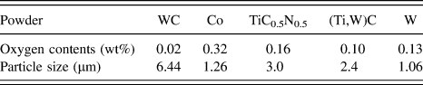
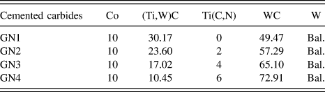
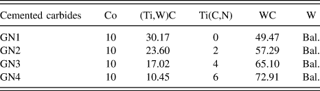
Commercially available WC, (Ti,W)C, TiC0.5N0.5, Co, and W powders were used as raw materials, and their oxygen contents and particle size were listed in Table I, where (Ti,W)C was the solid solution of WC and TiC (70:30, wt%). The specimens named GN1, GN2, GN3, and GN4 were designed according to the compositions of 7.24 wt% Ti-6.13 wt% C-x wt% N-10 wt% Co-W (x = 0, 0.23, 0.46, 0.69, respectively), and they were prepared according to Table II following the powder metallurgical techniques. Firstly, the mixed raw powders were ball-milled for 25 h in stainless steel lined mill with a ball-to-powder weight ratio of 10:1 and a milling speed of 56 revolutions per minutes (rpm). After milling, the mixture was dried for 2 h, and 1.1 wt% synthetic rubbers were added into the mixture as lubricants. Secondly, specimens with the dimension of 6.5 × 5.25 × 20 mm were made in a press die, and the pressed green bodies were sintered in a vacuum furnace at 1440 °C for 1 h. Thirdly, one surface of the sintered specimens were ground using diamond grinding disks with the diamond grit size of 107, 76, 30 to 15 μm to remove the oxide layer and then polished with 1 μm diamond suspension for microstructural characterization.
Oxygen contents and particle size of the raw materials.

Powder mixtures of the cemented carbides (wt%).
S-3400N scanning electron microscope (SEM; Hitachi Corp., Tokyo, Japan) was used for microstructure observation. To inspect gradient layer microstructure, the specimens were cut perpendicularly to the original surface so as to make a cross section visible. To prevent the effects from two-dimensional diffusion, the cutting was performed as far as possible from the corners. For obtaining information on elemental distributions in the near surface zone, EPMA was performed. An EPMA-1720 combined WDS/EDS microanalyzer (Shimadzu Corp., Kyoto, Japan) operated at 15 kV was used. The average composition at different distances from the surface was obtained by performing line sweeps parallel to the surface. After each sweep, the beam was moved 1 μm perpendicular to the surface. In this way the sample was scanned down to 50 μm from the original surface. Different phases showed distinguishing color contrast under the back scattered electron (BSE) mode. Thus the area fractions of binder phase and WC phase could be calculated based on the different color contrasts using ImageJ software. The binder phase fractions in the gradient layer were the average results. The average WC phase fraction at different distances from the surface was obtained by analyzing the strip zones at different distances parallel to the surface. After each measurement, the testing zone was moved 1 μm perpendicular to the surface. The cross section was analyzed totally to 30 μm from the original surface. The lattice parameter of (Ti,W)C was obtained with X'Pert Pro MPD type x-ray diffraction (XRD; PANalytical, Almelo, The Netherlands) and Jade software. EDS analysis on Ti and W contents in (Ti,W)C phase were performed in the bulk inside the gradient border. For GN1, GN2, GN3, and GN4, the testing (Ti,W)C grains were located approximately in the zone of 6–9 μm, 10–13 μm, 15–18 μm, and 22–25 μm from the surface, respectively. Transverse rupture strength (TRS) tests were carried out using a Lloyd EZ50 materials testing machine (Lloyd Instruments, West Sussex, United Kingdom) with a XLC series load cells to measure and record the forces applied. The bending strength can be calculated by:
 $$\sigma = {{3FL} \over {2b{d^2}}}\quad ,$$
where σ is the transverse rupture strength; F is the load at the fracture point (N); L is the distance between the centers of the two support pins (mm); b and d are the width and the thickness of the samples (mm). In this paper, the value of L was set to be 14.5 ± 0.5 mm, and the loading speed was 0.5 mm/min. After each test, the central position and the span of support pins were corrected. A group of 20 samples of each composition were tested to obtain sufficient statistics for subsequent Weibull analysis.
III. RESULTS AND DISCUSSION
A. Effects of nitrogen on the microstructure of gradient layer
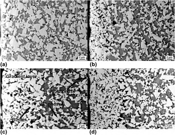
The cross sections of the specimens are illustrated in Fig. 1. Gradient layers were formed in the materials with nitrogen while not seen in the one without nitrogen. As shown in Fig. 1(c), the gradient layer is at the left, and the bulk is at the right. This microstructure was observed using the back-scattered election microscope (BSE), which is sensitive to atomic number. Heavier elements have higher intensity of back-scattered electrons, and give brighter contrast. WC phase appears as bright, (Ti,W)C cubic phase appears as gray and binder phase rich in Co appears as dark. There is no gray (Ti,W)C cubic phase in the gradient layer. Gradient layer formation is correlated with the nitrogen decomposition at elevated temperature. In this paper, Ti(C0.5N0.5) decomposed in the presence of carbon source such as WC, which could be expressed as follows:
 $$4{\rm{Ti}}\left( {{{\rm{C}}_{0.5}}{{\rm{N}}_{0.5}}} \right) + 2{\rm{C}} \to 4{\rm{TiC}} + {{\rm{N}}_2}\quad .$$
SEM images of the near surface zone of the common cemented carbonitride (a) CN1 and the gradient layers of gradient cemented carbonitrides (b) CN2; (c) CN3; (d) CN4.

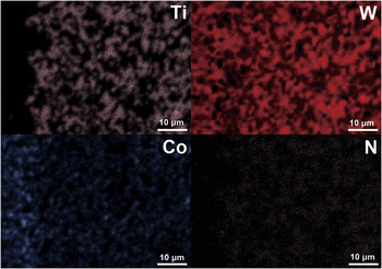
The nitrogen activity descended in the surface layer due to N2 release. There was a strong thermodynamic coupling between nitrogen and titanium, which drove the titanium to diffuse inward to the bulk with a higher nitrogen activity. Reference Ekroth, Frykholm, Lindholm, Andrén and Ågren12 Due to removal of nitrogen and titanium, the liquid cobalt pressure in the surface layer is lowered. The cobalt in the bulk diffused toward the surface layer under the pressure difference. In this way, the surface layers were depleted of titanium and nitrogen but enriched in cobalt. The EDS elemental analysis across the gradient border of GN3 was shown in Fig. 2. Tungsten was distributed uniformly. Titanium appeared only in the bulk, and similarly nitrogen also existed only in the bulk. Cobalt was more in the gradient layer than in the bulk.
Ti, W, Co, and N distributions across the gradient layer.

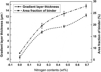
As shown in Fig. 3, the gradient-layer thickness (GLT) increased with more nitrogen added. From what has been discussed above, the gradient layer formation was controlled by element diffusions. The thermodynamic coupling between nitrogen and titanium stemmed from the thermodynamic interaction between nitrogen and titanium. According to Fick–Onsager diffusion equation, the concentration gradient of one species such as nitrogen can provoke diffusion of another species such as titanium. The nitrogen concentration gradient between the surroundings and the gradient cemented carbonitrides augmented when the nitrogen content was increased, and this hence promoted larger diffusion flux of titanium. Titanium diffusion dominated the formation of the gradient layer. Reference Schwarzkopf, Exner and Fischmeister13 A thicker gradient layer was developed due to larger diffusion flux of titanium. Besides, the area fraction of binder phase in the gradient layer increased with the gradient layer thicker, indicating more cobalt diffusion to the gradient layer.
Gradient layer thickness and area fraction of binder with the nitrogen content.

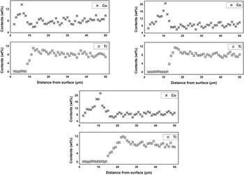
The distributions of Ti and Co were demonstrated in Fig. 4. Titanium was depleted in the gradient layer. At the gradient border, it rose significantly, and reached the maximum in the bulk inside the gradient border. Then it diminished to the bulk level. The maximum of titanium content in the bulk was enlarged slightly with the nitrogen increased. Cobalt contents increased gradually close to the gradient border. The maximum of cobalt content was obtained in the gradient layer near the gradient border. However, the cobalt returned to the bulk level inside the gradient border. The maximum cobalt contents in the gradient layers of GN2 (0.23 wt% N), GN3 (0.46 wt% N), and GN4 (0.69 wt% N) were approximately 1.36, 2.07, and 2.14 times as many as the nominal contents in the raw materials, respectively. It is indicated that the difference between the maximum and the nominal cobalt content augmented when more nitrogen was added.
Co and Ti distribution across the gradient layers.

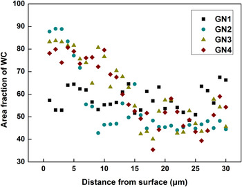
Figure 5 revealed the area fraction of WC phase at different distances from the surface. WC distributed in fluctuation in the homogeneous cemented carbide (GN1). However, the area fraction of WC was much higher in the gradient layer than in the bulk for the gradient cemented carbonitrides. Close to the gradient border, it decreased remarkably owing to cobalt enrichment. The maximum area fraction of WC phase descended when more nitrogen was added.
WC phase distribution across the gradient layers.

WC grains were finer in the bulk inside the gradient border than in the same distant zone of the homogeneous cemented carbide as shown in Fig. 1, where the average WC grain size was evaluated to be 1.2–1.6 μm for the gradient cemented carbonitrides while 1.8–2.0 μm for the homogeneous cemented carbide. It is indicated that the WC grain growth was restrained. WC grain coarsening was dependent on its solution in the binder and re-precipitation back on larger WC grains. This phenomenon was treated as the Ostwald-ripening process. Reference Streitenberger and Zöllner14,Reference Li, Guo, Ma, Wang and Wang15 The trend of reduction in surface energy of solid particles was the major driving force for small grains to dissolve and large grains to grow. Titanium carbide can slow down the solution/re-precipitation reactions at the WC-Co interfaces used as a grain growth inhibitor. Reference Morton, Wills and Stjernberg16 The WC growth inhibition was attributed to a decrease of the difference of interfacial free energies due to precipitation of the inhibitor. In the gradient cemented carbonitrides, titanium enrichment in the bulk inside the gradient border was responsible for the WC grain refinement in this zone.
B. Effects of nitrogen on the lattice parameters of (Ti,W)C
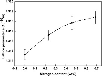
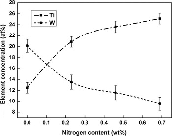
The cross-section of gradient cemented carbonitrides can be divided to be three zones: (i) the gradient layer; (ii) the bulk inside the gradient border; (iii) the inner bulk. In the paper, the cemented carbonitrides were tested by an x-ray diffractometer using Cu Kα target after gradient layers were removed. Because the penetration depth of the x-ray beam was less than 20 μm, the diffracting volume could be considered to be a measurement on the bulk inside the gradient layer. The lattice parameters of (Ti,W)C, i.e., the physical dimension of unit cells in a crystal lattice, were illustrated in Fig. 6. (Ti,W)C is the sodium chloride-typed face centered cubic (f.c.c) form (space group Fm3m, no. 225). As the nitrogen were increased, the lattice parameter of (Ti,W)C was elevated. According to the calculated nitrogen activity profiles, the nitrogen activity increased with the increase of nitrogen content. Reference Zhang, Du, Peng, Xie, Wen and Wang8 The nitrogen activity during sintering could affect the composition of (Ti,W)C cubic phase. Known from the isothermal section of Ti–W–C–N system, the W content in the cubic phase was expected to decrease with nitrogen activity increased. Reference Frykholm and Andrén17 In this paper, the W contents in (Ti,W)C diminished when more nitrogen was added. What's more, the titanium content increased in the bulk inside the gradient border as shown in Fig. 4. These trends were also confirmed by testing on the (Ti,W)C phase in the bulk inside the gradient border (in Fig. 7). The atom radium of tungsten is smaller than titanium (W: 1.35 Å, Ti: 1.4 Å), thereby the bond length of (Ti,W)C crystal lattice was extended when tungsten proportion was reduced and titanium proportion was raised.
Lattice parameters of (Ti,W)C with the nitrogen content.

Ti and W concentration with the nitrogen content.

C. Effects of nitrogen on the microstructure of bulks
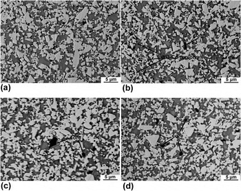
The microstructures of the inner bulks of all the samples were shown in Fig. 8. It could be observed that a small fraction of grains had black-cores in the gradient cemented carbonitrides. “Core” structures were often found in the microstructure of Ti(C, N)-based cermets containing other carbides such as Mo2C, TaC, NbC, VC, Cr3C2, HfC, etc. Reference Yang, Xiong, Zhang, Huang and Chen18–Reference Xu, Zhao, Ai, Qin, Wang and Huang21 It is usually believed that the cores are remnants of undissolved raw material such as Ti(C,N). Reference Lindahl, Gustafson, Rolander, Stals and Andrén22 During gradient sintering, the decrease of nitrogen activity near surface zone made the Ti(C,N) unstable, and therefore few of them remained after sintering. Reference Frykholm and Andrén17 In the inner bulk where the effect of gradient sintering was weak enough, Ti(C, N) could remain after sintering. There was no, or very slow diffusion of metal atoms in the cores during sintering, and therefore they would not be in equilibrium with the surroundings but kept their original composition. Reference Frykholm and Andrén17 Under the back scattered mode, the dark cores were impossible to separate from the binder phase according to the color contrast. However, they usually had a round or oval shape, and were surrounded by cubic phase. Most binders were found around WC phases while a few of binder were present among (Ti,W)C cubic phases. The (Ti,W)C cubic phase were commonly much larger than the binder. Moreover, most WC phases were separated by (Ti,W)C. There were only a few of pure WC-binder zones and no (Ti,W)C existed [in Fig. 8(b)], which was local inhomogeneous microstructure.
Microstructure of bulks of WC-(Ti,W)C-Ti(C,N)-Co cemented carbonitrides (a) 0 wt% N; (b) 0.23 wt% N; (c) 0.46 wt% N; (d) 0.69 wt% N.

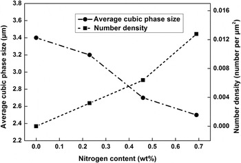
As could be found in Fig. 9, the number density of black cores increased when more nitrogen was added, indicating more Ti(C, N) were remained. Usually, WC phase is called α phase and (Ti,W)C cubic phase is called β phase. The average α-phase sizes were similar in the all materials in Fig. 8. However, for the β phase, there was evident difference that the β-phases were refined with nitrogen increased as shown in Fig. 9. Evidently, β-phase grain growth was impeded by nitrogen. There was a high affinity between titanium and nitrogen. The affinity could also be interpreted as the ability to form stable titanium–nitrogen bonds. When more nitrogen was added, the titanium diffusion was restrained by the affinity of nitrogen and therefore the dissolution and re-precipitation of (Ti,W)C were inhibited.
Number density of cores and average cubic phase size with the nitrogen content.

D. Effects of nitrogen on the transverse rupture strength
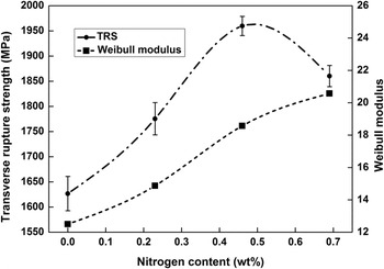
The transverse rupture strength (TRS) is shown in Fig. 10. TRS was improved with the nitrogen increased but it descended when overmuch Ti(C,N) was added. The gradient formation and thickening resulted in the increase of TRS. Cubic phase such as (Ti,W)C was so brittle that could not withstand any crack propagation. By contrast, Co binder phase with a better ductility could release the stress concentration in the crack tips by plastic deformation. Reference Liu, Wang, Long, Yang and Zhang23 A gradient layer was depleted of brittle cubic phase but abundant in ductile cobalt, and therefore it could absorb stress and resist against crack propagation. With the gradient layer thickness increasing, TRS was enhanced further. Nevertheless, when overmuch Ti(C,N) was added, a large number of Ti(C,N) remained in the inner bulk, and TRS was reduced since Ti(C,N) was brittle in essence. Reference Xiong, Guo, Yang, Xiong, Chen, Wu, Wen and Cao7 The TRS decreased at the highest nitrogen content (0.69%) compared with the value at 0.46% nitrogen. To understand the significance of this decrease, statistical analysis was conducted by confidence intervals. The confidence intervals of TRS for GN1, GN2, GN3 and GN4 were [1568.0, 1685.3], [1725.7, 1825.1], [1930.2, 1989.0], [1828.4, 1891.9] under the confidence level of 90%. It is indicated that there was 90% possibility that TRS of GN3 was higher than 1930 MPa while TRS of GN4 was lower than 1892 MPa. The TRS value of GN3 was higher >38 MPa than GN4 under 90% testing of different samples.
Transverse rupture strength and Weibull modulus with the nitrogen content.

Cemented carbonitrides are typical brittle ceramic-based composites, although the average value of TRS can give an indication of the measured TRS variation, it cannot quantify the scattered nature. Weibull distribution function is therefore used to quantify the effect of nitrogen content on the TRS.
The Weibull distribution function describing TRS can be formulated as following Reference Khalili and Kromp24 :
 $$P\left( \sigma \right) = 1 - \exp \left[ { - {{\left( {{\sigma \over {{\sigma _0}}}} \right)}^m}} \right]\quad .$$
P(σ) is the fracture probability of the material under the stress of σ; σ0 is a characteristic value of σ at which 63.2% of samples fail; m is the Weibull modulus. The bigger, the Weibull modulus is, the smaller, the variation of σ is, and vice versa. Equation (3) can be converted to another form:
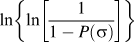
 $$\ln \left\{ {\ln \left[ {{1 \over {1 - P(\sigma )}}} \right]} \right\} = m\,\ln \,\sigma - m\,\ln \,{\sigma _0}\quad ,$$
where
 $\ln \left\{ {\ln \left[ {{1 \over {1 - P(\sigma )}}} \right]} \right\}$
can be plotted as a function of ln σ. The Weibull modulus is just the slope of straight line using the linear fitting method.
Reference Klein25
The correlation between the calculated Weibull modulus and the nitrogen contents was shown in Fig. 10. The trend of the relationship between the Weibull modulus and the nitrogen content was similar to that between the gradient layer thickness and the nitrogen content. For the gradient cemented carbonitrides, Weibull modulus actually reflected the consistency and stability of TRS. Evidently, the consistency and stability of the TRS increased with the gradient layer thicker.
As shown in Table III, the TRS of the gradient cemented carbonitride in this paper was compared with the ones reported in Refs. Reference Xiong, Guo, Yang, Xiong, Chen, Wu, Wen and Cao7 and Reference Liu, Wang, Long, Yang and Zhang23. Although more brittle cubic phases containing Ti were added in this paper, the TRS was higher than others. A key reason was that more Co was added, which improved the homogenous distribution of binder and the adhesive strength of interfaces between the hard phases. Besides, a small amount of metallic W was added to obtain reasonable carbon balance. It is noted that the preparation of gradient cemented carbonitrides in Ref. Reference Liu, Wang, Long, Yang and Zhang23 was more complicated and higher-cost than this paper.
Comparison of the transverse rupture strength of gradient cemented carbonitrides

E. Effects of nitrogen on the fractographs
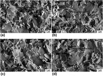
From a microstructural point of view, TRS of gradient cemented carbonitrides has fundamentally a close correlation with crack propagation. Figure 11 shows the fractographs of the homogeneous cemented carbide GN1 and the gradient cemented carbonitride GN3. There were mainly two modes reflecting fracture behavior, (i) intergranular fracture, i.e., the crack propagating along the interface between hard phase and binder, and (ii) transgranular fracture, i.e., the crack propagating through the brittle cubic phase. The fractured grains pointed by “transgranular fracture” in Fig. 11 were composed of W, Ti, C elements according to EDS test. This was transgranular fracture of (Ti,W)C cubic phases, which was commonly found in the near surface zones as well as the inner of GN1 and in the inner bulk of GN3. However, transgranular fracture was hardly found in the gradient layer of GN3 due to removal of this cubic phase. When cracks came across the brittle (Ti,W)C cubic phases, they tended to split the grains, and left river-like grooves on the fractured surface. There were only WC phase and binder in the gradient layer, and cracks propagated along interfaces between them by means of intergranular fracture. In this fracture mode, cracks had to deflect when encountering a well-developed grain. Thereby, the crack propagation path was extended, and more energy was dissipated. Cracks were more difficult to propagate by intergranular fracture mode. It is indicated that the gradient layers played an effective role in resisting against crack propagation.
Fractographs of homogeneous cemented carbide and gradient cemented carbonitride (a) the near surface zone of GN1; (b) the inner of GN1; (c) the gradient layer of GN3; (d) the inner bulk of GN3.

TRS improvement was accomplished by changing fracture mode in this paper. It is crucial to decrease the brittle phase and to increase ductile binder. There were some comparative examples of TRS improvement of cemented carbides to interpret this view. The fractured surfaces of WC-8Co cemented carbides with different (Cr0.8V0.2)2(C,N) contents were observed by Xie et al. Reference Xie, Liu, Ye, Li, Zhu and Fan26 When the (Cr0.8V0.2)2(C,N) content was more than 0.5 wt%, the addition of excessive V and Cr led to the formation of more (W,V)C brittle phases and increased the volume fraction of porosities in samples, which decreased the TRS of cemented carbides. By contrast, the brittle cubic (Ti,W)C depletion in the gradient layer was one factor that provoked the improvement of TRS in this paper. The fracture of coarse grained WC-8Co cemented carbides with different WC grain sizes was compared by Sun et al. Reference Sun, Su, Yang and Ruan27 The plastic deformation and rupture of the Co binder phase ligaments contributed the major portion of the dissipative work during the rupture of WC-Co cemented carbides due to its high value of the critical strain energy release rate. Reference Shatov, Ponomarev and Firstov28 Increase of Co mean free path with the coarsening grain size led to higher TRS. Similarly, the mean free path of the binder in the gradient layer was increased due to Co abundance, which consequentially was another factor that improved TRS in this paper.
IV. CONCLUSIONS
Gradient cemented carbonitrides were prepared by vacuum sintering in this paper. The effects of nitrogen on the microstructure, composition distribution and the rupture performance were systematically researched. The conclusions are summarized as follows:
-
(1) The thickness of the gradient layer is increased with more nitrogen added, and the area fraction of binder phase in the gradient layer increase with the gradient layer thicker due to more cobalt diffusion to the gradient layer. The maximum of titanium content in the bulk and the difference between the maximum and the nominal cobalt content are both enlarged with the nitrogen increased for the gradient cemented carbonitrides. Besides, the area fraction of WC is much higher in the gradient layer than in the bulk.
-
(2) As the nitrogen is increased, the lattice parameter of (Ti,W)C is elevated in the bulk inside the gradient border due to Ti increase and W decrease. For the gradient cemented carbonitrides, the number density of black Ti(C,N) cores increases when more nitrogen is added, and the (Ti,W)C phases are refined in the inner bulk.
-
(3) Transverse rupture strength is promoted due to gradient layer formation, but diminished after overmuch Ti(C,N) addition. Besides, the consistency and stability of TRS is enhanced with the gradient layer thicker. The transgranular fracture of (Ti,W)C cubic phases was commonly found in the homogeneous cemented carbides while hardly found in the gradient layer of gradient cemented carbonitrides. The gradient layers play an effective role in resisting against crack propagation.
ACKNOWLEDGMENTS
Support for this work by the Basic Research Programs of Sichuan Province (No. 2014GZ0086) and the China Scholarship Council (CSC) to support Tian'en Yang as a visiting PhD researcher in the School of Engineering, University of Hull are gratefully acknowledged.