I. INTRODUCTION
It is widely accepted that lithium-ion batteries (LIBs) have played important roles in many applications such as portable devices, electric vehicles, hybrid electric vehicles, and intelligent grids in recent years. Reference Stein1,Reference Yuan, Wang, Zhang, Hu, Chen, Huang and Goodenough2 Among a variety of cathode materials for LIBs, lithium iron phosphate (LiFePO4) is one of the most promising candidates and draws considerable attention. Olivine-structured LiFePO4 owns many strong advantages as follows: (a) high theoretical specific capacity (170 mA h g−1); (b) stable discharge voltage platform (3.4 V (vs. Li+/Li)); (c) relatively high tap density; (d) highly excellent thermal and cycling stability; (e) nontoxicity, harmless, safety, and environmental friendliness; and (f) abundant raw material resources and low cost. Reference Yuan, Wang, Zhang, Hu, Chen, Huang and Goodenough2–Reference Wang and Sun4 Nevertheless, its intrinsic weak points (poor electronic conductivity and ionic diffusivity) create obstacles to the application and development of LiFePO4. Reference Shin, Chung, Min, Byun, Jang and Cho5,Reference Wang, Wang, Wang, Park, Dou, Ahn and Kim6 To overcome the demerits, strategies have been put forward by researchers, such as conductive carbon coating, metal doping, and changing the size and morphology of the active particles. Reference Baster, Zheng, Zając, Świerczek and Molenda7–Reference Vu and Stein15 In particular, conductive carbon coating is a relatively effective way to improve the specific capacity and rate capability since the transport lengths of both electrons and ions would be shortened. Reference Ni, Liu and Fan16 Various sources of carbon, including carbon aerogel, glucose, multiwalled-carbon nanotubes, ascorbic acid, graphene, graphene oxide, and some organic solvents, have been used to decorate LiFePO4 to enhance its electrochemical performance. Reference Zhang, Liu, Qian, Zhao and Xu8–Reference Chi, Zhang, Cheng, Chen, Cao and Wan19 However, the current technology of conductive carbon coating still cannot meet the requirements for the materials with high electrochemical performance, especially as too much carbon loaded in the composites would seriously decrease the energy density. Reference Ni, Liu and Fan16 According to the literature, metal doping can give rise to the crystal lattice distortion, provide more space for intercalation/deintercalation of Li+, and hence improve the electrochemical performance of LiFePO4 as a cathode material. Reference Arumugam, Kalaignan and Manisankar20 If metal doping and carbon coating can be implemented concurrently to comodify LiFePO4, the electrochemical performance of the modified LiFePO4 would be enhanced significantly. Up to now, great efforts have been devoted to prove the thought. The electrochemical performance of LiFePO4 comodified with graphene and Mg2+ was improved greatly, which was reported by Bo Wang. Reference Wang, Xu, Liu, Liu, Guo, Wang, Wang, Xiong, Wang and Zhao21 The synthesis of nanostructured mixed orthophosphates LiMn y Fe1−y PO4/C with improved electrochemical performance was reported by Meligrana. Reference Meligrana, Di Lupo, Ferrari, Destro, Bodoardo, Garino and Gerbaldi22 Hongbo Shu found that the electrochemical performance of LiFePO4/C can be enhanced via codoping Ni and Mn in the composite. Reference Shu, Wang, Wu, Hu, Yang, Wei, Liang, Bai, Zhou, Wu, Chen, Wang and Jiang23 It should be pointed out that the carbon sources and doped metals introduced into the LiFePO4 materials were all independent in these literatures, which would make the preparation of the composites more complicated.
Exhilaratingly, the two factors (carbon sources and metals) can be provided simultaneously by using metal phthalocyanines (MPc) as modified additives to LiFePO4 in a proper action method. MPc with two-dimensional conjugate structure possess many excellent characteristics, such as oxidation–reduction ability, great stability, nontoxicity, and low cost. The characteristics of MPc enable them to be cathode replacing materials of LIBs. Reference Ramos-Sanchez, Callejas-Tovar, Scanlon and Balbuena24,Reference Yamaki and Yamaji25 In this paper, we report a moderate solvothermal process by using MPc or metal tetrasulfophthalocyanines (MPcTs) (M = Mn, Fe, Co, Ni, Cu, and Zn) as additives and followed by high-temperature calcination to in situ prepare LiFe1−x M x PO4/C (x ≈ 0.0040; M = Mn, Fe, Co, Ni, Cu, and Zn) composites which are used as cathode materials for LIBs for the first time. In the progress of the formation of the composites, MPc or MPcTs can provide carbon sources and metal at the same time. The morphologies and relevant electrochemical performance of all of the obtained products were studied. It is found that the effects of different MPc or MPcTs as additives on the electrochemical performance of LiFePO4 vary drastically, and in general, using MPcTs as additives is optimized for the improvement of specific capacity, reversibility, and cycling stability. The high-efficiency and inexpensive modifying method could be utilized to prepare more effective cathode materials for LIBs.
II. EXPERIMENTAL
A. Sample preparation
All the reagents and solvents were of analytical grade and used without further purification.
1. Synthesis of MPc and MPcTs
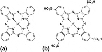
The MPc and MPcTs (M = Mn, Fe, Co, Ni, Cu, and Zn) (Fig. 1) were prepared by a microwave method according to the literature. Reference Kantekin, Dilber and Nas26,Reference Shaabani, Safari and Bazgir27
Structures of (a) MPc and (b) MPcTs (M = Mn, Fe, Co, Ni, Cu, and Zn).

2. Preparation of LiFe1−x M x PO4/C composites
Stoichiometric amounts of LiOH•H2O (AR, Aladdin), FeSO4•7H2O (AR, Aladdin), H3PO4 (AR) (3:1:1 in molar ratio), and C6H8O7•H2O (AR, Aladdin) were dissolved in a mixed solvent (H2O:DMF = 3:1, v/v) to form a homogeneous solution. The corresponding MPc or MPcTs were added to the solution (controlled a weight ratio of LiFePO4:MPc or LiFePO4:MPcTs as 20:1). The solution prepared above was being vigorously stirred for 1 h at the ambient temperature and transferred to a 60 mL Teflon-lined stainless steel autoclave for a solvothermal procedure at 170 °C for 24 h. After that, the reacted mixture was cooled down naturally to room temperature, filtered, and washed several times with distilled water until the pH value of the filtrate was equal to 7, and the SO4 2− anion in the filtrate could not be detected by BaCl2 solution. The resulting solvothermal precursors were collected and dried at 70 °C for 48 h, milled evenly, and followed by annealing under N2 atmosphere in a tubular furnace. The obtained powder was heat-treated to 350 °C with a heating rate of 1 °C min−1 and further heated up to 700 °C with a heating rate of 5 °C min−1, which maintained a dwell time of 3 h at each step. After being cooled to room temperature, the LiFe1−x M x PO4/C composites were finally obtained. Pure LiFePO4 (LFP) was prepared under the same conditions without any MPc.
The in situ synthesized LiFe1−x M x PO4/C composites using MPc (M = Mn, Fe, Co, Ni, Cu, and Zn) as additives are denoted as LFP-1, LFP-2, LFP-3, LFP-4, LFP-5, and LFP-6, and samples using MPcTs (M = Mn, Fe, Co, Ni, Cu, and Zn) as additives are denoted as LFP-7, LFP-8, LFP-9, LFP-10, LFP-11, and LFP-12, respectively.
B. Materials characterization
Thermogravimetric analysis (TGA) of the solvothermal precursor was carried out on a thermal analyzer (STA449C, Netzsch, Germany) in a temperature range of 40–900 °C at a heating rate of 10 °C min−1. The carbon content in the composites was determined by a C, H, N analyzer model 1106 Carol Erba Strumentazione. Inductively coupled plasma atomic emission spectrometry (ICP-AES, 2100DV, Perkin Elmer Corporations, Norwalk, CT) was used to measure the metal content of the prepared samples. Infrared (IR) spectrum was determined on an IR spectrometer (EQUINOX-55, Bruker Optics Inc., Karlsruhe, Germany) in the region of 400–4000 cm−1. Crystallinity and phase of the composites were detected by x-ray diffraction (XRD, D8 Advance, Bruker Inc., Germany) with a Cu Kα radiation in the 2θ range from 10° to 80° and a scanning rate of 0.03° min−1. The morphology and microstructure of the materials were characterized by scanning electron microscopy (SEM, Quanta 400 FEG, FEI Co., Netherlands) and high-resolution transmission electron microscopy (HRTEM, Tecnai G2 F20 S-TWIN, FEI Co., Netherlands) with an accelerating voltage of 15 and 200 kV, respectively.
C. Electrochemical assay
The electrochemical performance of the samples LFP-1–LFP-12 was tested in CR2025-type coin cells. The cathode was prepared as follows: Firstly, the active material (LFP-1–LFP-12 and LFP, respectively), acetylene black, and polytetrafluoroethylene (PTFE) were mixed in a weight ratio of 80:10:10. Secondly, the obtained slurry was rolled into a thin sheet by using a rolling machine and isopropyl alcohol as an auxiliary solvent, then the sheet was cut into square pieces and coated on nickel foam (16 mm diameters). Finally, the nickel foam with active material was pressed by a tablet machine, and the cathode of the LIB was obtained. Before being assembled in the battery, the as-prepared cathode was dried at 80 °C for 24 h in a vacuum drying oven to remove moisture and solvent. The active material loading of approximately 3 mg cm−2 should be ensured. After being dried, the cathode was assembled in the LIB in a glove box filled with argon, using a lithium metal (15.8 mm diameters) as an anode, polymer (Celgard2400) as a separator, and the solution of 1 M LiPF6 in 1:1 ethylene carbonate (EC)/diethyl carbonate (DMC) (LP30, Merck) as an electrolyte. The as-assembled battery was placed stationarily for 12 h before tested.
The relevant capabilities of the assembled batteries were investigated by using a charge/discharge instrument (Model CT2001A, Land Co., China) at 0.1 C for LFP-1–LFP-12 and pure LFP, and at different C-rates (0.1 C, 0.2 C, 1 C, 2 C, and 5 C) for LFP-4 and LFP-11 with the cut-off voltage range of 2.5–4.0 V. Moreover, the cyclic voltammetry (CV) curves and electrochemical impedance spectroscopy (EIS) plots of LFP-4, LFP-11, and pure LFP were detected by an electrochemical workstation (RST 5000, China). The CV measurement was performed in a voltage range of 2.5–4.2 V at a scanning rate of 20 mV s−1, and the EIS analysis was in the frequency range of 105–10−1 Hz at an applied amplitude of 10 mV. All the tests above were carried out at room temperature.
III. RESULTS AND DISCUSSION
A. TGA of solvothermal precursors
For investigating the stability of decorated LiFePO4 and the change during calcination, thermogravimetric (TG) measurements for solvothermal precursors of LFP-4 and LFP-11 were performed under nitrogen atmosphere in the range of 40–900 °C (Fig. S1 in the supporting document). The weight loss of LFP-4 precursor was about 28.57%, mainly taking place between 490 °C and ending at about 560 °C. And the weight loss of LFP-11 precursor was about 10% between 400 and 438 °C, after a short platform, it continues to lose weight until 610 °C, showing 36.82% weight loss in total. The results should be attributed to the decomposition of MPc and MPcTs in solvothermal precursors, as well as the abscission of the lattice water being originated from the reagents and solvents or the air. And above 800 °C, the residues were 65 and 61% for precursors of LFP-4 and LFP-11, respectively. The results suggest that LFP possesses a stable olivine structure, attesting that these composite materials can be used as cathode materials for LIBs and are still stable at the high temperature.
B. Elemental compositions, IR spectra, and structural and morphological characterization of the composite materials
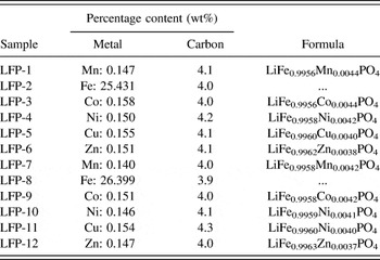
ICP-AES and elemental analysis were used to detect the elemental compositions of the materials, and the contents of carbon and metal doped in samples expressed in weight ratio are reported in Table I. All the samples deliver a carbon content of around 4.0%. The Fe content in LFP-2 and LFP-8 is distinctly more than others, because there is also a certain amount of Fe coming from pristine LiFePO4. It can be confirmed that the metal and carbon derived from MPc or MPcTs were successfully introduced into the composites and the general formula was obtained as LiFe1−x M x PO4/C (x ≈ 0.0040; M = Mn, Fe, Co, Ni, Cu, and Zn).
Metal and carbon contents as well as the formula of composite materials.

The IR spectra of all composites illustrate the characteristic peaks (Fig. S2 in the supporting document). The absorption peaks in the 944–965 cm−1 region are the symmetric stretching vibration of PO4 3−, at around 639 cm−1 are antisymmetric bending vibration of PO4 3−, and the absorption peaks of PO4 3− of symmetric bending vibration are at about 577 and 550 cm−1. The absorption peaks existed in 502 and 470 cm−1 should be assigned to the transfer of Li+, and the absorption peaks of C–O are found at about 1141 and 1061 cm−1. The results indicate that there are few organics remaining on the surface of samples, and the organic molecules are decomposed at high temperature to form carbon which disperses in the surface and interspace of the samples. The formed carbon is of great importance to the composite materials, because it can improve the electronic conductivity of particles inside the materials.
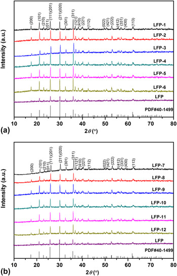
The XRD patterns of LFP-1–LFP-12 and pure LFP are presented in Fig. 2. The diffraction peaks show that all the obtained composites have a well-crystallized orthorhombic olivine structure with a space group of Pnma. The assignment of diffraction peaks is well consistent with the JCPDS card (No. 40-1499) and no obvious peaks of MPc or impurities (such as Fe2P, FePO4, LiPO4, or Fe2O3) appeared in the patterns. The results indicate that single phase products with high purity are delivered, and that the formation of amorphous carbon and doped metal coming from the pyrolysis of MPc or MPcTs in the LFP-1–LFP-12 composites does not change the crystal structure of these materials. It is noteworthy that the diffraction peaks of LFP-1–LFP-12 composites are all stronger than those of pure LFP, which indicates better crystallinity, suggesting that the crystallinity of LFP could be enhanced by using MPc or MPcTs as modified additives through the comprehensive utilization of a solvothermal technique and a high-temperature calcination method.
XRD patterns of (a) LFP-1, LFP-2, LFP-3, LFP-4, LFP-5, LFP-6, and pure LFP; (b) LFP-7, LFP-8, LFP-9, LFP-10, LFP-11, LFP-12, and pure LFP.

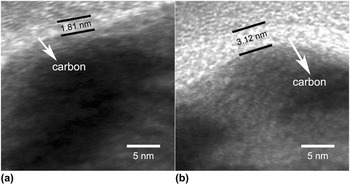
Figure 3 displays the SEM images of LFP-1–LFP-12. It can be observed that the morphologies of these samples vary significantly. The results demonstrate that the impacts of different MPc as modified additives on LFP are considerably diverse. That is mainly due to the action of different metals derived from MPc and MPcTs, though the content of doped metals in final composites is small. What is more, the sulfonic groups in MPcTs also have condign influence on the morphologies of the composites. Among all the samples, the grains of LFP-4 [Fig. 3(d)] and LFP-11 [Fig. 3(k)] possess smaller size and more homogeneous distribution, which indicates more improved electrochemical performance depending on reference. Reference Cho, Kim, Kim, Lim, Kim, Lee, Kang and Roh11 The diffusion of Li+ can be efficiently accelerated due to small particle size in LFP-4 and LFP-11, leading to higher ionic conductivities and more improved electrochemical performance. The grains of LFP-1 [Fig. 3(a)], LFP-3 [Fig. 3(c)], and LFP-12 [Fig. 3(i)] own larger size and more inhomogeneous distribution, which may be adverse to the improvement of the relevant electrochemical performance. The inferences were confirmed by the electrochemical assays for the LFP-1–LFP-12 composites. HRTEM was performed for further investigation of the carbon coated on LFP particles, and the images of LFP-4 and LFP-11 are shown in Figs. 4(a) and 4(b). It is obvious that amorphous carbon is successfully formed and effectively surrounds the LFP particles. The thickness of the full carbon-coating is about 1.81 nm for LFP-4 and 3.12 nm for LFP-11, respectively. Moreover, LFP-11 exhibits more homogeneous carbon layer coating on LFP particles, which make the contact between LFP and carbon better, resulting in faster Li+ diffusion and more enhanced electrochemical performance. The results should be attributed to the effect of sulfonic group in MPcTs during the solvothermal process.
SEM images of (a) LFP-1, (b) LFP-2, (c) LFP-3, (d) LFP-4, (e) LFP-5, (f) LFP-6, (g) LFP-7, (h) LFP-8, (i) LFP-9, (j) LFP-10, (k) LFP-11, and (l) LFP-12.

High-resolution TEM images of (a) LFP-4 and (b) LFP-11.

C. Electrochemical performances of the composite materials
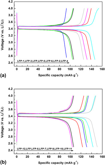
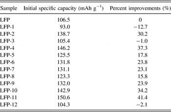
The electrochemical performances of samples LFP-1–LFP-12 were detected by using coin-type cells. The initial charge/discharge curves of all samples at 0.1 C-rate are shown in Fig. 5. It could be seen that the two series of composites exhibit similar charge/discharge platforms compared with LFP, which indicates that the addition of MPc or MPcTs does not influence the oxidation and reduction process of Li+. Reference Chung, Bloking and Chiang28,Reference Wang, Yang, Bewlay, Chen, Liu and Ahn29 All the charge/discharge profiles consist of charge and discharge plateaus at around 3.4–3.5 V, which could be the main characteristic of two-phase reaction based on the redox couple of Fe3+/Fe2+ during the process of extraction and insertion of Li+. The initial specific discharge capacities of samples are listed in Table II, and percent improvements of each material over pure LFP are obtained as well. It is observed from Fig. 5 and Table II that most of MPc and MPcTs additives could improve the discharge capacities of LFP. Compared with pure LFP, the specific discharge capacities of the composites are distinctly increased, except LFP-1, LFP-3, and LFP-12. In particular, LFP-4 and LFP-11 deliver optimized specific discharge capacities of 146.2 and 150.6 mA h g−1, respectively, which show preferred percent improvements of 37.3 and 41.4% based on pure LFP. It should be primarily attributed to the amorphous carbon and corresponding doped metal derived from MPc or MPcTs that makes the LFP particles interconnect with each other more easily and accelerates the transfer of the electrons between interfaces of the particles. It is worth mentioning that the electrochemical performances of LFP-7–LFP-12 are finer than those of LFP-1–LFP-6 on the whole. This result could be attributed to the introduced –SO3H in the MPcTs additives in the solvothermal process.
Initial charge/discharge curves at 0.1 C of (a) LFP-1, LFP-2, LFP-3, LFP-4, LFP-5, LFP-6, and pure LFP; (b) LFP-7, LFP-8, LFP-9, LFP-10, LFP-11, LFP-12, and pure LFP.

Initial discharge specific capacities of samples at 0.1 C and percent improvements of each composite based on pure LFP.

Compared with LFP, the specific discharge capacities of LFP-1, LFP-3, and LFP-12 drop a few (Fig. 5 and Table II), which should result from the larger size and less homogeneous distribution of their grains (Fig. 3). It is observed that LFP-4 and LFP-11 show the best electrochemical performances in each series in terms of initial specific discharge capacity (Fig. 5), which should be due to the superior electronic and ionic conductivity delivered from smaller size and more homogeneous distribution of the particles (Fig. 3), as well as the highest carbon content of two composites in each series, respectively (Table I). The results confirm the inferences in the SEM section and demonstrate that the size, the morphology, and the carbon content of these composites have great effect on the electrochemical performances. The effect of carbon and metal content originated from MPc on the performance of the kind of composites will be further excavated in our laboratory.
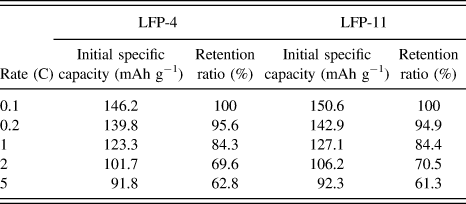
As a consequence, LFP-4 and LFP-11 were chosen as subjects for further discussions. The discharge profiles at each discharge rate of both LFP-4 [Fig. 6(a)] and LFP-11 [Fig. 6(b)] exhibit a smooth platform at about 3.4 V, and the flat voltage plateaus are gradually shortened with no obvious drop from 0.1 to 5 C. Table III displays the specific capacities at various C-rates and rate capacity retention ratios of LFP-4 and LFP-11 compared to 0.1 C. According to Fig. 6 and Table III, samples using NiPc and CuPcTs as additives have enhanced rate capability. Moreover, the specific discharge capacity of LFP-11 is higher than that of LFP-4 at each rate. The preferable rate capabilities suggest the faster lithium ion diffusion and higher electronic conductivity, which is attributed to the introduction of the additives.
Initial discharge curves of (a) LFP-4 and (b) LFP-11 at various C-rates.

Initial discharge specific capacities and capacity retention ratios of LFP-4 and LFP-11 compared to 0.1 C at different rates.

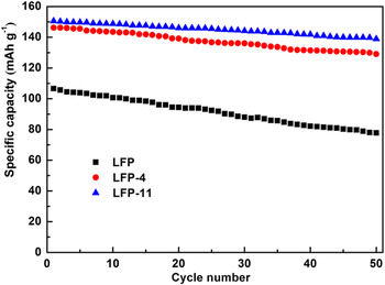
To evaluate the cycling stabilities of samples LFP-4 and LFP-11, the specific capacity of 50 cycles for LFP-4, LFP-11, and pure LFP was investigated (Fig. 7). At the rate of 0.1 C, the specific capacity of pure LFP was decreased from 106.6 to 77.8 mA h g−1 after 50 cycles, which delivered a capacity retention ratio of 73.0%, corresponding to 88.2% of LFP-4 (from 146.2 to 129.0 mA h g−1) and 92.2% of LFP-11 (from 150.6 to 138.9 mA h g−1). It is obvious that the specific capacities of LFP-4 and LFP-11 are both higher than those of pure LFP. Especially, LFP-11 exhibits a distinct advantage of cycling performance, and it displays more stable discharge capacity retention than LFP-4 or pure LFP, though slightly capacity fading is still existed. Amorphous carbon derived from CuPcTs and substantially improved diffusion rate of Li+ should be the main reasons for the phenomenon. This result is in agreement with the rate performance, further indicating that MPc, especially MPcTs, could significantly improve the cycling stability of LFP.
Cycling stabilities of LFP-4, LFP-11, and pure LFP.

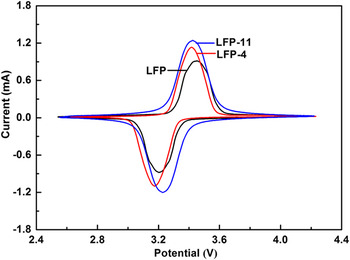
Figure 8 compares the CV curves of LFP-4, LFP-11, and pure LFP in the first cycle. As seen from the CV profiles, the oxidation peaks and reduction peaks of the three samples are highly symmetric, which means great two-phase reaction for redox couple of Fe3+/Fe2+ and excellent reversibility of Li+ intercalation/deintercalation in the electrode. Reference Qin, Wu, Zhao, Ma and Wang30 The oxidation and reduction peaks of LFP-11 are located at 3.42 and 3.23 V, respectively, with the polarization of 0.19 V. As for LFP-4, the oxidation and reduction peaks are at 3.42 and 3.18 V, and the polarization is 0.24 V. While the pure LFP possesses a pair of oxidation and reduction peaks of 3.46 and 3.20 V, respectively, which delivers the largest polarization of 0.26 V. Both of the polarization values of LFP-4 and LFP-11 are less than that of pure LFP, which manifests that LFP-4 and LFP-11 can present better reversibility and reactivity. Reference Miao, Bai, Jiang, Sun and Wang31 This is primarily attributed to the carbon layer coated on them derived from NiPc and CuPcTs, which can enhance the conductivity and reversibility of LiFePO4 particles. Besides, the peaks of LFP-4 and LFP-11 are sharper than that of pure LFP, which is mainly because of the higher electrochemical reactivity due to the faster diffusion of Li+, smaller polarization, and lower inner resistance. Reference Qin, Wu, Zhao, Ma and Wang30 The improved capabilities are all derived from adding NiPc and CuPcTs in the original samples.
CV curves of LFP-4, LFP-11, and pure LFP.

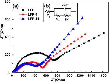
EIS was measured to further investigate the impact of MPc and MPcTs on the kinetics process of the electrode materials. Figure 9 shows EIS plots and equivalent circuit of LFP-4, LFP-11, and pure LFP. In the very high-frequency region [Fig. 9(a)], an intercept at Z′-axis interprets the ohmic resistance [corresponding to R s in Fig. 9(b)] of electrode, separator, and electrolyte. Reference Andre, Meiler, Steiner, Wimmer, Soczka-Guth and Sauer32 The charge transfer resistance [corresponding to R ct in Fig. 9(b)] is reflected by semicircle in the high-middle frequency region, the smaller diameter of semicircle brings about the lower R ct of electrode material, which is related to electrochemical reaction at interparticle contact and interface of electrode/electrolyte. Reference Chen, Wu and Kong33 The Warburg impedance [corresponding to W in Fig. 9(b)] is presented by the inclined line in the low-frequency region, which relates to the diffusion rate of Li+ from the electrolyte to the bulk electrode, higher slope of the line results in lower Warburg impedance. Reference Lin, Pan, Gao and Liu34 As is obviously displayed in EIS plots, LFP-4 and LFP-11 deliver much lower R ct (534 Ω for LFP-4 and 401 Ω for LFP-11) than pure LFP (743 Ω), and the W of LFP declined after decorated by MPc or MPcTs. As a result, the total electric resistance is lower, and the electrochemical properties are more excellent. LFP-11 indicates the lowest resistance, suggesting that the electrolyte–electrode complex reactions can be taken place easily. This should be ascribed to the shortening of Li+ diffusion distance and increasing of ionic conductivity by smaller particle size and homogeneous distribution with introduced substituent group –SO3H in CuPcTs. The results suggest that the total resistance of the Li-ion battery can be decreased by the additives of MPc and MPcTs, which is consistent with the characteristics described above.
EIS plots (a) and equivalent circuit (b) of LFP-4, LFP-11, and pure LFP.

IV. CONCLUSION
In summary, we have created a solvothermal procedure with MPc as additives to modify LiFePO4 for the first time followed by high-temperature calcination to successfully in situ prepare LiFe1−x M x PO4/C (x ≈ 0.0040) composites used as electrode materials for Li-ion batteries. In this approach, the as-synthesized samples using MPc as additives exhibit excellent electrochemical performance, including higher specific capacity, lower impedance, better rate capability, reversibility, and cycling stability. Particularly, LFP-11 displays a specific capacity of 150.6 mA h g−1 at 0.1 C and 92.3 mA h g−1 while the discharge rate rises to 5 C, which is the highest among all the samples. In addition, its capacity retention reaches to 92.2% after 50 cycles. So LFP-11 performs optimum electrochemical characteristics, which meet the demands of high-performance batteries. This method that adopts MPc as additives may also be used for other cathode materials.
ACKNOWLEDGMENTS
The authors thank the National Natural Science Foundation of China (Nos. 21401149 and 21371143), the National Basic Research Program (973 Program 2013CB934001), “Science and Technology plan project of Xi'an City [No. CXY1438(6)], Key Laboratory Research and Establish Program of Shaanxi Education Section (No. 11JS112), and Special Foundation of Shaanxi Education Section (No. 12JK0603) for the financial support of this work.