I. INTRODUCTION
Recently, nanoindentation has been used to probe small-scale mechanical properties, which are relevant to a wide range of materials and applications. The response of a material to nanoindentation is usually presented in the form of a load–displacement curve. When metallic materials undergo irreversible permanent deformation, discrete physical events, such as dislocation nucleation,Reference Gerberich, Nelson, Lilleodden, Anderson and Wyrobek1–Reference Begau, Hartmaier, George and Pharr18 dislocation source activation,Reference Shim, Bei, George and Pharr14, Reference Barnoush, Welsch and Vehoff15 phase transformation,Reference Ahn, Oh, Kim, Oh, Bei, George and Han16, Reference Pharr, Oliver and Clarke19–Reference Lee, Kim and Han30 and mechanically induced twinning,Reference Bradby, Williams, Wong-Leung, Swain and Munroe31, Reference Misra, Zhang, Jia, Somani and Karjalainen32 can be detected as discontinuities on nanoindentation load–displacement curves. Among these, we consider here just the onset of plasticity resulting from dislocation nucleation or dislocation source activation, which can produce geometrical softening accompanied by a sudden displacement excursion in the very early stage of mechanical contact during load-controlled nanoindentation, an event referred to in the literature as a “pop-in.”
Geometrical softening can also occur as a result of yield point phenomena manifested as yield drops followed by propagation of Lüders strain in the early part of the tensile stress–strain curves of body-centered cubic metals. A mechanism for this was first proposed by CottrellReference Cottrell33 wherein dislocations that are trapped by solute atmospheres break free simultaneously at the upper yield point and multiply, causing instantaneous softening and a sharp yield drop. Then, when the load is removed after plastic deformation and the specimen allowed to rest, the solute atoms diffuse to the dislocations as time passes, a process that can occur even at room temperature in the case of relatively mobile solutes such as interstitial carbon atoms. This causes the dislocations to be locked up again by the solute atoms, resulting in a decrease in the mobile dislocation density and a reappearance of the yield point, a phenomenon that is referred to as strain aging.Reference Cottrell33
Because both pop-ins during nanoindentation and yield drops during tensile testing are manifestations of strain softening, they may be related to each other at a fundamental level despite their very different length scales. This article provides experimental evidence of their close relationship in a ferritic steel by investigating mechanical responses at the macro- and nano-scales using tensile testing and nanoindentation, respectively.
II. EXPERIMENTAL PROCEDURE
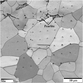
The material used in this study was a cold-rolled plate of a ferritic steel with the chemical composition Fe–0.06C–0.08Si–0.16Mn–0.02Al–0.0006N–0.01Cr (wt%) that was fully annealed at 1053K. An electron backscattered diffraction (EBSD) system (HKL Nordlys Channel 5) was used for the identification of phases, grains, and their boundaries on polished surfaces. The specimens were prepared by a standard metallographic grinding and polishing procedure finishing with 0.25-μm diamond suspension followed by electropolishing with a 10% perchloric acid–90% ethanol solution to remove the mechanically damaged layer. The volume fractions of the phases were determined to be approximately 99% ferrite and 1% pearlite based on optical microscopy images and the combined band contrast and slope mapReference Ahn, Um, Choi, Kim, Oh, Kim and Han34–Reference Kim, Ahn, Park, Oh and Han36 obtained from EBSD measurements, as shown in Fig. 1. The average grain size of the ferrite was 21 μm, which is large enough to avoid interference by grain boundaries during nanoindentation.
A combined electron backscattered diffraction band contrast and slope map for the fully annealed steel specimen showing majority ferrite grains, isolated (∼1%) pearlite colonies, and an 8 × 8 array of indentations. Only those indents that were located squarely within the ferrite grains and away from the boundaries were analyzed in this study.

Macroscopic deformation behavior was investigated by uniaxial tensile tests at a constant strain rate of 1.3 × 10⁻³ s−1 using plate-type ASTM standard subsize specimens.37 Initially, the specimens were loaded to 6% nominal strain and unloaded. Then the specimens were strain aged for various times at room temperature and reloaded to determine the aging time at which the yield point reappeared.
Nanoindentations were made using a Hysitron Tribolab nanoindentation system (Hysitron, Inc., Minneapolis, MN) operated in load control at a constant loading rate of 200 μNs−1 up to a maximum load of 1000 μN. A Berkovich type indenter with a half angle of 65.3° was used. To investigate the relationship between pop-in behavior and yield point phenomena, four sets of tests were performed: just before, right after, 30 h after, and 3 weeks after the 6% tensile prestrain. For each of these conditions, a total of 64 indentations were made in an 8 × 8 array with 4 μm spacing between the indents, as shown in Fig. 1. Based on the EBSD band contrast map, only those indentations that were located in the ferrite grains far enough away from the grain boundaries were selected for analyses to exclude any grain boundary effect on the load–displacement curves.Reference Ohmura and Tsuzaki11, Reference Soer, Aifantis and De Hosson38, Reference Lilleodden and Nix39 To ensure that all of specimens have the same surface condition before the nanoindentations, they were prepared by a standard metallographic grinding and polishing procedure.
III. RESULTS AND DISCUSSION
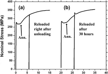
Figure 2 presents the stress–strain curves obtained from uniaxial tensile tests of the steel. For the fully annealed specimen, a sharp yield point is clearly observed. After the initial elastic portion, a significant yield drop occurred at the upper yield point, followed first by Lüders strain propagation and then uniform elongation accompanied by work hardening. In the case of specimens that were deformed to 6% nominal strain, unloaded, and then reloaded, their behavior depended on the strain aging time. When reloaded right after unloading, the material did not show a clear yield drop, as shown in Fig. 2(a). In contrast, a sharp yield point was observed when the specimen was reloaded after 30 h of strain aging, as shown in Fig. 2(b). These results are typical of yield point phenomena seen in steels.
Comparison of the uniaxial tensile stress–strain curves for the annealed steel specimen (arrows) with those obtained after (a) loading to 6% strain, unloading, and then immediately reloading and (b) loading to 6% strain, unloading, strain aging for 30 h, and then reloading. The curves in (b) are offset from the origin for clarity of presentation.

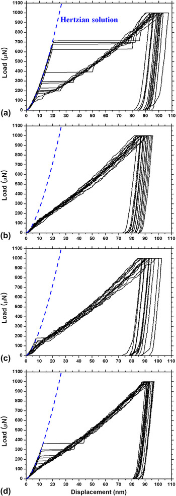
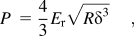
Interestingly, similar behaviors were also observed in the nanoindentation tests. Figures 3(a)–3(d) show the load–displacement curves for nanoindentations performed before, right after, 30 h after, and 3 weeks after 6% prestrain. Before the prestrain (i.e., annealed state), large and obvious pop-ins were observed on the loading curves for most of the indentations at quite high loads (100–700 μN), as shown in Fig. 3(a). In this study, a sudden displacement excursion larger than 3 nm was defined as a pop-in. Before the first pop-in, the initial elastic portion of the loading curves can be fitted to the Hertzian elastic contact solutionReference Johnson40 assuming that the indenter tip is spherical at shallow depths:
Nanoindentation load–displacement curves obtained (a) before, (b) right after, (c) 30 h after, and (d) 3 weeks after 6% tensile prestrain. In (a), (c), and (d), the experimental data (black lines) before the pop-ins match well the theoretical Hertzian elastic contact solution (blue dashed lines). In (b), the deformation is elastic–plastic practically right from the start.

where P is the load applied by a spherical indenter, δ is the corresponding indentation depth, R is the radius of the indenter tip, and E r is the effective (or reduced) modulus of indentation. The radius of the indenter tip R was determined to be 1 μm from a calibration using standard fused quartz. Assuming isotropic elasticity, E r can be calculated from the relation between the elastic constants of the sample and indenter:
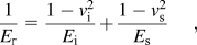
where v and E are the Poisson’s ratio and Young’s modulus, respectively, and the subscripts “” and “s” refer to the indenter and sample, respectively. By substituting values of the room-temperature elastic constants of ferrite (E s = 208.2 GPa and v s = 0.29)Reference Lee41 and diamond (E i = 1141 GPa and v i = 0.07) into Eq. (2), E r was determined to be 189.7 GPa. Finally, the theoretical elastic behavior during indentation was calculated using E r and R (=1 μm), and the results are plotted as the blue dashed lines in Fig. 3. Before the first pop-ins, the experimental loading curves match the theoretical curve well, indicating elastic response before pop-in.
The maximum shear stress underneath the indenter, τ m, can also be calculated from Hertzian analysisReference Johnson40:
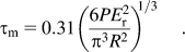
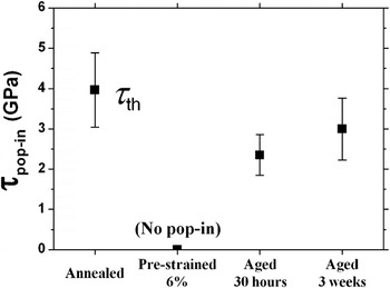
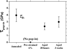
Using the above equation, τ m at pop-in (τ pop-in) for the annealed specimen was determined to be in the range 3.3–5.3 GPa, which corresponds to G/25–G/15 where G, the shear modulus of ferrite at room temperature, is 80.7 GPa.Reference Lee41 These values of τ pop-in are within the range of values for the theoretical strength (τ th) of a crystalline material,Reference Honeycombe42 indicating that the pop-ins in the annealed specimen are likely the result of dislocation nucleation. Based on a total of 14 indents that were located squarely within the ferrite grains, the average value of τ pop-in for the annealed steel was found to be 3.96 ± 0.92 GPa (Table I), which corresponds to ∼G/20. Similar results were obtained previously for annealed Ni single crystals,Reference Shim, Bei, George and Pharr14 where it was found that the pop-in stresses during nanoindentation with small radius spheres were in the range of the theoretical strength (∼G/14). Note that, although the average τ pop-in values are comparable to the theoretical strength, there are indent-to-indent variations, which may be due to thermal fluctuationsReference Bei, Gao, Shim, George and Pharr13, Reference Schuh and Lund43 or surface imperfections.Reference Gerberich, Venkataraman, Huang, Harvey and Kohlstedt44, Reference Kramer, Yoder and Gerberich45
Maximum shear stress at pop-in in (τ pop-in) for annealed, prestrained, and strain-aged conditions. No distinct pop-in was observed on prestrained specimen.

Figure 3(b) shows representative load–displacement curves for nanoindentation tests performed right after the prestrain. No distinct pop-in was observed on any of these curves. Instead, most of the curves showed only a slight change of slope without a clear pop-in to mark the onset of plasticity. The transition loads were relatively low, less than 100 μN, indicating elastic–plastic deformation practically right from the start of indentation in the prestrained specimen.
Figures 3(c) and 3(d) show the nanoindentation load–displacement curves obtained 30 h and 3 weeks after the prestrain, respectively. In both cases, distinct pop-ins reappeared for some of the indentations, while they were never observed when the specimen was indented right after the prestrain. Moreover, as shown in Figs. 3(b)–3(d), the pop-in loads increased with increasing strain aging time.
For the pop-in loads shown in Fig. 3, the maximum shear stresses under the indenter (τ pop-in) were calculated as discussed earlier. Figure 4 shows these calculated pop-in stresses (average values ± 1 standard deviation) for the annealed, prestrained, and strain-aged conditions. The annealed specimen pops-in at the theoretical strength, consistent with the notion that plastic deformation of dislocation-free volumes requires nucleation of dislocations. After 6% tensile prestrain, however, the pop-ins disappear, indicating that, if there are enough mobile dislocations in the stressed volume, plastic deformation can occur by movement of these pre-existing dislocations at very low loads (essentially right from the start of deformation) rather than by the nucleation of new dislocations at very high stresses. These results are consistent with earlier results, which showed that the frequency of pop-in occurrence can be dramatically reduced by mechanically altering the surface,Reference Bahr, Kramer and Gerberich3, Reference Oliver and Pharr46 i.e., as a result of dislocation-induced damage. Similarly, it has been shown that the pop-in stresses decreased with increasing prestrain and indenter sizeReference Shim, Bei, George and Pharr14 suggesting that it is easier to activate pre-existing dislocations than it is to nucleate new ones.Reference Goken and Kempf7, Reference Page, Oliver and McHargue21 As has been discussed before, pop-in loads depend on the initial dislocation density in the highly stressed zone underneath the indenter.Reference Shim, Bei, George and Pharr14, Reference Barnoush, Welsch and Vehoff15, Reference Lee, Yu, Baek and Nahm47 If the density of the pre-existing mobile dislocations is high and the radius of the spherical indenter tip is much larger than the dislocation spacing, movement of dislocations will, in general, occur at lower applied stresses than those needed for dislocation nucleation, resulting in lower values for the pop-in stresses.
Nanoindentation pop-in stresses before, right after, 30 h after, and 3 weeks after the 6% tensile prestrain.

What has not been investigated until now is the effect of interstitial solute atoms on pop-in behavior. At the macroscopic scales of tensile tests, the origin of the sharp yield point is known to be dislocation locking by interstitial solute atoms, the so-called Cottrell atmosphere.Reference Cottrell33 To free a dislocation from this atmosphere, additional stress over that normally required for dislocation movement is needed resulting in a sharp yield drop after the dislocations break free and multiply. We find here that an analogous situation exists in the case of nanoindentation where the softening is manifested as a pop-in. Immediately after the 6% prestrain, the steel has a high density of new dislocations, which are relatively mobile because they have not yet been pinned by the solute atoms. Therefore, both the sharp yield points [Fig. 2(a)] and the distinct pop-ins [Fig. 3(b)] disappear. However, when the solute atoms diffuse to the dislocations as the aging time increases, they tend to anchor the dislocations again, which results in a recovery of the yield point phenomenon [Fig. 2(b)]. When a nanoindentation is made near a location where the dislocations are pinned, a higher stress is needed to unlock them. This causes a reappearance of the pop-in (clear elastic-to-plastic transition). Additionally, if we assume that the longer the strain aging time, the higher the probability of making an indent near a pinned dislocation, then it stands to reason that the pop-ins would occur more frequently and at higher loads with increasing aging time, as shown in Fig. 3(d). Together, these nanoindentation and tensile test results strongly suggest that the pop-in behavior in ferrite is closely related to its yield point phenomenon.
IV. CONCLUSIONS
This study investigated the relationship between pop-in behavior during nanoindentation and yield point phenomena in tensile tests by comparing the mechanical responses of prestrained and strain-aged ferritic steel. The pop-ins observed on the load–displacement curves of the annealed specimens (i.e., before tensile prestraining) were attributed to dislocation nucleation based on Hertzian analyses. Their disappearance right after prestraining and reappearance after strain aging, similar to the disappearance and reappearance of yield drops in tensile tests, strongly suggest that nanoindentation pop-ins in ferritic steel are closely related to their yield points. Both phenomena are influenced by dislocation locking by solutes (Cottrell atmospheres).
ACKNOWLEDGMENTS
This study was supported by National Research Foundation of Korea grant funded by the Ministry of Education, Science and Technology (2010-0018936). CSO is thankful for the support by a grant from the Fundamental R&D Program for Core Technology of Materials funded by the Ministry of Knowledge Economy, Republic of Korea. EPG was supported by the Materials Sciences and Engineering Division, Basic Energy Sciences, U.S. Department of Energy.