I. INTRODUCTION
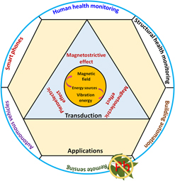
Energy harvesting implies conversion of available energy in the surroundings into electrical energy. There are many abundant energy sources in the environment, such as vibration, magnetic field, wind, solar, wave, thermal energy, etc., which can be harvested to generate electrical energy.Reference Maurya, Yan, Priya, Xu and Kobayashi1,Reference Priya, Song, Zhou, Varghese, Chopra, Kim, Kanno, Wu, Ha Dong, Ryu and Polcawich Ronald2 The harvested electrical energy can be used for powering the Internet of Things (IoT) components, wireless sensor nodes, portable medical devices, RFID tags, mobile electronics, control electronics in smart civil structures, etc., as schematically shown in Fig. 1. Considering the abundance of the stray vibrations and magnetic field and their relevance in the emerging field of the IoT for powering wireless sensor nodes, in this review, we focus on these two energy sources. Out of various choices for harvesting vibration energy, piezoelectric materials are the dominant choice under low strain conditions. For magnetic fields, piezoelectric–magnetostrictive composites have emerged as the promising materials. In both these cases, most of the demonstrated energy harvesters utilize lead (Pb)-based piezoelectric materials, which may contain up to 60 wt% lead. There is an increasing environmental concern that Pb from these products could escape into the atmosphere during high-temperature processing, and could also contaminate ground water, if the devices are not properly disposed. Thus, significant focus in recent times has been on developing lead-free piezoelectric materials with high transduction coefficients. Development of lead-free energy harvesters will provide a practical pathway for deployment of power sources for the IoT.
Schematic of various applications of the energy harvesting from stray vibrations and magnetic field, using lead-free piezoelectric and magnetostrictive materials.

It is interesting to note that ferroelectric–piezoelectric materials can be used for harvesting energy from a diverse set of sources, such as temperature fluctuations, solar radiation, biomechanical movements, ocean waves, mechanical vibrations, etc. For example, piezoelectric nanogenerators (PNGs) and nanocomposites can be used to harvest energy from biomechanical/human motion.Reference Siddiqui, Kim, Duy, Nguyen, Muhammad, Yoon and Lee3 Specially designed flexible Eel-like piezoelectric harvestersReference Wu, Wang and Xie4 and piezoelectric bimorphs can be used for harvesting wave energy.Reference Mehmood, Abdelkefi, Hajj, Nayfeh, Akhtar and Nuhait5,Reference Xie, Wang and Wu6 Pyroelectric effects have been used to harvest cyclical temperature fluctuations, unlike thermoelectric materials which harvest temperature gradients.Reference Yang, Guo, Pradel, Zhu, Zhou, Zhang, Hu, Lin and Wang7 Ferroelectric/piezoelectric materials have shown promise for harvesting solar energy using the depolarization electric field.Reference Brody and Crowne8,Reference Paillard, Bai, Infante, Guennou, Geneste, Alexe, Kreisel and Dkhil9 However, in this review, we limit ourselves to harvest stray vibrations and magnetic field using piezoelectric materials and composites. Building upon the excellent progress made by the global research community in advancing the science of piezoelectric energy harvesting, here we review various strategies that can play a relevant role in enhancing the performance of lead-free piezoelectric material-based harvesters. This review provides an overview on various vibration and magnetic field energy harvesting strategies that will be important in design of harvesters with higher output power. The direct piezoelectric effect is primarily used in the vibration energy harvesting,Reference Hyunuk Kim, Priya, Priya and Inman10 by coupling external mechanical excitation with the piezoelectric materials implemented on resonating structures.Reference Hyunuk Kim, Priya, Priya and Inman10 In addition to the coupling parameter under various vibration modes (primarily bending modes), output power also depends on the ability of the piezoelectric material to withstand an applied force and its ability to repeatedly undergo a recoverable strain.Reference Bowen, Kim, Weaver and Dunn11 Emphasis in this review will be on synthesis strategies of high-performance lead-free piezoelectric materials and composites for high density energy harvesting using stray vibrations and magnetic field. First, we discuss fabrication strategies for lead-free piezoelectric materials followed by their application in energy harvesting. Detailed discussion is provided on sources of vibration and magnetic field followed by various strategies for designing high-performance energy harvesters targeting these sources. Lastly, we review strategies for the performance assessment and efficiency enhancement of the energy harvesters.
II. STRATEGIES FOR FABRICATING HIGH-PERFORMANCE LEAD-FREE MATERIALS FOR ENERGY HARVESTING
In this section, we summarize main strategies utilized for achieving enhanced piezoelectric response.
A. Compositional modification
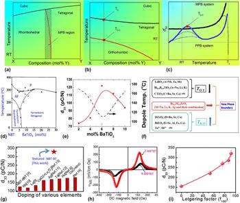
The compositional design strategies include identifying formulation in the vicinity of the morphotropic phase boundary (MPB) and polymorphic phase transition (PPT) using elemental substitution (dopant engineering). Exploiting MPB [Fig. 2(a)] in a binary or higher order system has been a well-known strategy toward achieving enhanced piezoelectric response. Conventionally, the MPB in a phase diagram represents the region with two coexisting phases.Reference Liu and Ren12 The MPB exhibits instability of the polarization states, allowing easy rotation of the polarization vector by applying external stress or electric field. The PZT system exhibits MPB between the rhombohedral PbZrO3 and tetragonal PbTiO3 end members. Several diffraction and theoretical calculations of the MPB compositions have indicated the relationship between an intermediate monoclinic/orthorhombic phase and enhanced piezoelectric response. This intermediate phase was considered to bridge the end members (tetragonal and rhombohedral phases) of the phase diagram. According to Fu and Cohen,Reference Fu and Cohen13 for a low symmetry phase (e.g., monoclinic), the polarization can easily adjust along the applied electric field providing strong coupling between degrees of freedom for polarization and crystallographic strain leading to enhanced piezoelectric properties. Therefore, the MPB composition of PZT has been extensively investigated due to its superior functional response, which was conventionally attributed to the coexistence of two phases (or presence of the bridging monoclinic/orthorhombic phase) and enhanced domain reorientation.Reference Jaffe14–Reference Guo, Cross, Park, Noheda, Cox and Shirane16 For example, on applying electric field along the pseudocubic [001] direction of rhombohedral PZN-PT having polarization vector along pseudocubic [111], the zero field rhombohedral state irreversibly changes first to an monoclinic MC phase, and then to an orthorhombic phase with a m = c m.Reference Noheda, Cox, Shirane, Park, Cross and Zhong17 (1 − x)Na0.5Bi0.5TiO3–xBaTiO3 (NBT–BT), a well-known lead-free piezoelectric material was found to exhibit a narrow MPB at 6–7% of BT, unlike the broad MPB in PZT-based materials. The NBT-based materials also exhibited enhanced performance at the MPB, however, inferior to the MPB-based composition of PZT.
Characteristic (hypothetical) phase diagrams for perovskite solid solutions exhibiting (a) MPB or (b) PPT. The resulting temperature dependence of the piezoelectric coefficient (c) hypothetical MPB and PPT materials with the same RT piezoelectric coefficient and same Curie temperature (T C), where dotted trend lines indicate degradation of piezoelectric properties due to depolarization at temperatures near T O–T and T C. Adapted from Ref. Reference Leontsev and Eitel18. (d) Phase diagram of (1 − x)(Bi1/2Na1/2)TiO3–xBaTiO3 (NBT–BT) reported by Takenaka et al. Reprinted with permission from Ref. Reference Takenaka, Maruyama and Sakata24, The Japan Society of Applied Physics. (e) Variation of the piezoelectric constant and transition temperature (ferroelectric to antiferroelectric phase mentioned as depolarization temperature) as a function of BaTiO3 concentration in the NBT–BT system. Reprinted with permission from Ref. Reference Bichurin, Petrov, Zakharov, Kovalenko, Yang, Maurya, Bedekar and Priya37. (f) Diagram for constructing new phase boundaries in KNN-based ceramics. Reprinted with permission from Ref. Reference Wu, Xiao and Zhu39. (g) Piezoelectric response of textured NBT–BT as compared to other compositionally modified NBT–BT-based compositions. (h) ME response of the ME composite containing textured NBT–BT piezoelectric component. (i) Variation in the piezoelectric response of textured NBT-based materials with respect to the degree of texturing. Reprinted with permission from Ref. Reference Maurya, Zhou, Yan and Priya58.

The PPTs are ferroelectric to ferroelectric phase transitions. Figure 2(b) shows PPT from the tetragonal to orthorhombic (T O–T) phase, which differs from the MPB in two significant ways: (i) The boundary at the PPT exists between two ferroelectric phases over a wider range of composition, as compared to a narrower phase boundary at the MPB and (ii) the PPT boundary exists at a much lower temperature than the Curie temperature over a wide range of composition; however, the MPB exists all the way from low temperature until T C. It is worthwhile to mention that the tricritical point marked on the phase diagram in Fig. 2(b) has been investigated extensively because the piezoelectric properties exhibit maximum values.Reference Leontsev and Eitel18 Researchers have shown that the local maximum piezoelectric point can be shifted toward room temperature (RT) by elemental modifications. This strategy has been widely used in improving the piezoelectric response of lead-free (K,Na)NbO3 (KNN) ceramics by modulating T O−T through elemental substitution.Reference Zhang, Xia and Shrout19 The temperature dependent behavior of PPT has been considered similar to the composition dependent behavior of MPB.Reference Shrout and Zhang20 Both the PPT and MPB lead to improvements in the piezoelectric properties. However, the piezoelectric properties of a MPB system are rather temperature-independent as compared to a PPT system, as shown in Fig. 2(c). Furthermore, the dopant engineering can be effectively used to tailor piezoelectric properties of the MPB (e.g., for PZT) and PPT (e.g., for KNN-based materials) compositions.Reference Kimura, Ando, Maurya, Priya and Uchino21,Reference Yan, Priya, Kim, Randow and Sano22 In following sections, we review compositional modification strategies for some of the well-known lead-free piezoelectric materials.
Out of several different piezoelectric systems, K0.5Na0.5NbO3 (KNN), Bi0.5Na0.5TiO3 (NBT), and Ba(Ti0.8Zr0.2)O3–(Ba0.7Ca0.3)TiO3 (BCZT) systems have recently emerged as potential lead-free candidates.Reference Liu and Ren12,Reference Rödel, Jo, Seifert, Anton, Granzow and Damjanovic23 KNN-based systems exhibit promising piezoelectric properties but have been difficult to be synthesized due to a narrow sintering window. Moreover, KNN-based compounds require Nb precursors (e.g., Nb2O5), which are relatively expensive.Reference Rödel, Jo, Seifert, Anton, Granzow and Damjanovic23 Ba(Ti0.8Zr0.2)O3–(Ba0.7Ca0.3)TiO3 was found to show enhanced piezoelectric properties but had a low Curie temperature (<93 °C).Reference Liu and Ren12 Next, we mainly discuss compositionally modified derivatives of NBT and KNN and different strategies for achieving enhanced functional response.
1. NBT-based compositions
NBT and its solid solutions with various tetragonal compounds including K1/2Bi1/2TiO3 (KBT), BaTiO3, CaTiO3, SrTiO3, and PbTiO3 have been investigated extensively.Reference Takenaka, Maruyama and Sakata24–Reference Takenaka, Sakata and Toda27 Takenaka et al.Reference Takenaka, Maruyama and Sakata24 presented the phase diagram of NBT–BT showing the existence of a MPB, as shown in Fig. 2(d). The d 33, k 33, and loss tangent factors for NBT–6% BT composition were found to be ∼125 pC/N, 0.55, and 0.013, respectively. However, T C and ferroelectric to antiferroelectric transition temperature (T d, also referred as depoling temperature) decreased at MPB. On modifying with BiScO3 and BiFeO3, the NBT-based solid solution resulted in enhanced T C of NBT and NBT–BT up to 400 °C, along with higher remnant polarization (P r).Reference Marchet, Boucher, Dorcet and Mercurio28–Reference Nagata, Koizumi, Kuroda, Igarashi and Takenaka30 Li et al.Reference Li, Chen, Zhou, Xu, Sun and Xu31 reported the dielectric and piezoelectric response of (1 − x)(Na0.5Bi0.5)TiO3–xNaNbO3 ceramics. Samples in the composition range of 0.01–0.02 exhibited d 33 ∼ 80–88 pC/N. The nonstochiometry of Na in Bi0.5Na0.5−xTiO3 ceramics played a major role in changing its functional response through microstructure modulation.Reference Sung, Kim, Cho, Song, Kim, Chong, Park, Do and Kim32 The value of d 33 was enhanced from 74 pC/N (T d ∼ 190 °C) at x = 0.0–91 pC/N (T d ∼ 112 °C) with increasing Na deficiency up to a certain extent. The effect of bismuth excess was studied on NBT–BT ceramics near the MPB. One of the compositions exhibited a large P r ∼ 37.5–41.1 µC/cm2 and d 33 ∼ 171–176 pC/N at RT with moderate depoling temperature (T d) ∼ 85 °C.Reference Xu, Huang, Chen, Chen, Liu and Kim33 Wang et al.Reference Wang, Tang and Chan34 studied ternary systems, with (0.95 − x)(Bi1/2Na1/2)TiO3–x(Bi1/2K1/2)TiO3–0.05BaTiO3 (x = 0–20 mol%) compositions. The composition with x = 5 mol% was found to exhibit d 33 ∼ 148 pC/N, k p ∼ 34%, k t ∼ 49.2%, and T d ∼ 125 °C. However, these modifiers also enhanced the magnitude of the coercive field (E c), which made poling difficult. Generally, the values of E c and T d have been found to be lower in doped materials; however, cobalt doping increased T d by 20 °C.Reference Chu, Chen, Li and Yin35,Reference Xu, Chen, Chen, Liu, Kim and Ahn36 High piezoelectric properties in these Bi-based compounds have been mostly accompanied by the lowering of T d, as shown in Fig. 2(e).Reference Bichurin, Petrov, Zakharov, Kovalenko, Yang, Maurya, Bedekar and Priya37 NBT–BT with 4% Li doping has been found to exhibit a decent piezoelectric response of d 33 = 176 pC/N, k 33 = 0.6, and T d = 171 °C.Reference Takenaka, Nagata and Hiruma38 Please note that, in the case of NBT-based lead-free piezoelectric materials, the effect of doping has not been very successful, in contrast to lead-based systems, where a d 33 > 700 pC/N can be achieved by appropriate elemental modification (doping). However, depending on the temperature, targeted compositional modification of NBT-based materials could be used for lead-free piezoelectric vibration energy harvesting.
2. KNN-based materials
KNN-based systems utilize the polymorphic phase boundary (PPB), and their properties can be modified by modulating PPT. On susbstituting isovalent dopants (Li+ on the A-site and Sb5+/Ta5+ on the B-site of KNN), the transition temperatures (T R–O, T O–T, and T C) of KNN can be modified.Reference Wu, Xiao and Zhu39 Li+ was found to decrease T O–T, along with an increase in T R–O and T C of KNN. However, the susbstitution of Sb5+/Ta5+ on the B-site was found to decrease both T O–T, and T C, along with an increase in T R–O. Therefore, the substitution of Li+, Ta5+, and Sb5+ can be used to shift these three types of phase transitions to achieve the desired piezoelectric response through modulation of the phase boundaries.Reference Wu, Xiao and Zhu39 Isovalent doping also has the advantage of not creating defects, thereby, avoiding domain wall pinning, which could be helpful in achieving enhanced functional response. The higher electronegativity of Ta5+ and Sb5+ was also considered to play a major role in enhanced functionality of modified KNN, due to the increased covalent nature of their bonds with Nb5+.Reference Gao, Zhang, Qing, Tan, Zhang and Hao40
On the other hand, aliovalent substitution at the Nb5+ site can be used as an effective method for achieving desired functional response. Mostly, the functional response of modified materials is controlled through the doping-induced point defects. The accepter dopant has been found to result in the formation of a defect dipole, inhibiting the domain wall motion and exhibiting a hardening behavior. Copper-doped KNN exhibited two kinds of defect complexes with oxygen vacancies,  ${\left( {{\rm{Cu}}_{{\rm{Nb}}}^{{\rm{II}}{{\rm{I}}^\prime }} - V_{\rm{o}}^{{\rm{ \bullet \bullet }}}} \right)^\prime }$, and
 ${\left( {V_{\rm{o}}^{{\rm{ \bullet \bullet }}} - {\rm{Cu}}_{{\rm{Nb}}}^{{\rm{II}}{{\rm{I}}^\prime }} - V_{\rm{o}}^{{\rm{ \bullet \bullet }}}} \right)^{\rm{ \bullet }}}$.Reference Erünal, Jakes, Körbel, Acker, Kungl, Elsässer, Hoffmann and Eichel41,Reference Eichel, Erünal, Jakes, Körbel, Elsässer, Kungl, Acker and Hoffmann42 For Mn-doped KNN crystals, the resistivity increased rapidly after annealing due to the increased valence of Mn2+ by absorbing electron holes.Reference Cheng, Wu, Lou, Wang, Wang, Xiao and Zhu43 In a similar fashion, Mn2+ absorbed the free carrier holes generated due to volatization of alkali elements in Mn2+-doped KNN films. This resulted in enhanced functional response of Mn-doped KNN films.Reference Wang, Ren, Shi, Chen, Wu and Yao44 The substitution of Ti4+-generated holes and oxygen vacancies, both substantially could affect dielectric properties.Reference Goh, Yao and Chen45 Furthermore, W6+ was substituted at the Nb5+ site, creating point defects and restraining formation of oxygen vacancies as:
 $V_{\rm{o}}^{{\rm{ \bullet \bullet }}} = W_{{\rm{Nb}}}^{{\rm{ \bullet \bullet }}} + 6O$.Reference Wu, Zhu, Liu, Shi, Zheng, Huang and Fang46 On the other hand, Ba2+, Pb2+, and Dy3+ were substituted aliovalently at the A-site to modify the functional response by creating a suitable defect structure and microstructure.Reference Hagh, Jadidian, Ashbahian and Safari47–Reference Peddigari, Thota and Pamu49 In KNN-based materials, the enhanced piezoelectric response is mainly achieved by modulating the phase boundary, which can be further perturbed by other factors including the formation of defects. Based on various studies on modified KNN-based ceramics, Wu et al.Reference Wu, Xiao and Zhu39 summarized modifiers/dopants and their effect on phase transitions, as shown in Fig. 2(f).
B. Anisotropy-based improvement of piezoelectric response
The piezoelectric properties are anisotropic, i.e., different crystallographic orientations have varying piezoelectric response. Therefore, one can fabricate oriented single crystals to achieve enhanced piezoelectric response depending on their crystallographic symmetry. The crystal symmetry dictates possible domain variants in a ferroelectric material, which in turn influences the piezoelectric response of a system.Reference Zhang and Li50 Interestingly, some crystals exhibit enhanced piezoelectric response, when poled in nonpolar axis orientation. This so-called domain-engineered state is used for controlling domain configuration. Relaxor-PbTiO3 crystals with engineered domain configurations were found to exhibit an enhanced piezoelectric coefficient (>2000 pC/N) and electromechanical coupling factor k 33 (∼0.9), due to ease of polarization rotation under applied electric (E) fields along the nonpolar direction.Reference Park and Shrout51 Single crystals with different crystal structures exhibit different kinds of domain-engineered states.Reference Zhang and Li50 For example, rhombohedral relaxor-PbTiO3 single crystals exhibit eight degenerate domain variants, having spontaneous polarization along one of the 〈111〉 directions. On poling along the nonpolar axis [001], four out of eight domain variants become energetically favorable under the poling E-field, having polar vectors along [111],  $\left[ {\bar{1}11} \right]$,
 $\left[ {1\bar{1}1} \right]$, and
 $\left[ {\bar{1}\bar{1}1} \right]$ directions. Therefore, in a poled sample, four domain variants exist with polar vectors inclined along the poling direction (∼54.7°). This domain-engineered configuration is stable because of the absence in the driving force for the domain motion (only polarization rotation or inclination). This results in enhanced piezoelectric response and hysteresis-free strain characteristics, with low dielectric loss in the relaxor-PT crystals. For higher magnitudes of the applied E-field, polarization inclination toward [001] collapses along the [001] direction, resulting in a structural transition to the tetragonal phase.Reference Zhang and Li50,Reference Park and Shrout51
The domain-engineered state in piezoelectric single crystals was found to exhibit enhanced piezoelectric response as discussed above. For example, 0.96Na0.5Bi0.5TiO3–0.04BaTiO3 single crystals exhibited enhanced piezoelectric response for 〈001〉 orientation.Reference Zhang, Zhang, Wang, Wang, Lin, Zhao, Luo, Ge and Viehland52 Similarly, 0.92Na0.5Bi0.5TiO3–0.08K0.5Bi0.5TiO3 (NBT–KBT) lead-free piezoelectric single crystals also exhibited enhanced piezoelectric response in the 〈001〉 orientation.Reference Sun, Zhao, Zhang, Fang, Zhang, Li, Lin, Wang and Luo53 The alternative to single crystals for achieving enhanced piezoelectric response is to texture the piezoelectric materials in the desired crystallographic orientation. The texturing process is scalable and cost-effective. This process does not require a special furnace or Pt crucible. Moreover, textured polycrystalline materials have higher mechanical strength as compared to their single crystal counterparts. Considering these advantages, it is remarkable to achieve single crystal-like properties in polycrystalline textured ceramics, which have their grains oriented in a single preferred crystallographic direction.Reference Messing, Trolier-McKinstry, Sabolsky, Duran, Kwon, Brahmaroutu, Park, Yilmaz, Rehrig, Eitel, Suvaci, Seabaugh and Oh54–Reference Yan, Zhou and Priya57 The synthesis of textured ceramics was performed by aligning anisotropic shaped seed templates in the powder matrix using a tape casting process, along with the schematic of the texturing process.Reference Maurya, Zhou, Yan and Priya58 At high temperature, epitaxial growth occurs on the seed template, resulting in a textured grain growth. Here, we limit our discussion to the fabrication of textured (grain-oriented) ceramics and solid state single crystal growth method, considering their closely related synthesis mechanism and scalability.
1. Textured lead-free piezoelectric materials
As discussed in previous sections, the piezoelectric properties are anisotropic, which means high piezoelectric response can be achieved in certain crystallographic orientations. The Curie temperature (T C) [or the depoling temperature (T d)] limits the temperature range of operation of piezoelectric devices. Pb(ZrTi)O3 (PZT)-based ceramics have been dominating the piezoelectric industry due to superior piezoelectric responses and high T C ∼ 390 °C.Reference Wolf and Trolier-McKinstry59 The functional response of PZT can be easily tuned by elemental substitution with slight shift in T C, as discussed earlier. However, elemental substitution was not effective in lead-free piezoelectrics, and mostly elemental substitution was found to reduce T C and T d toward lower temperatures.Reference Wang, Tang and Chan34,Reference Zuo, Ye, Fang and Li60–Reference Sung, Kim and Coondoo62 The low values of T C and T d limit the temperature stability of the system, hindering their commercial exploitation.Reference Guo, Gu, Luo, Liu and Withers63–Reference Ren68 One successful approach in overcoming the challenge has been synthesis of textured materials.
Synthesis of textured lead-free piezoelectric NBT–BT ceramics has been quite challenging due to various constraints, including the presence of volatile alkali elements, chemical reactivity with seeds, poor sinterability of the base matrix compositions, and cubical grain shape. These fundamental problems were solved to achieve degree of texturing >90% and a 2× improvement in d 33 (as compared to the randomly oriented ceramics having the same composition).Reference Maurya, Zhou, Yan and Priya58 The textured ceramics exhibited d 33 ∼ 322 pC/N as compared to d 33 ∼ 160 pC/N for its randomly oriented counterpart, as marked in Fig. 2(g).Reference Maurya, Zhou, Yan and Priya58 To demonstrate the superiority of textured lead-free piezoelectric materials, magnetoelectric (ME) composites were fabricated, which exhibited a 3× improvement in the ME response [Fig. 2(h)]. The piezoelectric response of the textured material increases consistently with increasing degree of texturing (Lotgering factor), as shown in Fig. 2(i). The enhanced piezoelectric response in textured polycrystalline ceramics was comparable to single crystal values having similar composition and PZT-based ceramics (PZ27 Ferroperm).Reference Zhang, Zhang, Wang, Wang, Lin, Zhao, Luo, Ge and Viehland52,Reference Wenwei, Hong, Xiangyong, Bijun, Xiaobing, Feifei, Dan, Ping, Xiaoming, Di and Haosu69
Previous efforts on the texturing of NBT-based ceramics had limited success.Reference Kwon, Sabolsky, Messing and Trolier-McKinstry70 For texturing NBT-based ceramics, plate-type NBT seeds with high aspect ratio were synthesized. The texturing process imparts epitaxial growth on the NBT template seeds aligned in the base matrix powder. These NBT seeds with shape anisotropy were synthesized using the topochemical microcrystal conversion method, from Bi4Ti3O13 platelets. On heating the ceramic tapes containing NBT seeds, epitaxial growth occurred at the 〈001〉pc/〈012〉Rh oriented surface of the templates.Reference Maurya, Zhou, Yan and Priya58 The coherent and defect-free interface between NBT seeds and the textured grain facilitated the domain wall motion with coherent domain switching and exhibited a lower coercive field. This textured NBT–BT material had near MPB composition and therefore exhibited lower T d.
To achieve enhanced thermal stability, a composition on the tetragonal side in the phase diagram of the K0.5Bi0.5TiO3–BaTiO3–Na0.5Bi0.5TiO3 (KBT–BT–NBT) system was textured.Reference Maurya, Zhou, Wang, Yan, Li, Viehland and Priya71 This textured composition resulted in a large E-field induced strain with an ultra-low degree of hysteresis. These ternary textured lead-free ceramics exhibited enhanced low field piezoelectric response (d 33) and high temperature stability (>160 °C). The temperature dependence of the relative permittivity and loss tangent measurements for textured samples indicated T d ∼ 165 °C. The temperature-dependent d 33 measurements were performed for textured and nontextured samples, which further indicated high temperature stability (∼165 °C) for textured samples. Nontextured samples exhibited stable d 33 up to 200 °C but had lower magnitude.Reference Maurya, Zhou, Wang, Yan, Li, Viehland and Priya71 The grain-oriented lead-free ternary K0.5Bi0.5TiO3–BaTiO3–Na0.5Bi0.5TiO3 (KBT–BT–NBT) piezoelectric ceramic showed ∼70% increase in d 33. The properties of some of the textured piezoelectric materials are listed in Table I.
〈001〉 oriented textured and SSCG grown lead-free piezoelectric materials.

To provide understanding of processing–microstructure–property relationships in textured materials, phase field modeling has been used.Reference Yan, Zhou, Maurya, Wang and Priya72,Reference Zhou, Yan, Priya and Wang73 Recent reviews on phase field models and applications can be found in the literature.Reference Chen74,Reference Chen75 Quantitative relationships between templated grain growth processing, texture development, and dielectric and piezoelectric properties in textured ferroelectric polycrystals and the underlying responsible mechanisms have been investigated. It has been found that while the degree of crystallographic texture generally increases with the increasing template volume fraction, it is the average distance between template seeds that plays an important role. Thus, reducing the template seed size and shortening the seed distance is an effective way to achieve higher texture at lower template volume fraction.Reference Zhou, Yan, Priya and Wang73 The competing effects of the crystallographic texture and template seed volume fraction on the dielectric and piezoelectric properties of the textured ferroelectric template-matrix polycrystals were further investigated. It is found that while the crystallographic texture significantly improves the polycrystal properties, a higher volume fraction of template seeds results in reduced electromechanical properties, consequently cancelling the advantage of texturing in the ferroelectric system. This competing detrimental effect was attributed to the composite effects of mechanical clamping and charge accumulation at template–matrix interfaces.Reference Zhou, Yan, Priya and Wang73
The transduction coefficient is an important parameter in the selection of piezoelectric materials. The magnitude of the transduction coefficient is governed by the product of piezoelectric strain constant (d) and the effective piezoelectric voltage constant (g). This can be understood by considering the electric energy available under an alternating stress excitationReference Priya95:
 $$P = {U_{\rm{e}}} = {1 \over 2}C{V^2} = {1 \over 2}{\varepsilon _0}{\varepsilon _{\rm{r}}}{A \over t}{\left( { - {{g \cdot F \cdot t} \over A}} \right)^2} = {1 \over 2}\left( {d \cdot g} \right) \cdot {\left( {{F \over A}} \right)^2} \cdot \left( {At} \right)\quad ,$$
or energy density (u e),
 $${u_{\rm{e}}} = {1 \over 2}\left( {d \cdot g} \right) \cdot {\left( {{F \over A}} \right)^2}\quad ,$$
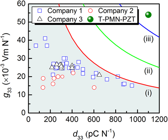
where F is the applied force, A is the area, and t is the thickness of the active piezoelectric material. Equation (1) demonstrates that under given experimental conditions, a material with a higher (d·g) product is expected to generate higher power.Reference Priya95 At resonance, the consideration of electromechanical coupling and mechanical quality factor becomes important for an energy harvester. For example, Yan et al. fabricated textured Pb(Mg1/3Nb2/3)O3–PbZrO3–PbTiO3 (PMN–PZT) ceramics and demonstrated enhanced piezoelectric properties (d 33 > 1000 pC/N, g 33 > 50 × 10−3 Vm/N and tan δ < 1.2%).Reference Yan, Cho, Maurya, Kumar, Kalinin, Khachaturyan and Priya96 Generally, high d 33 piezoelectric materials exhibit a low value of g 33 and vice versa (Fig. 3). This behavior was observed due to the fact that the d 33 is mostly proportional to the square root of the dielectric constant of the piezoelectric materials. Interestingly, the textured PMN–PZT ceramics exhibited both high d 33 and high g 33 values due to the template-controlled dielectric characteristics. The textured ceramic exhibited a giant d 33 of 1100 pC/N, which was 4.8 times higher than that of its randomly oriented counterpart having d 33 ∼ 230 pC/N. Therefore, texturing could be used to achieve high energy density piezoelectric materials for high density vibration energy harvesting. The computational study demonstrated that 〈001〉-texturing can be exploited to achieve a giant piezoelectric voltage coefficient g 33 in PbTiO3 ceramics, where the piezoelectric strain coefficient d 33 was maximized and dielectric permittivity ε33 was minimized, yielding maximized g 33 = d 33/ε33.Reference Yan, Zhou, Maurya, Wang and Priya72 These computational results were in good agreement with the complementary experiments.Reference Yan, Zhou, Maurya, Wang and Priya72,Reference Zhou, Yan, Priya and Wang73 In another approach to achieve a high value of (d 33·g 33) in polycrystalline piezoelectric materials, Ahn et al.Reference Ahn, Choi, Ryu, Yoon, Hahn, Kim, Choi and Park97 proposed a composition design rule. This rule indicated that the enhanced value of d 33·g 33 can be obtained by tuning the magnitude of the atomic weight ratio between A and B sites (R w = W A/W B) in ABO3 perovskite ceramics. Various materials were synthesized to confirm the design rule for achieving an enhanced d 33·g 33 value. It was suggested that to obtain an enhanced value of d 33·g 33, along with optimum R w, the crystallographic phase must be taken into account.
Comparison of g 33 and d 33 values of various piezoelectric ceramics. Different colored lines (i), (ii), and (iii) indicate the plots of g 33 d 33 = c function; (i) c = 16,500 × 10−15 m2/N, (ii) c = 30,000 × 10−15 m2/N, and (iii) c = 50,000 × 10−15 m2/N. Reprinted with permission from Ref. Reference Yan, Cho, Maurya, Kumar, Kalinin, Khachaturyan and Priya96.

2. Solid-state single crystal growth for enhanced piezoelectric response
The reduction of defects associated with grain boundaries, strong anisotropy, and chemical homogeneity in single crystals can provide exceptional properties (electrical, optical, and mechanical) as compared to polycrystalline materials. The quality of the single crystal can play an important role, which depends on the purity of the initial raw materials, growth conditions and fabrication method, and crystallographic orientation of the crystals. Conventionally, single crystals have been fabricated using methods such as liquid to solid and vapor to solid phase transformation.Reference Holden, Singer and Morrison98,Reference Gilman99
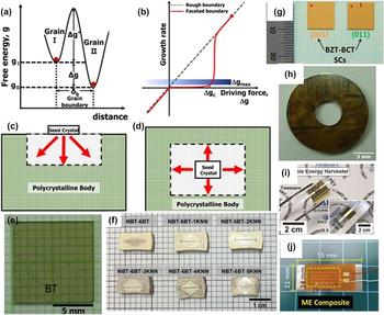
Recently, solid to solid conversion from polycrystals to single crystal has attracted great attention due to its cost-effectiveness and scalability.Reference Lee and Ye100,Reference Kang, Park, Ko and Lee101 The solid-state crystal growth (SSCG) method has advantages over the other conventional piezoelectric single crystal growth methods, such as uniformity, chemical homogeneity, and net-shape production. Also, this method is well-suited for single crystal growth of materials with volatile elements, incongruent melting points, and wide solubility ranges. The SSCG method is based on the abnormal grain growth (AGG) phenomenon, in which a bigger grain or a seed crystal consumes all other grains in polycrystals, converting a polycrystalline body to a stoichiometric single crystal.Reference Kang and Kang102 AGG is governed by the grain boundary structure and driving force (∆g) for the grain boundary migration. The parameter, ∆g, is the difference in free energies of two adjacent grains [Fig. 4(a)] and the maximum driving force (∆g max) for the growth is nearly equal to the maximum value of the larger grain in the system. AGG occurs in the system with faceted grain boundaries rather than the rough grain boundaries, due to the nonlinear relationship between driving force and migration kinetics [Fig. 4(b)].Reference Ryu, Kang, Zhou, Choi, Yoon, Park, Choi, Hahn, Ahn, Kim, Kim, Priya, Lee, Jeong and Jeong103–Reference An, Yoon, Chung and Kang105 In faceted grain boundary migration, the growth rate is small for the grains with lower ∆g values. When ∆g is equal to a critical driving force ∆g c (≤∆g max), a substantial grain growth occurs and the larger grain in the system continuously grows and thus the AGG behavior occurs.Reference Kang, Lee and An106 The ∆g max in a system can be governed by the average grain size and grain size distribution, whereas ∆g c changes with the temperature, dopant (vacancy) concentration, and surrounding atmosphere.Reference Jung and Kang107,Reference An and Kang108 Therefore, by appropriate control of ∆g max and ∆g c, the desired microstructure in the polycrystals could be obtained [Fig. 4(b)]. The conversion from polycrystals to single crystal takes place by suppressing the grain growth of polycrystals (∆g max < ∆g c) and through occurrence of grain growth on the seed crystal without impingement of other matrix grains (∆g seed > ∆g c). The commercial solid-state conversion method is schematically depicted in Figs. 4(c) and 4(d).Reference Ryu, Kang, Zhou, Choi, Yoon, Park, Choi, Hahn, Ahn, Kim, Kim, Priya, Lee, Jeong and Jeong103 In this method, a seed crystal with known crystallographic orientation is diffusion bonded to the polycrystalline material or embedded within the powder compact followed by the heat treatment process. During the heat treatment process, the interface of the seed crystal continuously grows, thereby converting the polycrystalline body into a large single crystal. The complete/congruent melting of the main components is not involved and the crystal growth occurs through a seed crystal. The solid-state conversion efficiency could be enhanced by applying a temperature gradient or using a seed crystal with surface defects such as twins and dislocations.
Schematics showing the (a) energy state of atoms, g I and g II, on the surfaces of two adjacent grains, ∆g*: activation energy for atom diffusion across the boundary; ∆g: the driving force for atom diffusion, (b) relation between boundary migration and grain growth, and solid-state conversion of single crystals by (c) diffusion bonding and (d) embedding of a seed crystal. Reprinted with permission from Ref. Reference Kang, Park, Ko and Lee101. (e–h) Various lead-free single crystals. (e) and (h) Reprinted with permission from Ref. Reference Kang, Park, Ko and Lee101, (f) AIP Advances 6, 015310 (2016); used in accordance with the Creative Commons Attribution (CC BY) license.Reference Park and Kang116 (g) Reprinted with permission from Ref. Reference Palneedi, Annapureddy, Lee, Choi, Choi, Chung, Kang and Ryu117 (i) and (j) applications of single crystals, fabricated by the solid-state single crystal growth method. (i) and (j) Reprinted with permission from Refs. Reference Hwang, Byun, Jeong and Lee119 and Reference Annapureddy, Kim, Palneedi, Lee, Choi, Yoon, Park, Choi, Hahn, Ahn, Kim, Jeong and Ryu114, respectively.

The SSCG technique has emerged as a cost-effective and scalable technique for producing the piezoelectric single crystals.Reference Lee and Ye100 By using this technique, lead-based piezoelectric single crystals such as Pb(Mg1/3Nb2/3)O3–PbTiO3 (PMN–PT) and Pb(Mg1/3Nb2/3)O3–Pb(Zr,Ti)O3 (PMN–PZT) are commercially fabricated.Reference Kimura, Ando, Maurya, Priya and Uchino21 Lead-free piezoelectric single crystals based on compositions BaTiO3 (BT),Reference Yamamoto and Sakuma109 K0.5Na0.5NbO3,Reference Fisher, Benčan, Kosec, Vernay and Rytz110–Reference Fisher, Benčan, Bernard, Holc, Kosec, Vernay and Rytz112 (Na1/2Bi1/2)TiO3–BaTiO3–(K1/2Na1/2)NbO3,Reference Park, Lee and Kang113–Reference Park and Kang116 and 82BaTiO3–10BaZrO3–8CaTiO3Reference Palneedi, Annapureddy, Lee, Choi, Choi, Chung, Kang and Ryu117 were also successfully fabricated. Figures 4(e)–4(h) show lead-free piezoelectric single crystals fabricated using the SSCG method.Reference Ryu, Kang, Zhou, Choi, Yoon, Park, Choi, Hahn, Ahn, Kim, Kim, Priya, Lee, Jeong and Jeong103 The single crystals produced by SSCG have been used in applications such as ME composites and flexible PNGs, as shown in Figs. 4(i) and 4(j).Reference Annapureddy, Kim, Palneedi, Lee, Choi, Yoon, Park, Choi, Hahn, Ahn, Kim, Jeong and Ryu114,Reference Hwang, Yang, Yang, Lee, Lee, Park, Han, Lee, Jeong, Kim, Park and Lee118,Reference Hwang, Byun, Jeong and Lee119 In Table I, the properties of some of the prominent lead-free piezoelectric single crystals grown using the solid-state conversion method are listed. The SSCG method and texturing of piezoelectric materials are especially promising due to their cost-effectiveness and scalability. Also, the enhanced piezoelectric constant of textured and solid-state grown single crystals can be used to fabricate efficient energy harvesters. Next, we discuss about vibration and magnetic field sources, and strategies for harvesting them.
III. VIBRATION AND MAGNETIC ENERGY SOURCES, AND STRATEGIES FOR ENERGY CONVERSION
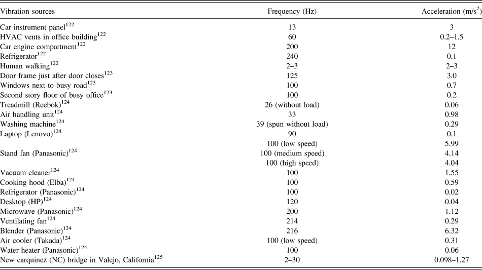
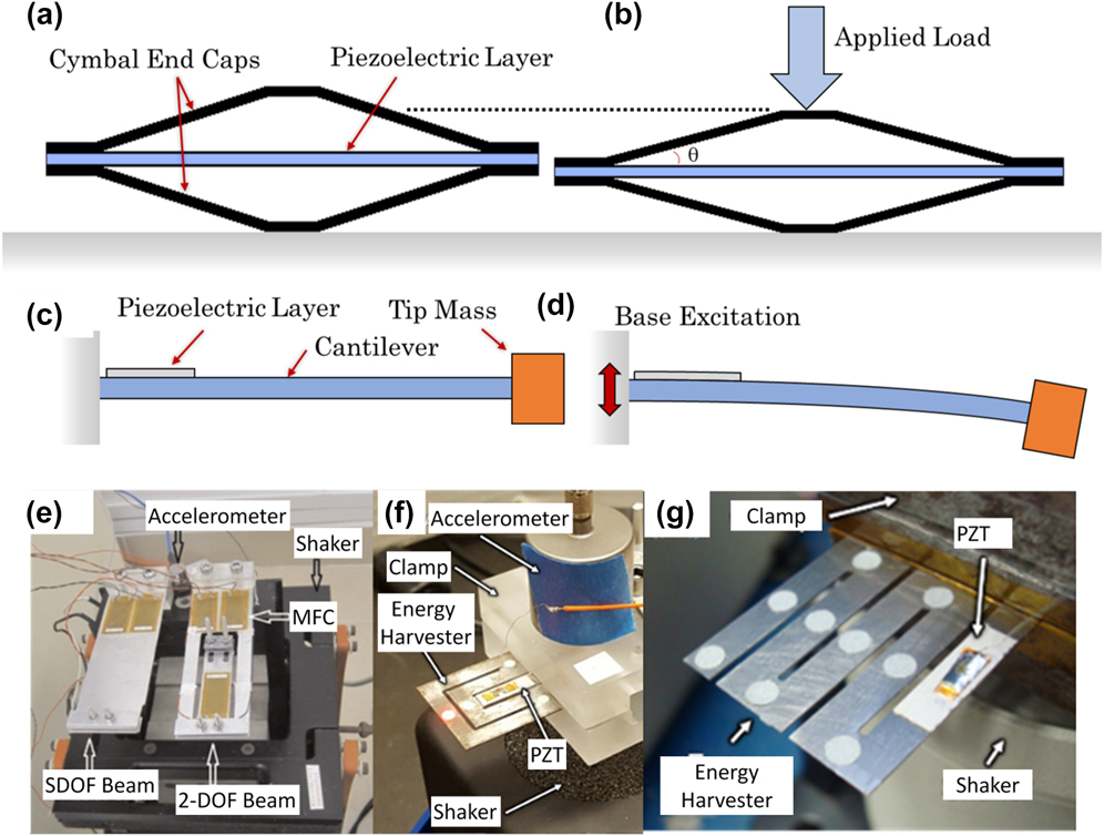
As mentioned above, piezoelectric materials can be utilized in harvesting energy from wasted vibrations in the environment. The vibrations in large civil structures can be divided into two categories: bulk (less than 2 Hz) and secondary (between 2 and 100 Hz). The low frequency bulk vibrations with higher force can be harvested using cymbal or stack transducers. Civil structures, like buildings, also have secondary vibrations with higher frequency (less than 100 Hz), which can be harvested using cantilever-type structures (zigzag, unimorph, and bimorph). These cantilever structures can also be used to harvest vibrations from transportation systems and household appliances, with vibration frequency less than 250 Hz. Furthermore, biomechanical movements can be harvested to power wearable and implantable biomedical devices.Reference Shi, Wang and Lee120,Reference Zhang, Gao, Wang, Liao, Qiu, Yang, Xue, Shi, Zhao, Xiong and Chen121 These harvesters are mostly flexible and can be classified as wearable (less than 3 Hz) and implantable (less than 20 Hz), depending upon their application. The flexible energy harvesters (FEHs) can be based on macro fiber composite, polyvinylidene difluoride (PVDF), nanogenerators, etc. The list of various vibration sources, frequency, and acceleration are given in Table II. As discussed earlier, depending upon the characteristics of the vibration platform, piezoelectric vibration energy harvesters can be modeled, fabricated, and integrated.
List of various vibration sources, frequency, and acceleration.

Similar to mechanical vibrations, magnetic fields are ubiquitously available and are an attractive source for energy harvesting.Reference Collin and Collin122 Stray magnetic fields are widely present as parasitic magnetic noise around power cables, electric home appliances, transportation systems, electromagnetic motors for manufacturing systems, industrial equipment, etc.Reference Ko, Park, Kim, Won, Chung and Kang115,Reference Zhou, Apo, Sanghadasa, Bichurin, Petrov, Priya, Srinivasan, Priya and Sun126 Magnetic fields in typical households vary between 0.01 and 10 Oe and may even exceed 100 Oe in industrial spaces with heavy electrical machinery.Reference Boughey, Kar-Narayan, Lanceros-Méndez and Martins127 The electrical energy harvested from magnetic fields can be used to power devices on-site in a variety of conditions, for example, wireless sensor nodes operating in residential, commercial, and industrial buildings, sensors deployed in remote or hazardous locations, and structural health monitoring sensors for monitoring the condition of industrial machinery, as shown in Fig. 1.Reference Boughey, Kar-Narayan, Lanceros-Méndez and Martins127–Reference Annapureddy, Lee, Yoon, Woo, Lee, Palneedi, Kim, Choi, Jeong, Yi and Ryu129
Traditional electromagnetic generators, based on Faraday’s law of induction, have been utilized to harvest energy from magnetic fields. However, magnetic energy harvesting via inductive coupling is often limited by issues related to size (it strongly affects energy density of the device), frequency, and efficiency of the electromagnetic generators. As an alternative, energy harvesting using magneto-mechano-electric (MME) generators has been proposed.Reference Dong, Zhai, Li, Viehland and Priya130 The MME generators are based on the cantilever-structured piezoelectric and magnetostrictive composite materials. These composites are designed to exploit the ME coupling effect and magnet as a permanent proof mass for inducing magnetic torque. During the operation, MME generators convert the magnetic field into flexural motion/strain via magnetic interaction between the proof mass and magnetic field and through magnetostriction of the ME composite. The resultant mechanical strain is converted into electrical energy via the piezoelectric component of the ME composite. By combining a wide variety of piezoelectric and magnetostrictive materials, efficient ME composites can be developed.Reference Boughey, Kar-Narayan, Lanceros-Méndez and Martins127 The utilization of MME generators has successfully been demonstrated in applications such as charging a mobile phone battery and a supercapacitor, driving a small DC motor fan, and lighting up of light emitting diodes (LEDs).Reference Ryu, Kang, Zhou, Choi, Yoon, Park, Choi, Hahn, Ahn, Kim, Kim, Priya, Lee, Jeong and Jeong103,Reference Annapureddy, Kim, Palneedi, Lee, Choi, Yoon, Park, Choi, Hahn, Ahn, Kim, Jeong and Ryu114,Reference Annapureddy, Lee, Yoon, Woo, Lee, Palneedi, Kim, Choi, Jeong, Yi and Ryu129
A. Dependence of generated output power on geometry
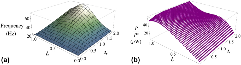
The most used configuration (resonant type) for harvesting energy from vibrations using piezoelectric principle is a unimorph cantilever. Modeling of piezoelectric cantilevers has been conducted by several researchers,Reference Hyunuk Kim, Priya, Priya and Inman10,Reference Sodano, Park and Inman131,Reference Erturk, Inman, Priya and Inman132 and it has been shown that the length and thickness of a given piezoelectric material relative to the substrate can affect the output power significantly. To determine the optimum length and thickness, two ratios are defined. The length ratio, l r, is defined as the ratio of piezoelectric material length to the substrate length, and thickness ratio, t r, is the ratio of piezoelectric material thickness to the substrate thickness. The power, P, developed by a unimorph topology can be described byReference Sriramdas133 P = (F 2/(Mωn))P*, where F, M, ωn, and P* are force, equivalent mass, frequency, and power factor, respectively. Hence, the power can be increased by increasing F and decreasing Mωn. The frequency, ωn, depends on the dimensions of the harvester as shown in Fig. 5(a). It can be observed that for each thickness ratio, there exists a maximum value for frequency depending on the value of length ratio. The nominal power, P/P*, depends on harvester dimensions and excitation force. For a given base excitation of 0.2 g n, F and M are evaluatedReference Sriramdas, Chiplunkar, Cuduvally and Pratap134 and the nominal power as a function of length ratio and thickness ratio is shown in Fig. 5(b). It can be observed that power developed by the harvester increases with length ratio. For smaller thickness ratios (t r < 1), there exists an optimum value of piezoelectric length ratio at which power is maximum. At higher values of thickness ratios, the nominal power has local minimum where frequency is higher and a global maximum at l r = 1. Hence, an optimum set of thickness and length of the piezoelectric material have to be selected to achieve optimal power from piezoelectric unimorphs.
(a) Effect of length ratio, l r, and thickness ratio, t r, on the natural frequency of a unimorph with a nominal substrate length of 107 mm and thickness of 300 µm. For a given thickness ratio, there exists an optimum length ratio at which the frequency is maximum. (b) Distribution of nominal power from a PZT unimorph as a function of l r and t r. For smaller values of thickness ratios, there exists an optimum length ratio at which the nominal power is maximum.Reference Sriramdas133

B. ME composites for magnetic energy harvesting
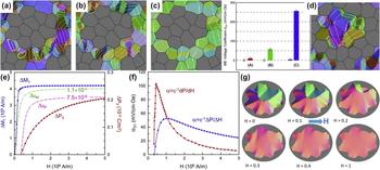
This section provides an overview on the theoretical understanding of the ME composites. The computational studies based on phase field modeling and simulation provide insights into the microstructure–property–mechanism relationships of ME composites.Reference Ma, Jin, Wang, Kampe and Dong135 The ME effect requires the piezoelectric effect of the ferroelectric phase, which must be electrically poled in situ within the composite structures to exhibit piezoelectricity.Reference Nan, Bichurin, Dong, Viehland and Srinivasan136,Reference Eerenstein, Mathur and Scott137 Poling serves to reorient the polarization of the electric domains in each grain toward one preferential direction (poling direction), thus rendering a macroscopic polar axis and piezoelectricity to the ferroelectric phase.Reference Ma, Jin, Wang, Kampe and Dong135 Using TbxDy1−xFe2 (Terfenol-D) and Pb(Zr1−xTix)O3 (PZT) as prototypical magnetostrictive and ferroelectric materials, the effects of phase connectivity and electrical conductivity of the magnetic phase on the in situ poling of the ferroelectric phase and the properties of this ME composite have been investigated,Reference Ma, Jin, Wang, Kampe and Dong135 as shown in Fig. 6. The simulated polarization distributions in continuous and isolated ferroelectric phases under different conditions are shown in Figs. 6(a)–6(d), with the corresponding ME voltage coefficient, α31, compared in the bar chart in Fig. 6.Reference Ma, Jin, Wang, Kampe and Dong135 The simulations show that 0–3 phase connectivity of magnetostrictive particles embedded in the continuous ferroelectric matrix is necessary to produce ME effect, while isolated ferroelectric particles embedded in the magnetostrictive matrix cannot be poled and thus the composite does not exhibit the ME effect. In the former case, the unpoled composite does not exhibit the ME effect, where the polarization vectors form numerous vortices, as shown in Fig. 6(a), and thus the ferroelectric phase does not possess macroscopic polarization, leading to the lack of the piezoelectric effect; on the other hand, the ME effect is observed in poled composites. In the latter case, if the magnetic matrix is electrically conductive, the electric field cannot be applied to the isolated ferroelectric particles; on the other hand, if the magnetic matrix is nonconductive, a strong depolarization field prevents poling of the isolated ferroelectric particles, as shown in Fig. 6(d). Interestingly, the simulations show that the finite (very small but nonzero) conductivity of the magnetic phase could be exploited to achieve better in situ poling of the ferroelectric phase and thus a higher ME voltage coefficient in the composite.
Effects of phase connectivity and electrical conductivity of the magnetic phase on the poling of the ferroelectric phase and the property of the ME composite (Reproduced with permissionReference Ma, Jin, Wang, Kampe and Dong135). Polarization distributions in the continuous ferroelectric phase under different conditions: (a) unpoled, (b) poled, and (c) poled with finite (small but nonzero) electrical conductivity of the magnetic phase. (d) ME voltage coefficients α31 under corresponding conditions are compared in the bar chart. For comparison, α31 of the particulate composite with the isolated ferroelectric phase is shown to the left of each corresponding case. The right side of (d) exhibits polarization distribution in the isolated ferroelectric phase after poling. (e)–(g) Simulated magnetization, polarization, and ME responses of the composite under externally applied magnetic field (Reproduced with permissionReference Ma, Jin, Wang, Kampe and Dong135). (e) Changes of magnetization, polarization, and magnetostrictive and electrostrictive strains as induced by magnetic field. (f) Effect of bias magnetic field on ME coefficient. (g) Simulated magnetic domain evolution in the magnetostrictive phase under horizontal magnetic field H (×106 A/m).

Nonmetallic magnetostrictive materials, such as ferrites, are nonconductive with large resistivity and their conductivity is very small but nonzero depending on material processing. Such a small but nonzero electrical conductivity of the magnetic phase produces a very weak effect over short time periods, such as when sensing AC signals, since free charges do not have sufficient time to redistribute due to the low conductivity. However, over long time periods, such as during DC electrical poling of the composites, the finite electrical conductivity of the magnetostrictive phase allows sufficient time for the free charges to redistribute through the magnetic phase, reducing the spatial charges accumulated at the interphase interfaces and thus the depolarization field in the ferroelectric phase. The simulated polarization distributions in the poled ferroelectric phases without and with electrical conductivity of the magnetic phase are compared in Figs. 6(b) and 6(c), which show more complete poling in the latter case, leading to higher α31, as shown in the bar chart. Therefore, if appropriately exploited, the small conductivity of the isolated magnetic phase in ME composites could produce a “beneficial” effect. However, conduction always leads to loss under AC fields so that it must be cautious to exploit this “beneficial” effect.
Similarly, the ME effect also requires the piezomagnetic effect of the magnetostrictive phase, which is usually achieved under a bias magnetic field. Without magnetic bias, the magnetic phase exhibits a magnetostrictive response with a vanishing piezomagnetic coefficient at zero field, leading to a vanishing ME effect in the composite. The effect of bias magnetic field on the ME response has been studied,Reference Ma, Jin, Wang, Kampe and Dong135 as shown in Figs. 6(e)–6(f). Figure 6(g) shows the simulated evolution of magnetic domains under horizontal magnetic field. The simulated dependence of α31 on magnetic bias shows that the ME effect is highly nonlinear and sensitive to external magnetic fields. Thus, achieving high ME voltage coefficient requires an appropriate choice of bias magnetic field. The simulated responses of magnetization, polarization, and magnetostrictive and electrostrictive strains, as induced by the magnetic field, reveal that the polarization response lags behind the magnetization response. This is a direct result of domain-level indirect coupling mediated through the heterogeneous strain field, where the ME coupling depends on the efficacy of transferring magnetostrictive strain into electrostrictive strain via elastic interaction between the two constituent phases. While the magnetostrictive strain and electrostrictive strain directly respond to the respective changes in magnetization and polarization, the magnetostrictive strain generated inside the polycrystalline magnetic particulates does not interact strongly with the surrounding ferroelectric matrix. Instead, it is the magnetostrictive strain generated near the interphase interfaces that is mostly responsible for the ME coupling, strongly interacting with the ferroelectric phase across the interface and causing polarization change near the interface, which suggests that plate-like phase morphology and layered architecture are most effective for strain-mediated ME coupling, thereby for magnetic energy harvesting.
IV. VIBRATION AND MAGNETIC FIELD ENERGY HARVESTERS USING LEAD-FREE MATERIALS
In this section, we review various materials and methods for harvesting stray vibrations and magnetic field using lead-free piezoelectric materials and composites.
A. Bulk vibration energy harvesters
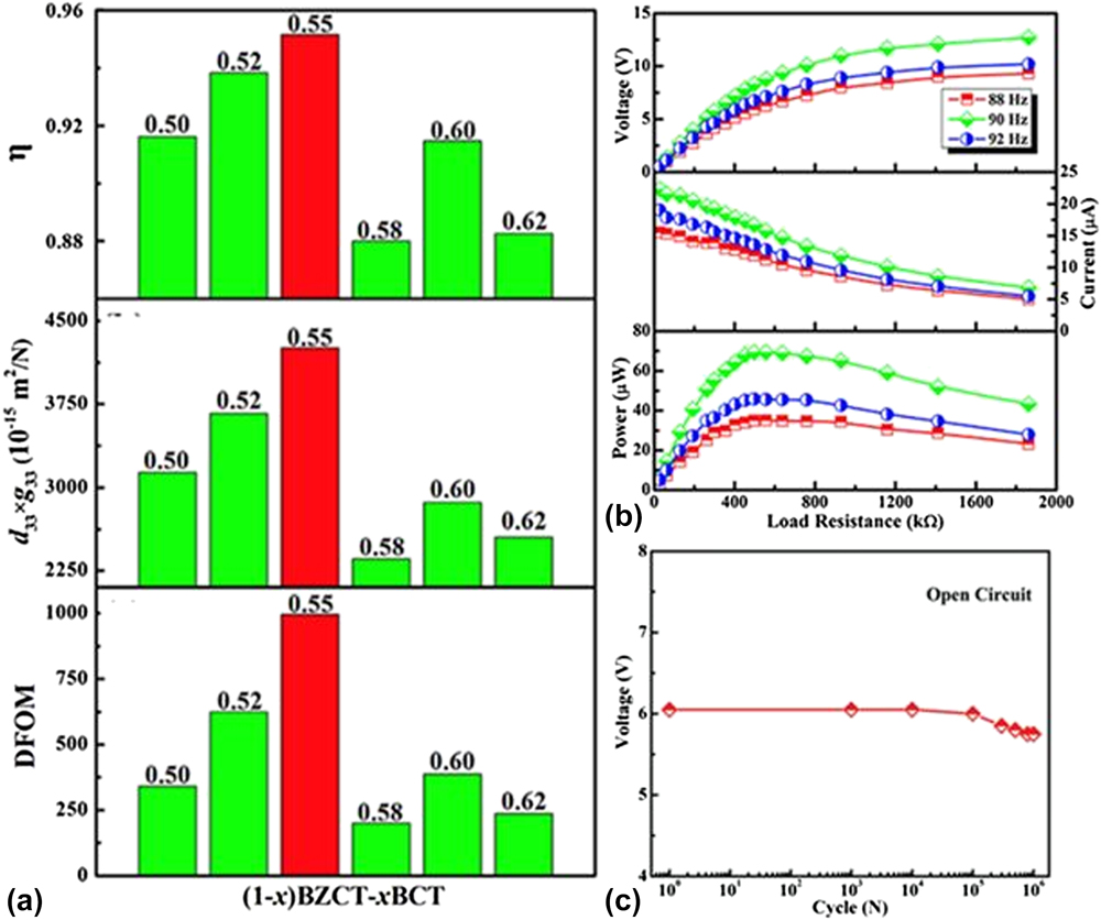
A novel lead-free material system (1–x)Ba(Zr0.1985Cu0.0015Ti0.8)O3–x(Ba0.7Ca0.3)TiO3 [(1–x)BZCT–xBCT] was fabricated by Yan et al.Reference Yan, Zheng, Hou and Zhu138 and characterized for piezoelectric properties and energy harvesting characteristics. With increasing value of x, the phase structure was changed from R phase to T phase through an R–O–T multiphase coexistence region. Excellent piezoelectric property and energy harvesting characteristics were obtained for the x = 0.55 specimen [Fig. 7(a)], where an R–O–T multiphase coexistence was found to play a crucial role in facilitating polarization rotation due to the low energy barrier. For the cantilever-type energy harvester, an output power of 70 μW and voltage of 8 V were obtained for x = 0.55 specimen at a low resonance frequency of 90 Hz and acceleration of 10 m/s2 with an impedance-matching resistance of 500 kΩ [Fig. 7(b)]. On increasing acceleration to 50 m/s2, the power output and voltage were further increased to 700 μW and 25 V, respectively.
(a) Energy conversion efficiency (η), transduction coefficient (d 33 × g 33), and the DFOM of the (1 − x)BZCT–xBCT ceramics. (b) Output voltage, output current, and output power as a function of load resistance for the x = 0.55 harvester at an acceleration of 10 m/s2. Reprinted with permission from Ref. Reference Yan, Zheng, Hou and Zhu138. (c) Fatigue cycle-dependent open circuit voltage of the 870 °C sintered 1.0 mol% Mn–KNN energy harvester at an acceleration of 10 m/s2 (Reprinted with permission from Ref. Reference Zheng, Hou, Yan, Zhang and Zhu139).

In energy harvesting applications, piezoelectric materials experience a large number of mechanical cycles, and, in some cases, shock stresses. This makes it important to study the mechanical behavior of piezoelectric ceramics, especially for the fracture toughness. Zheng reported a high quality 1.0 mol% Mn-modified (K0.5Na0.5)NbO3 (Mn–KNN) lead-free piezoelectric ceramic, prepared via sparking plasma sintering (SPS).Reference Zheng, Hou, Yan, Zhang and Zhu139 The 1.0 mol% Mn–KNN ceramics sintered at 870 °C were found to exhibit a highly dense (98.5% of relative density) and fine-grained structure. SPS has also been instrumental in avoiding loss of alkali ions during sintering, consequently reducing compositional fluctuation in the sintered specimen. The SPS-sintered 1.0 mol% Mn–KNN exhibited a high piezoelectric response and good mechanical properties. The energy conversion efficiency (η) and the dimensionless figure of merit (DFOM) values were found to be as high as 0.92 and 300, respectively. The samples sintered in the range of 840–900 °C exhibited both high H v and K IC values at the levels of 3.25–3.5 GPa and 1.8–1.95 MPa m1/2, respectively, which is significantly higher than the commonly used lead-based materials (K IC is usually near 1.0 MPa m1/2, such as 0.98 MPa m1/2 for 0.5PMN–0.3PZN–0.2PT and 1.25 MPa m1/2 for 0.2PZN–0.8PZT). In a cantilever-type energy harvester (resonant type), an output power of 85 μW and peak-to-peak voltage of 16 V were obtained at the acceleration of 40 m/s2. The energy harvester exhibited good fatigue resistance up to 106 cycles, as shown in Fig. 7(c). Akyurekli et al.Reference Akyurekli, Gurbuz, Gul, Gulec and Dogan140 have implemented a lead-free 94Na0.5Bi0.5TiO3–6BaZrxTi1−xO3; x = 0.1 (NBT–BZT) piezoelectric ceramic in bulk and cymbal forms (nonresonant-type architecture). They found that the energy harvesting efficiency of NBT–BZT in the cymbal form was better than that in the bulk form. The output voltage of NBT–BZT cymbal energy harvester was close to that of PZT4-based energy harvester.
B. MEMS vibration energy harvesters
Microelectromechanical systems (MEMSs) are a promising pathway toward realizing miniature piezoelectric energy harvester with high power density. Figures 8(a) and (b) show the general cantilever structure (resonant-type) of a MEMS piezoelectric energy harvester to produce large mechanical strain on the piezoelectric material under low vibration amplitude. Development of high quality piezoelectric thin film on silicon-, metal-, or ceramic-based substrates is the first stage for demonstrating the MEMS piezoelectric cantilever. Utilizing various deposition techniques, such as sputtering, sol–gel, pulsed laser deposition, and aerosol deposition (AD), micron thick piezoelectric films were deposited on the substrate, and next the cantilever structure and tip mass were manufactured through photolithography, etching, and lift-off techniques.Reference Le Van, Motoaki, Fumimasa, Kenji, Tomoyoshi and Hiroki141
(a) Schematic illustration of the typical cantilever structure for MEMS piezoelectric energy harvesting (Reprinted with permission from Ref. Reference Sriramdas and Pratap148). (b) MEMS energy harvester using the 0.5 mol% Mn-doped KNN thin film. (c) Peak voltage and the average power output of the energy harvester at the resonance frequency of 132 Hz as a function of load resistance (Reprinted with permission from Ref. Reference Won, Lee, Venugopal, Kim, Lee, Kim, Kingon and Kim145). (d) Representation of acceleration normalized power generated by a piezoelectric energy harvester (PEH). The product of five factors Scaling, Composition, Inertial, Material, and Power factors abbreviated by SCIMP factorsReference Sriramdas and Pratap148 represents the normalized power and thus increases with increasing each factor (Reprinted with permission from Ref. Reference Sriramdas and Pratap148).

Yoshimura et al.Reference Takeshi, Shuichi, Keisuke, Kento and Norifumi142 demonstrated a lead-free piezoelectric MEMS energy harvester using the BiFeO3 film. This micromachined harvester with a resonant frequency of ∼98 Hz exhibited an output voltage of 1.5 V/g and electrical power of 2.8 µW/(mm3 g2) across a load resistance of 1 MΩ. The estimated electromechanical coupling factor was found to be 0.41%. Kanno et al. fabricated a cantilever-type MEMS energy harvester with a lead-free (K0.5,Na0.5)NbO3 (KNN)-based piezoelectric material and compared its output performance with a PZT thin film-based energy harvester.Reference Kanno, Ichida, Adachi, Kotera, Shibata and Mishima143 Both the materials, PZT- and KNN-based, exhibited similar piezoelectric coefficients, e 31,f ∼ −11 C/m2. The average output power of KNN and PZT films reached 1.1 µW and 1.0 µW, respectively. The generalized electromechanical coupling factors for KNN/Si and PZT/Si cantilever harvesters were calculated to be 1.7 × 10⁻³ and 0.65 × 10⁻³, respectively.
A major challenge for demonstrating lead-free MEMS energy harvesters is synthesis of high quality lead-free thin film due to volatile elements and high temperature crystallization. High temperature processing causes thermal damage owing to large difference in the coefficient of thermal expansion between the substrate and thin film. To overcome structural instability in the lead-free piezoelectric thin film, compositionally modified lead-free piezoelectric materials have been developed by adding special dopants. Kim et al. reported that the highly dense lead-free (Na0.5,K0.5)(Nb0.95,Ta0.05)O3 (NKNT) thin film was obtained on a Si wafer by adding the BiFeO3 (BFO) dopant.Reference Kim, Leung, Koo, Kuhn, Jiang, Kim and Kingon144 Pure NKNT was found to exhibit a porous microstructure, whereas 5 mol% BFO doping improved the density of the film, leading to significantly reduced leakage current. Furthermore, the film exhibited a high effective piezoelectric coefficient (d 33,f) of ∼57 pm/V. A cantilever-type MEMS piezoelectric energy harvester fabricated with BFO-doped NKNT thin film generated a maximum power output and the corresponding peak voltage of 1.82 μW and 380 mV, respectively, at the resonance frequency of 130 Hz under 0.75 g acceleration amplitude. Won et al. studied 0.5 mol% Mn modified KNNReference Won, Lee, Venugopal, Kim, Lee, Kim, Kingon and Kim145 thin film that exhibited ∼104–105 times lower leakage current density compared to the pristine KNN film, due to the compensated free hall carriers resulting from multiple valance states of the Mn (+2, +3, or +4). The ferroelectric hysteresis curves of the pristine KNN film include a large contribution of the leakage current on the polarization measurement. By contrast, Mn-doped KNN showed a typical ferroelectric hysteresis loop. The low leakage current and high breakdown strength of the Mn-doped KNN film enabled a sufficient dipole alignment process (poling) without any electrical damage to the film, resulting in high piezoelectric coefficients (d 33,f ∼ 90 pm/V and e 31,f ∼ −8.5 C/m2). The fabricated MEMS cantilever generated an open circuit peak voltage of 520 mV at its resonance frequency of 132 Hz under 1 g input excitation. The output power was maximized at a matching load resistance of 9.6 kΩ. The maximum peak power and power density were found to be 3.62 W and 1.8 mW/cm3, respectively [Fig. 8(c)].
Achieving enhanced power output in MEMS energy harvesters is quite challenging. Vibration energy harvesters have been found to exhibit increased power output by having larger volume.Reference Marin146 Normalized power density also exhibits an increasing trend with increasing device volume. It is, therefore, quite challenging to achieve smaller devices with enhanced power output. However, the power output of an energy harvester not only depends on its volume but also on several other factors including properties of the active material, vibration amplitude, acceleration, etc. Therefore, to compare the performance of various energy harvesters, a dimensionless parameter-based morphology was proposed by Sharpes et al.Reference Sharpes, Abdelkefi and Priya147 The relative nondimensional harvester performance figure of merit can be given asReference Sharpes, Abdelkefi and Priya147
 $$S = {S_{\rm{P}}}{s_{\rm{P}}}{S_{\rm{M}}}{s_{\rm{M}}}{S_{{\rm{BW}}}}{s_{{\rm{BW}}}}{S_{\rm{V}}}{s_{\rm{V}}}\quad ,$$
where the uppercase letters indicate the relative dimensionless parameters and the lowercase letters are the weighing coefficients. The sum of the weighing coefficients equals unity. The individual dimensionless figures of merit can be given asReference Sharpes, Abdelkefi and Priya147
 $${S_{\rm{P}}} = {{{P_{{\rm{avg}}}}{W_{\rm{n}}}} \over {{M_{{\rm{eq}}}}{a^2}}},\;{S_{\rm{M}}} = {{\sqrt {s_{11}^E{\varepsilon ^T}} } \over {{d_{31}}}},\;{S_{{\rm{BW}}}} = {{{\Delta _{3{\rm{dB}}}}} \over {{\omega _n}}},\;{S_{\rm{V}}} = {{LW} \over {{T^2}}}\quad ,$$
where S P is the dimensionless power, S M is the dimensionless material, S BW is the dimensionless band width, S V is the dimensionless volume figure of merit,  $s_{11}^E$ is the compliance of the piezoelectric materials, εT is the permittivity of the materials, and Δ3dB is the half-power bandwidth of the average power versus frequency curve.Reference Sharpes, Abdelkefi and Priya147 The length, width, and thickness of a harvester are denoted as L, W, and T, respectively (including materials, tip masses, circuitry, etc.). The calculated parameter value for each harvester was divided by the maximum value of each parameter set to make each dimensionless parameter relative and normalized to unity. Furthermore, Sharpes et al.Reference Sharpes, Abdelkefi and Priya147 suggested that depending on the requirements, additional dimensionless parameters can be included and the weighting coefficients can be adjusted. The weighting coefficients are set per the goals of a given application. For example, if size constraints are critical in the design, the weighting coefficients of the dimensionless volume figure of merit can be made larger to give volume more influence over the final relative nondimensional harvester performance figure of merit.
Sriramdas et al.Reference Sriramdas and Pratap148 have also proposed a scaling method for high density vibration energy harvesting. A typical MEMS structure of a cantilever harvester is shown in Fig. 8(a). The power developed by a harvester increases rapidly with the size of the harvester, as discussed above. To determine the contribution of each element of the harvester, the expression for power, P, is normalized with square of the acceleration, a, such that the normalized power,  $\bar{P} = {P / {{a^2}}}$. The normalized power,
 $\bar{P}$, is shown as a product of five factors, abbreviated by SCIMP factors indicating scaling (Σp), composition (Γp), inertia (Ιp), material (Μp), and power factors (Π), as discussed in Ref. Reference Sriramdas and Pratap148. A portrait of the representation is shown in Fig. 8(d). The normalized power generated by the harvester is given by
 $$\bar{P} = {P \over {{a^2}}} = {\Sigma _{\rm{p}}}{\Gamma _{\rm{p}}}{{\rm I}_{\rm{p}}}{{\rm M}_{\rm{p}}}\Pi \quad .$$
As each factor explicitly consists of a set of particular parameters of the harvester, the power can be maximized by maximizing each factor separately. The scaling factor, Σp, is proportional to width of the beam and cube of the length. The composition factor, Γp, depends on a ratio of properties such as Young’s modulus (E), density (ρ), and thicknesses of the piezoelectric material and substrate material. The inertial factor, Ιp, is an explicit function of mass ratio, that is, the ratio of proof mass to the beam mass indicating the direct dependence of proof mass on the power generation. Similarly, the material factor, Μp, is defined as  ${{\rm M}_{\rm{p}}} = {\rho _{\rm{s}}}\sqrt {{{{\rho _{\rm{p}}}} / {{E_{\rm{p}}}}}}$, where subscript ‘p’ stands for the piezoelectric material and ‘s’ stands for the substrate. The power factor, Π, is maximum at the optimum load resistance and frequency. The maximum value of
 ${1 \over {16\zeta }}$ is expected to occur when the damping ratio, ζ, and coupling factor, k e, are related by
 $k_{\rm{e}}^ * = 2.258{\zeta ^{0.516}}$. For more details, reader is referred to Ref. Reference Sriramdas and Pratap148. However, the authors observed that the inertial and scaling factors are significant contributors to the power generation. Moreover, the material factor and power factor that directly depend on the material properties play a vital role in the power generation.
C. Nanogenerators
In this section, we review nanogenerators for harvesting vibration energy under off-resonance conditions. In the past few years, there have been increased efforts toward the fabrication/development of high performance piezoelectric energy harvesters in thin, soft, and flexible formats with significant power outputs for self-powered, bio-implantable, and medical applications. These energy harvesters generate electrical energy from small irregular vibrations and biomechanical movements. Many research groups have reported FEHs by fabricating piezoelectric nanostructures on flexible substrates, called as PNG. The use of piezoelectric nanostructures such as nanowires (NWs) and nanoparticles (NPs) for mechanical energy harvesting has advantages such as enhanced piezoelectric effect, superior mechanical properties, and high sensitivity to tiny forces.Reference Wang149 The predominant differences between nanogenerators and traditional piezoelectric energy harvester are as follows: (i) Generation of a large output power under off-resonance mechanical input, such as bending, folding, twisting, stretching, pressing, etc. Note that the output power is maximized at vibration resonance frequency in traditional piezoelectric energy harvesting. (ii) Utilizing flexible or nanomaterials, relatively large strain can be applied to the piezoelectric materials without device failure.
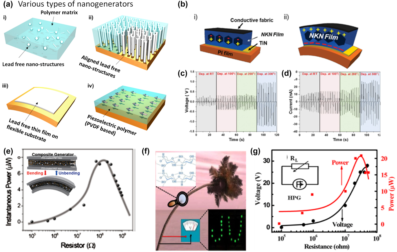
Prior studies have demonstrated that nanogenerators can be categorized into four different categories [Fig. 9(a)]: (i) Composite nanogenerators utilizing piezoelectric nanopowder mixed in a flexible polymer matrix. The composite is an effective route to enhance flexibility. However, the low volumetric contents of the piezoelectric materials in the composite tend to reduce the average piezoelectric performance of the devices. (ii) Exploiting aligned nanostructures where vertically induced stress on the piezoelectric materials can be concentrated. This result could be useful in producing high power output from the nanogenerator. However, the synthesis methods are very sensitive to processing conditions and it is hard to obtain reliable uniformity over a large scale. (iii) Flexible thin film in a desired form for the nanogenerator. Generally, piezoelectric ceramic thin films are synthesized at high temperature (>600 °C) for crystallization. Therefore, the conventional thin film process is incompatible with nanogenerators, which usually require flexible polymer substrates. To achieve integration of piezoelectric films onto flexible substrates, a special low temperature process and thin film transfer method has been developed. (iv) Piezoelectric polymers based on polyvinylidene fluoride (PVDF) have been used for nanogenerator applications, despite their relatively low piezoelectric properties, as compared to their ceramic counterparts.
(a) Schematics of various types of nanogenerators: (i) polymer matrix with lead-free nanostructures, (ii) aligned lead-free nanostructures, (iii) lead-free thin film on flexible substrate, and (iv) piezoelectric polymer (PVDF-based). (b) Schematic diagram of KNN thin film-based flexible nanogenerator (i) before and (ii) after bending. (c) Open-circuit output voltage and (d) short-circuit output current of the nanogenerator with KNN films grown at various temperatures (Reprinted with permission from Ref. Reference Kim, Lee, Hwang, Kim, Kim, Lee and Nahm151). (e) Output power under varied external resistance loadings in the range from 100 kΩ to 1 GΩ, with inset depicting illustration of the composite nanogenerator representing the bending and unbending states (Reprinted with permission from Ref. Reference Baek, Yun, Wang, Jeong, Lee, Park and Kim158). (f) Concept illustration of the cellulose-based composite nanogenerator. (g) Voltage and instantaneous power output from the cellulose-based composite nanogenrator as a function of the load resistance (Reprinted with permission from Ref. Reference Alam and Mandal166).

In an interesting study, Zhu et al.Reference Zhu, Yang, Wang and Wang150 demonstrated the fabrication of PNGs that involved the use of ZnO NWs on a flexible substrate for mechanical energy harvesting. Initially, the ZnO NWs were vertically grown on a Si substrate using the physical vapor deposition method. The vertically grown ZnO NWs were transferred on to a flexible substrate via the sweeping-printing method, which yielded an electrical output voltage of 2.03 V, current of 107 nA, and power density of 11 mW/cm3 under periodic stretching and releasing. The power generated by this PNG was enough to light up a commercial LED. Since then, there have been many attempts to transfer flexible piezoelectric materials from bulk substrates onto flexible substrates, to utilize their high inherent piezoelectric properties.
Since the generated energy density depends on the piezoelectric constant (d ij) of the piezoelectric material, higher d ij values found in perovskite-based piezoelectric materials are required for highly efficient FEHs. As discussed before, the high crystallization temperature (>600 °C) of perovskite-structured piezoelectric thin films has been a major challenge in achieving film-based energy harvesters. To overcome this limitation, Kim et al. synthesized a partially crystallized KNN thin film on a polyimide substrate at 300 °C.Reference Kim, Lee, Hwang, Kim, Kim, Lee and Nahm151 The KNN film contained 5 nm sized nanocrystallites in an amorphous phase. The nanogenerator based on this KNN film generated 2 V and 40 nA of output voltage and current, respectively [Figs. 9(b)–9(d)]. Using this technique, researchers demonstrated lead-free KNN-based ReRAM devices and memristors. Moreover, lead-free BT thin film (300 nm) based energy harvesters have been fabricated using RF magnetron sputtering and soft lithographic printing.Reference Park, Xu, Liu, Hwang, Kang, Wang and Lee152 The fabricated harvester was able to produce an output voltage of 1 V, current of 26 nA (current density of 0.19 μA/cm2), and peak power density of 7 mW/cm3 when it was bent by fingers. In another study, Jeong et al.Reference Jeong, Han, Palneedi, Park, Hwang, Joung, Kim, Shin, Kang, Ryu and Lee153 demonstrated the high output performance and bioimplantation of LiNbO3-doped (K,Na)NbO3 (KNN–LN) thin film-based FEHs using an AD process, followed by a laser lift-off technique. Initially, the KNN–LN film with the thickness of 2.7 μm was deposited onto a sapphire substrate and subsequently annealed at 800 °C for 1 h. The crystallized film was then transferred onto a flexible plastic substrate (125 μm thickness) by using a XeCl-pulsed excimer laser. The completed KNN–LN film was deposited on a flexible substrate with integrated electrodes. The average output voltage of 130 V and current of 1.3 μA under bending and 170 V and 5.5 μA under random flicking were achieved. Under bending, a maximum instantaneous power of ∼30 µW was obtained at ∼150 MΩ. This could be one of the best output performances among the lead-free piezoelectric KNN-based thin film FEHs.Reference Kim, Seo, Lee, Kim, Nahm, Kang, Yoon, Paik and Jeong154,Reference Gupta, Kim and Kumar155 Moreover, the KNN–LN FEH exhibited good short-time biocompatibility and converted the biomechanical energy from the heartbeat of a porcine into an electrical output of 5 V and 700 nA. Although this work established a lead-free FEH with high electrical energy output, it involved a complicated multistep process of transferring the films from the bulk substrate to flexible substrate.
Zhao et al.Reference Zhao, Liao, Zhang, Zhang, Liang, Liao and Zhang156 introduced a highly efficient flexible piezoelectric energy harvester using a composite of lead-free BaTiO3 particles (size ∼150 nm) and PVDF matrix on ITO-coated polyethylene terephthalate substrates using a facile and scalable solvent evaporation process. The uniform dispersion of BaTiO3 particles in the PVDF matrix helped us to enhance the piezopotential, strengthen the local stress, and induce larger deformation of the PVDF under the applied stress. As a result, the BaTiO3 particle-based (1 cm2 area) FEH produced a maximum open circuit of 150 V and short circuit current of 1.5 µA, under a stress of 10 MPa. The generated output was used for lighting three LEDs without any energy storage devices. Jeong et al.Reference Jeong, Park, Ryu, Hwang and Lee157 fabricated a flexible and large area (30 × 30 cm2) lead-free energy harvester by using a bar-coating method using KNN–LN particles and well dispersed copper (Cu) nanorods in a polydimethylsiloxane (PDMS) polymer matrix. Here, KNN–LN particles were used as power generation sources, with the Cu nanorods as energy enhancers. The fabricated large area FEH was able to produce an output voltage of 140 V, current of 8 μA, and power of 0.5 mW. Similarly, Na0.47K0.47Li0.06NbO3 microcubes in a PDMS matrix produced an output voltage of 48 V and current density of 0.43 μA/cm2 under the compressive force of 2 kgf with an energy conversion efficiency of 11%.Reference Gupta, Kim and Kumar155 Baek et al. reported a flexible composite nanogenerator with lead-free piezoelectric BZT–BCT NPs.Reference Baek, Yun, Wang, Jeong, Lee, Park and Kim158 The sandwich-structured nanogenerator composed of Ag NWs, BZT–BCT NPs, and a PDMS polymer template was fabricated to generate electricity under bending motion, as shown in Fig. 9(e). In an interesting effort, Jeong et al.Reference Jeong, Kim, Park, Oh, Paik, Hwang, No, Nam and Lee159 developed a unique method to synthesize lead-free nanomaterials using a virus template process. The virus-templated BaTiO3 nanocrystals were mixed with PDMS to fabricate a nanogenerator to achieve 6 V and ∼300 nA under bending motion. This harvester generated ∼15 V open-circuit voltage, 0.8 μA short-circuit current, and ∼8 μW power across 100 MΩ load resistance, which was enough to power and operate a commercial liquid crystal display (LCD) and LED.
Deutz et al. developed a highly sensitive lead-free composite nanogenerator for sensor applications.Reference Deutz, Mascarenhas, Schelen, de Leeuw, van der Zwaag and Groen160 At NKLN volume fraction of only 10%, the composite exhibited high piezoelectric coefficients (d 33: 17 pC/N and g 33: 220 10−3 Vm/N), which is comparable to PVDF-based piezoelectric polymers. The nanogenerator utilizing this composite generated a voltage of ∼20 V under an oscillating 15 N force. Joung et al. investigated the influence of the crystal structure of the KN NWs on energy harvesting performance.Reference Joung, Xu, Seo, Kim, Hur, Nahm, Kang, Yoon and Park161 KN NWs were synthesized with tetragonal, orthorhombic, and mixed tetragonal and orthorhombic phases (PPB). The composite nanogenerator containing PPB KN NWs exhibited the highest output among them. The maximum output voltage of 10.5 V and current of 1.3 μA were obtained under a strain of 2.1% and an average strain rate of 2.2%/s. Xu et al. synthesized PPB KNN nanorods with a piezoelectric response higher than that of KN.Reference Xu, Chakraborty, Remsing, Klein and Ren162 The NG containing PPB KNN nanorods exhibited a maximum open-circuit output voltage of ∼35 V, and a short-circuit current of ∼5.0 μA, under a strain of 2.13% and an average strain rate of ∼3.7%/s. These kinds of nanocomposites are mainly based on mixing NPs (piezoelectric and fillers) in a polymer matrix (may not be active like PVDF). The simplicity of the process could easily facilitate scaling of this process and cost-effectiveness.
In an attempt to use the advanced manufacturing process to fabricate nanogenerators, Gao et al.Reference Gao, Li, Li, Zhou and Song163 demonstrated the fabrication of a KNN NW-based FEH through the direct writing method. This method allows the simultaneous requirement of both a micropatterned structure, as well as aligned NWs, which helped to enhance the effective utilization of stress and strain. The direct written 1-layer KNN NWs FEH produced an output voltage of 21 V and current of 0.5 µA under periodic bending, which is an almost 400% enhancement, as compared to the spin-coated KNN NW flexible harvester (5.3 V). Furthermore, with increasing the number of printing layers, a maximum output voltage of 72 V was achieved. This research on direct writing piezoelectric NWs is quite important considering its advanced manufacturing technology.
Piezoelectricity also exists in natural materials, such as bones, hairs, collagen fibrils, peptide, cellulose, sugar cane, etc.Reference Lee, Zhang, Zueger, Chung, Yoo, Wang, Meyer, Ramesh and Lee164–Reference Fashandi, Abolhasani, Sandoghdar, Zohdi, Li and Naebe167 The natural piezoelectric materials have several advantages over the other classes of piezoelectric materials. For example, cellulose is a readily available polymeric raw material that exhibits a fascinating natural structure and is also treated as an eco-friendly and biocompatible product. In addition, cellulose is also utilized for versatile sensing applications and easily obtained from various plants as microfibrils, consisting of glucose–glucose linkages with linear chains. Alam et al. fabricated a composite nanogenerator based on native cellulose microfiber (NCMF) and MWCNTs [Fig. 9(f)].Reference Alam and Mandal166 Under repeated human hand punching, the NCMF-based nanogenerator showed an open circuit output voltage of ∼30 V and short circuit output current of ∼500 nA, corresponding to a power density ∼9.0 μW/cm3 [Fig. 9(g)], which was enough to power a number of LEDs, commercial LCD screen, calculator, and wrist watch.
Recently, successful growth of aligned lead-free piezoelectric nanostructures has been reported.Reference Koka, Zhou, Tang and Sodano168–Reference Fan, Jin, Wang, Hwang and Zhang171 He et al. reported [110]-oriented KNN nanorod arrays on the SrTiO3 (STO) substrate synthesized by a surfactant-free hydrothermal method.Reference He, Wang, Hu, Cai, Li, Gao, Zhang, Huang, Hu and Gu169 The piezoelectric constant, d 33, along the [110] orientation of the nanorods was found to be ∼140 pm/V. Using this array, a small nanogenerator was fabricated with PDMS filler and sandwiched electrodes. The nanogenerator produced impulsive voltage up to 10 and 4 V when the device was vertically pressed and bent. The generated power was found to be 2.25 nW under a load resistance of 10 MΩ. Tsege et al. demonstrated vertically aligned BTO nanotube arrays on a flexible Ti-mesh substrate. Uniformly grown BTO nanotube arrays were synthesized by anodizing the Ti mesh followed by a low temperature hydrothermal process. The nanogenerator was realized with a PDMS filler and sandwiched electrode. The resulting output voltage and current reached up to 10.6 V and 1.1 μA, respectively.Reference Tsege, Kim, Annapureddy, Kim, Kim and Hwang172
D. ME energy harvester
To harvest magnetic energy from magnetic sources present in the environment, there are two techniques reported in the literature: multimode piezoelectric-based magnetic-energy generators and multiferroic ME coupling-based MME generators. A piezoelectric cantilever with a permanent magnet tip mass has been utilized to design a multimode piezoelectric mangetic-energy generator. Liu et al.Reference Liu, Ci and Dong173 and Han et al.Reference Han, Hu, Wang, Wang and He174 designed piezoelectric cantilever structures with PZT and fiber-structured PZT and obtained a maximum output power density of 11.73 µW/cm3 at 100 Hz and 100 µT, and 421 µW/cm3 at 50 Hz and 2 mT, respectively. ME coupling is the result of multiple transductions, magnetic energy to mechanical energy to electrical energy. For these generators, the harvesting performance is commonly quantified by the ME coupling coefficient. Over the past decade, numerous ME composite materials have been evaluated for their use in magnetic-energy harvesting applications. Ryu et al.Reference Kambale Rahul, Kang, Yoon, Park, Choi, Ahn, Kim, Hahn, Jeong, Kim, Dong and Ryu175 demonstrated an MME generator with a simple ME structure (PZT ceramic fibers/Ni) that generated electricity from stray magnetic energy. This device generated a maximum power of 6 µW at 1 Hz. By changing the material combinations and device structure, high-performance magnetic-energy harvesters were demonstrated with output power varying from microwatt (µW) to milliwatt (mW) range.
Lasheras et al.Reference Lasheras, Gutierrez, Sousa, Silva, Martins, Lanceros-Mendez, Barandiaran, Shishkin and Potapov176 designed a flexible magnetic-energy harvesting device based on laminated ME composites using piezoelectric polymer materials. Piezoelectric PVDF polymer and magnetostrictive ribbons of metallic glass (Fe64Co17Si7B12) were utilized to prepare this energy harvester. Under an excitation of 45 µT magnetic energy, a 30 mm-long FEH generated an output power of 6.4 µW, which corresponds to a power density of 1.5 mW/cm3 across optimum load resistance and measured at the magnetomechanical resonance (46.8 kHz) of the structure. This output electrical power was high enough to be used in nanoelectronic systems. Unique ME responses of organic charge-transfer (CT) materials have been demonstrated because of exchange interaction induced by charge-spin coupling and delocalized π-electrons endowed organic CT complexes. Xu et al.Reference Xu, Chakraborty, Remsing, Klein and Ren162 fabricated a flexible magnetic-energy harvester using organic κ-(BEDT–TTF)2C60 [BEDT–TTF = bis(ethylenedithio)tetrathiafulvalene] CT (BCCT) crystals. This device was integrated with free-standing BCCT crystals and was brought into contact by two sets of electrodes for horizontal and vertical measurements. In another interesting work, a Helmholtz coil with an output AC magnetic field of 0.5 Hz was used for the magnetic-energy harvesting measurements using a flexible harvesting device. Under an excitation of 0.2 T, the horizontal energy harvester generated an output current of 62 pA and voltage of 67 µV, while an output current of 19 pA and voltage of 49 µV was generated by the vertically orientated BCCT energy harvester. An improved magnetic-energy harvesting performance was obtained for the device with horizontally orientated BCCT, as compared to that of the vertical orientated BCCT. This device provided an optimum power density of 4 × 10⁻¹² µW/(Oe2 cm3). The magnetic-energy conversion mechanism of BCCT-based energy harvesting devices is quite different from that of traditional ME oxides because it is a result of unique charge-spin-lattice coupling in molecular CT crystals.
V. GUIDANCE FOR THE IMPROVEMENT IN PERFORMANCE OF VIBRATION ENERGY HARVESTERS
This section reviews various device architectures and design-based strategies for improving the harvesting performance from stray vibrations and magnetic field.
A. Co-fired textured piezoelectric multilayer for energy harvesting
Under mechanical excitation, the piezoelectric materials generally give rise to a large voltage with low current. However, for rapidly charging an energy storage device (e.g., battery or supercapacitor), a larger current is required. Furthermore, piezoelectric materials have matching impedance on the order of ∼10 kΩ compared to ∼100 Ω for the energy storage devices. In a multilayer capacitor, the capacitance and output charge can be dramatically increased by manipulating the number of layers and materials propertiesReference Song, Kim, Kang, Kim, Yoon and Jeong177,Reference Roundy and Wright178 :
 $${C_n} = {\varepsilon _0}{\varepsilon _{\rm{r}}}{A \over {{t / n}}} \times n = {n^2} \times C\quad ,$$
 $${R_{\rm{m}}} = {1 \over {2\pi fC}} \cdot {{2\xi } \over {\sqrt {4{\xi ^2} + {k^4}} }}\quad ,$$
 $${V_{\rm{o}}} = E \cdot t = - g \cdot X \cdot t = - {{g \cdot F \cdot t} \over A}\quad ,$$
 $${R_{{\rm{m}},n}} = {1 \over {{n^2}}} \times {R_{\rm{m}}};\;{V_{{\rm{o}},n}} = {1 \over n} \times {V_{\rm{o}}};\;{I_n} = n \times I;\;{P_n} = P\quad ,$$
where C, R m, I, and V o are the capacitance, matching resistance, current, and open-circuit voltage of a single layer, respectively, C n, R m,n, I n, and V o,n are the capacitance, matching resistance, current, and open-circuit voltage of an n layer structure, respectively, f is the operating frequency, ξ and k are the damping ratio and piezoelectric coupling coefficient, respectively, while X is the stress applied on the piezoelectric materials.Reference Song, Kim, Kang, Kim, Yoon and Jeong177 Therefore, by fabricating a multilayer structure, one can achieve a reduced matching impedance, and smaller voltage, with higher current. To fabricate the multilayer piezoelectric ceramics, a cost-effective low-temperature co-fired ceramics process was utilized.Reference Gongora-Rubio, Espinoza-Vallejos, Sola-Laguna and Santiago-Avilés179
To harvest vibration energy using textured multilayer materials, a cantilever structure was fabricated. The resonant frequency of all the cantilevers was as low as 20 Hz.Reference Yan, Marin, Zhou and Priya180 The open circuit voltage of the single-layer textured sample (T-1) was twice that of the single layer random sample (R-1).Reference Yan, Marin, Zhou and Priya180 As discussed before, the generated voltage of a piezoelectric ceramic is determined by the piezoelectric voltage coefficient (g). The g for T-1 (14.7 × 10⁻³ Vm/N) was much higher than that of R-1 (9.6 × 10⁻³ Vm/N). For co-fired textured samples, single layer (T-1), bilayer (T-2), and trilayer (T-3), the generated voltage was found to decrease with an increase in number of layers.Reference Yan, Marin, Zhou and Priya180 The optimum resistive load was also found to decrease with an increase in the number of layers. The output power of all the samples as a function of acceleration was measured. Theoretically, the open-circuit voltage of a generator having n-layer should be n times smaller than that of a single-layer generator, if the layers are electrically connected in parallel. Moreover, the generator having n layers should exhibit n 2 times smaller optimum resistive load than that of a single-layer generator. The co-fired multilayer textured samples exhibited almost 6× higher output power than that of their randomly oriented counterpart. This result clearly suggests a high potential for the application of textured piezoelectric materials in vibration energy harvesting.
B. High energy density harvesting device architectures
Along with advances in piezoelectric material properties and fabrication methods, high energy density piezoelectric energy harvesters can be fabricated by optimizing the design of the mechanical amplifier, which imparts stress in the piezoelectric layer. Direct application of stress on a piezoelectric material is not often practical and rarely effective. Therefore, a mechanical amplifier is most often used. The mechanical amplifier is tailored to the energy harvesting source. Typically, energy sources are either thought of as high-force-low-frequency (HFLF)Reference Collin and Collin122,Reference Evans, Aw and Tang181 or low-force-high-frequency (LFHF),Reference Remick, Dane Quinn, Michael McFarland, Bergman and Vakakis182 and there are mechanical amplifiers advantageous for each.Reference Priya183 Low-force-low-frequency sources do not possess enough energy to make a worthwhile energy harvesting application, and high-force-high-frequency sources push the mechanical limits of engineering materials, making energy harvesting often inaccessible. An example of a HFLF mechanical amplifier is shown in Figs. 10(a) and 10(b) in a cymbal transducer. Cymbal transducers, like the one shown, amplify compressive vertical forces applied to the end caps (typically metal) and apply the amplified forces to the piezoelectric layer as tensile stress. This transducer has found applications in harvesting energy from human gait, a HFLF motion.Reference Sharpes, Vučković and Priya184,185 An example of a LFHF mechanical amplifier is shown in Figs. 10(c) and 10(d) in a cantilever beam transducer. Cantilever beam type transducers are attached to an energy source (base excitation) and utilize the inertia of a tip mass (at the free end) to bend the beam at resonance, stressing the piezoelectric layer near the fixed end. This transducer has been well studied and has found many applications and variations, such as vibrations from machinery and buildings.Reference Erturk and Inman186–Reference Zhu, Tudor and Beeby189
(a) Cymbal transducer suitable for HFLF. (b) Loaded cymbal transducer converting vertical compressive forces into horizontal tensile stress in the piezoelectric layer. (c) Cantilever transducer suitable for LFHF. (d) Bending response to base excitation (vibrations) shown with tensile stress in the piezoelectric layer. Both (b) and (d) utilize the piezoelectric in the 3-1 mode. (e) “Cutout cantilever” two-DOF design (Reprinted with permission from Ref. Reference Wu, Tang, Yang and Soh201), (f) “Elephant” type energy harvester (Reprinted with permission from Ref. Reference Sharpes, Abdelkefi and Priya147), and (g) “Zigzag” model 2D energy harvester. Reprinted with permission from N. Sharpes, A. Abdelkefi, and S. Priya: Comparative analysis of one-dimensional and two-dimensional cantilever piezoelectric energy harvesters. Energy Harvesting and Systems 5(3–4), 209–216 (2017), Fig. 2(b).

It has been shown that the energy density of cantilever-type energy harvesters can be increased by using a two-dimensional (2D) cantilever, rather than a one-dimensional (1D) design.Reference Sharpes, Abdelkefi and Priya190 2D cantilevers are those which spiral, curve, or meander in a plane and give more design freedom to tailor the dynamics of the mechanical amplifier beam to meet the energy source characteristics.Reference Apo, Sanghadasa and Priya191–Reference Wu, Tang, Yang and Soh201 To optimize the power output of these systems, it was shown that the structures should have an optimally pure bending motion (eliminate torsion) while concentrating stress in the piezoelectric layer, which increased power output over an order of magnitude compared to the previous state-of-the-art.Reference Sharpes, Abdelkefi and Priya147 The power output of a 2D cantilever can be increased by employing coupled modes.Reference Abdelmoula, Sharpes, Abdelkefi, Lee and Priya202 With particular 2D geometries, torsional motions can be made to yield a bending motion in the piezoelectric layer. The resulting increase in deflection can boost power output in application where vibration envelope is less of a concern. Several examples of 2D high energy density energy harvesters are given in Figs. 10(e)–10(g).
C. Boundary condition-based improvement
For vibrating systems, besides the physical structure of the system, the condition of the boundaries plays the greatest role in controlling the dynamics of the system. In general, more free boundaries yield lower frequency behavior and more fixed boundary conditions yield higher frequency behavior. This behavior arises because of the boundary condition’s effect on the stiffness of the vibrating system. Since most ambient vibration sources are relatively low frequency, one of the boundary conditions is almost a free condition.Reference Sharpes, Abdelkefi, Hajj, Heo, Cho and Priya203 Typically, the free end is considered to be the tip of the vibrating beam, where the tip mass is placed to alter resonant frequencies and amplitude of vibrations. The other end of the beam, the base, typically has some form of clamping or fixation. For vibrations occurring in one-dimensional translation, beams can have both translational and/or rotational degrees-of-freedom. Thus, for each degree-of-freedom (DOF), there can be various levels of clamping or freedom. Illustration of the three most common types of vibration boundary conditions are shown in Fig. 11(a).Reference Sharpes, Abdelkefi, Hajj, Heo, Cho and Priya203 Pendulums allow free rotation but do not allow for (or clamp) translation. Pendulums offer very low frequency performance due to the freedom at the boundary since the only restoring force is gravity. Clamped beams or cantilevers do not allow rotation or translation of the beam at the boundary. Cantilevers have relatively higher frequency performance due to the fixed boundary with the stress in the beam providing a restoring force. The hybrid between Pendulums and Clamped boundaries is the Freeplay boundary condition. In Freeplay, translation is free; however, rotation is fixed.Reference Sharpes, Abdelkefi, Hajj, Heo, Cho and Priya203 The vibration response due to such a boundary condition can be nonlinear and chaotic.
(a) Illustration of three most common types of vibration boundary conditions in Pendulum (free rotation, clamped translation), Clamped (clamped rotation, clamped translation), and Freeplay (clamped rotation, free but bounded translation). (b) Physical representation of the PEH, clamp, and shaker system, in which the clamp and shaker are held together by (c) a preloaded (tightened) screw with slightly mismatched threads allowing a larger than normal air gap between threads. When the excitation frequency is at the fundamental frequency of the clamp-screw system, (d) the response is enough to overcome the preload force and induce a second DOF, with one degree due to the stiffness of the PEH (k beam) and one due to the proposed preloaded freeplay (k screw). Power output as a function of frequency and electrical load resistance in the broadband interaction range for cantilever (e) and zigzag (f) systems, with the solid lines with filled points corresponding to the “normal” (clamped) boundary condition and the dashed lines with nonfilled points corresponding to the “spring” (preloaded freeplay) boundary condition. Effect of clamp mass (g) and screw tightness (h) on frequency and amplitude of preloaded freeplay effect with qualitative illustrations (i) and (j) depicting the effects shown in (g) and (h), respectively, and when one DOF or two are present (Reprinted with permission from Ref. Reference Sharpes, Abdelkefi, Hajj, Heo, Cho and Priya203).

Pendulums do not lend themselves well to piezoelectric energy harvesting since the beam is not stressed. Indeed, since rotation is free, there is nothing to cause bending stresses in the piezoelectric layer. Rather, they find application in electromagnetic harvesters, not discussed here. Due to this reality, clamped cantilevers are nearly exclusively used in piezoelectric vibration energy harvesting applications. Freeplay boundaries can allow some relative motion between the beam and vibration source.Reference Sharpes, Abdelkefi, Hajj, Heo, Cho and Priya203 When the beam translates against the bounds of the Freeplay, an amplified bending occurs since the base of the beam has an initial velocity condition. This dynamics can aid in energy harvesting and harvester bandwidth but is inherently chaotic. Combining the Clamped and Freeplay boundary conditions into the so-named “preloaded freeplay” boundary condition has been shown to significantly increase the harvester bandwidth without creating chaotic vibration behavior.Reference Sharpes, Abdelkefi, Hajj, Heo, Cho and Priya203 The preloaded freeplay effect is summarized in Figs. 11(b)–11(j). As shown in Figs. 11(e) and 11(f), the preloaded freeplay effect does not increase the amplitude of harvested power outright, rather spreads the spectral energy density out over a larger bandwidth, which is beneficial for vibration sources of nonconstant oscillation frequency.
D. Performance assessment of piezoelectric harvesters
Several efforts have been made to enhance the power generated by bimorph harvesters. Optimal beam shapes have been studied for improving the power.Reference Frank and Peter204–Reference Benasciutti, Moro, Zelenika and Brusa206 In addition to the shape of the harvester, proof mass, quality factor, and coupling factor influence the generated power.Reference Roundy207 The generated power from bimorph was compared with a triple layer harvester for a given thickness of the piezoelectric beam.Reference Zhu, Almusallam, Beeby, Tudor and Harris208 A recent study indicates that multistep harvesters can produce almost 90% higher power compared with a multilayer harvester constructed from the same volume of piezoelectric material.Reference Sriramdas, Chiplunkar, Cuduvally and Pratap134 A multistep harvester consists of the geometry shown in Fig. 12(b). The poling direction in adjacent layers is opposite, as shown in Fig. 12(c), such that all layers can be combined in parallel. An experimental result comparing two harvesters made of the same volume of PVDF is shown in Fig. 12(d). If the operating damping ratio of the harvester is small, say below 0.01, as per the distribution shown in Figs. 12(e) and 12(a), the coupling factor above 0.2 has no significant contribution to the power. There is an upper limit on the coupling factor for a given damping ratio at which the power is maximum. Hence, energy harvesters that have weak coupling can improve the power by employing methods that decrease damping ratio such as operating in a vacuum. Moreover, increasing the coupling factor increases the power, particularly, at high damping ratio. Coupling factor can be increased by selecting a material that has higher values of piezoelectric coupling constants.
Perspective view of (a) multilayer and (b) multistep harvesters showing a total of six layers on top and bottom of the beam. The volume of the piezoelectric material used in both beams is equal. Multistep harvesters have steadily decreasing cross section along the beam. (c) Cross section of the beam showing the poling direction in each layer. (d) Comparison of the power developed by multilayer and multistep harvesters. The power developed by multistep harvester is almost 90% more than that developed by a multilayer harvester constructed by the same volume of the piezoelectric material. (e) Contour plot of normalized power from a harvester at resonance and optimum load resistance. The power increases with the decreasing damping ratio and increasing coupling factor. However, for a given damping ratio, there is an upper limit on the achievable power and increase in the power factor has marginal contribution to the power beyond that coupling factor. (Reprinted with permission from Ref. Reference Sriramdas, Chiplunkar, Cuduvally and Pratap134)

E. Guidance for the improvement in the efficiency of ME energy harvester
Since the performance of the magnetic field energy harvester or MME harvester mainly depends on the coupling between the magnetostrictive and piezoelectric materials, it is required to use high permeability magnetostrictive materials with good mechanical quality factor and piezoelectric materials with larger piezoelectric coefficient and low loss.Reference Lasheras, Gutierrez, Sousa, Silva, Martins, Lanceros-Mendez, Barandiaran, Shishkin and Potapov176,Reference Lanceros-Mendez, Silva, Castro, Correia, Rocha, Martins, Lasheras and Gutierrez209 It is expected that by using textured/single crystal forms of both piezoelectric and magnetostrictive materials, the output power of MME designs can be significantly improved. Usually, MME harvesters generate electrical energy using mechanical vibrations induced by an AC magnetic field. Since the amplitude of the induced mechanical vibration is proportional to the intensity of the surrounding magnetic field, the magnetic field distribution inside ME composites influences the deformation and the resultant power output of the harvester. However, finite element analysis on high permeability Metglas sheets revealed that the magnetic field inside the material is more concentrated than in free space, which is called the magnetic flux concentration effect. Using this effect provided by the high permeability magnetic material, it is possible to enhance the ME coupling coefficient, as well as energy density of the MME topology, even in small magnetic fields.
VI. SUMMARY
Due to environmental and regulatory concerns, there has been focus on developing efficient lead-free piezoelectric materials, which can match the robust material properties of their lead-based counterparts. NBT- and KNN-based compositions have emerged as a potential candidate as the replacement for PZT-based materials. Various strategies based on compositional modification have been attempted for achieving the desired performance in piezoelectric materials. However, this approach has not been very successful in lead-free materials, unlike lead-based systems, due to reduced temperature stability, limiting their operational temperature range for practical applications. Solid-state single crystal growth (SSCG) has been found to provide high-performance cost-effective piezoelectric materials. Using texturing processes, single crystal-like properties can be achieved in polycrystalline ceramics without modifying composition. Also, textured materials are mechanically robust in comparison to their single crystal counterparts. The fabrication of multilayer-textured piezoelectric harvesters can dramatically increase the current, which could further reduce the charging time of an energy storage device. Different kinds of stray vibrations (with varying frequency and amplitude) and magnetic energy exist in nature, which can be efficiently harvested by carefully designing the structure of a harvester. A summary of various sources of vibrations and magnetic energy along with the corresponding structures for the energy harvesters was provided. An overview of different types of vibration energy harvesters (bulk, MEMSs, and nanogenerators) and magnetic energy harvesters, fabricated using lead-free piezoelectric materials and composites was provided.
ACKNOWLEDGMENTS
D.M. would like to acknowledge the financial support from Office of Basic Energy Science, Department of Energy, through grant number DE-FG02-06ER46290. H-C.S. and S.P. would like to acknowledge NSF-CREST Grant No. HRD 1547771. M-G.K. was supported through the Air Force Office of Scientific Research (Grant No. FA9550-14-1-0376). N.S. was supported through Office of Naval Research. R.S. and Y.Y. would like to acknowledge financial support through National Science Foundation I/UCRC program. H.-C.S. was supported by the National Research Council of Science & Technology (NST) grant by the Korea government (MSIP) (No. CAP-17-04-KRISS). KIMS and YU teams would like to acknowledge the support from National Research Foundation of Korea (Grant No. NRF-2016R1A2B4011663), the National Research Council of Science & Technology (NST) grant by the Korea government (MSIP) (No. CAP-17-04-KRISS), and the U.S. Office of Naval Research Global (Grant No. N62909-16-1-2135).