1 Introduction
Droplet collisions and impacts are iconic multiphase flow problems: rain, atomization of liquid jets, ink-jet printing and stalagmite growth all involve impact in one manner or another (Rein Reference Rein1993; Yarin Reference Yarin2006; Josserand & Thoroddsen Reference Josserand and Thoroddsen2016). The droplet may impact on a dry surface, a thin liquid film or a deep liquid bath. In all cases, impact may lead to the spreading of the droplet or to a splash whereby a myriad of smaller droplets are ejected far away from the zone of impact (Rioboo, Marengo & Tropea Reference Rioboo, Marengo and Tropea2001). Control of the outcome of impact is crucial for applications: for instance, spreading is desirable for coating or ink-jet printing while splashing may improve the efficiency of evaporation and mixing in combustion chambers. Two distinct types of splash, ‘prompt’ and ‘ordinary’, are now usually distinguished. The prompt splash is defined as a very early ejection of liquid at a time
 $t\ll D/U_{0}$
where
 $D$
is the droplet diameter and
 $U_{0}$
its velocity. A very thin liquid jet is formed, called the ejecta sheet (Thoroddsen Reference Thoroddsen2002), projected at high velocity, initially almost horizontally, and it is expected to disintegrate eventually into very small and rapid droplets. The second type of splash, often called also the corolla or crown splash, occurs at later times, through the formation of a vertical corolla ending in a circular rim that destabilizes into fingers and droplets (Deegan, Brunet & Eggers Reference Deegan, Brunet and Eggers2008; Agbaglah et al.
Reference Agbaglah, Thoraval, Thoroddsen, Zhang, Fezzaa and Deegan2015).
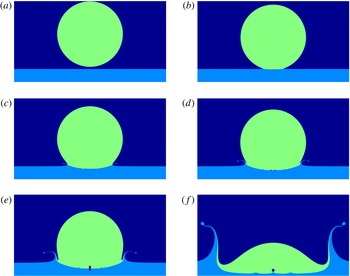
Very often, these two mechanisms are not easy to distinguish clearly since they happen in a sequence, the ejecta sheet being a precursor of the corolla, as illustrated by the numerical simulations of a droplet impact on a thin liquid film, shown in figure 1.
Snapshots of a droplet impacting on a thin liquid film for the parameters in tables 1 and 2, i.e.
 $\mathit{We}=500$
,
 $\mathit{Re}=2000$
and
 $\mathit{St}=2.26\times 10^{-6}$
, so that the jet number is
 $J=0.041$
. For the sake of visualization, the liquid of the droplet and of the layer have been coloured green and blue respectively, although it is the same liquid. The gas phase is coloured dark blue. The snapshots correspond to the dimensionless times
 $U_{0}t/D=-0.033$
,
 $0.0167$
,
 $0.083$
,
 $0.133$
,
 $0.217$
and
 $0.767$
respectively.

The dynamics of droplet impact is complex, involving singular surface deformation and pressure values in the inviscid limit and several instabilities of surface evolution, so that an overall understanding of the whole process is still lacking. In particular, the splash depends on many physical parameters, the most important being the impact velocity. Obviously, high velocities promote the splash while at low velocities the droplet gently spreads. More precisely, the splashing–spreading transition depends mostly on the balance, in the liquid, between inertial and viscous forces (Stow & Hadfield Reference Stow and Hadfield1981; Mundo, Sommerfeld & Tropea Reference Mundo, Sommerfeld and Tropea1995; Yarin & Weiss Reference Yarin and Weiss1995; Josserand & Zaleski Reference Josserand and Zaleski2003), characterized by the Reynolds and Weber numbers defined below. Although droplet impact on a solid surface or on a liquid film shows similar outputs, the physical mechanisms leading to these effects often have different origins. For droplet impact on solids, the surface properties play an important role, through its roughness and the contact line dynamics for instance. There, a remarkable discovery has been made recently: the surrounding gas (usually air) also plays a crucial role in splash formation (Xu, Zhang & Nagel Reference Xu, Zhang and Nagel2005), and understanding in detail the influence of the gas remains a challenge (Mandre & Brenner Reference Mandre and Brenner2012; Klaseboer, Manica & Chan Reference Klaseboer, Manica and Chan2014; Riboux & Gordillo Reference Riboux and Gordillo2014). In particular, the formation of a thin air layer at the instant of impact smooths the singularity expected in the absence of any gas and thus ‘cushions’ the impact, leading to the entrapment of an air bubble (Mehdi-Nejad, Mostaghimi & Chandra Reference Mehdi-Nejad, Mostaghimi and Chandra2003; Thoroddsen, Etoh & Takehara Reference Thoroddsen, Etoh and Takehara2003; Thoroddsen et al. Reference Thoroddsen, Etoh, Takehara, Ootsuka and Hatsuki2005; Mandre, Mani & Brenner Reference Mandre, Mani and Brenner2009; Duchemin & Josserand Reference Duchemin and Josserand2011). For drop impact on a liquid, the thickness of the liquid film is crucial and the corolla splash can be seen as the result of the collision between the spreading drop and the liquid layer at rest (Yarin & Weiss Reference Yarin and Weiss1995). There also, as has been noted experimentally and numerically, air bubbles are entrapped by the impact dynamics (Thoroddsen et al. Reference Thoroddsen, Etoh and Takehara2003; Thoraval et al. Reference Thoraval, Takehara, Etoh, Popinet, Ray, Josserand, Zaleski and Thoroddsen2012), although the effect of the surrounding air has been shown not to be as dramatic as on solid surfaces. However, a systematic study of its influence on the impact outputs is still lacking and a potential interplay between the bubble entrapment and the ejecta sheet still needs to be elucidated. In 2003, two of us (Josserand & Zaleski Reference Josserand and Zaleski2003, which we hereafter refer to as JZ03) proposed that the splashing–spreading transition observed in experiments and in numerics was controlled by the capillary–inertia balance within the ejecta sheet. The thickness in this theory was selected by a viscous boundary layer. In such a model, scaling laws for the jet thickness and velocity were deduced, neglecting the gas dynamics, and the existence of an entrapped bubble was not considered.
The goal of this paper is therefore to determine the properties of the ejecta sheet for the splashing of a drop on a thin liquid film, with a particular emphasis on the interaction between the jet formation and the gas dynamics. High-resolution numerical simulations of axisymmetric incompressible Newtonian two-phase flow will be used in order to exhibit the relevant physical mechanisms at the heart of the prompt splash in this framework.
2 The general problem
2.1 Geometry and dimensional analysis
We consider a droplet of diameter
 $D$
impacting on a thin liquid film of thickness
 $e$
with a velocity
 $U_{0}$
normal to the film interface. The liquid and gas have densities
 $\unicode[STIX]{x1D70C}_{l}$
and
 $\unicode[STIX]{x1D70C}_{g}$
and dynamical viscosities
 $\unicode[STIX]{x1D707}_{l}$
and
 $\unicode[STIX]{x1D707}_{g}$
respectively. The surface tension is
 $\unicode[STIX]{x1D70E}$
. In experiments the droplet impact is typically produced by the release of a drop at some height
 $H$
above the film, falling under gravity
 $g$
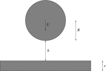
. In our case, the simulation starts with a small initial air gap
 $h_{0}$
between the film and the droplet and a velocity
 $U_{0}$
, as shown in figure 2. The droplet is assumed to be spherical. In order for this assumption to be valid we need (i) to have as little effect of the air flow on the droplet shape as possible, which should be verified if the gas Weber number
 $\mathit{We}_{g}=\unicode[STIX]{x1D70C}_{g}U_{0}^{2}D/\unicode[STIX]{x1D70E}$
is small or in a viscous regime, and (ii) to assume that the oscillations of the droplet shape caused by the droplet release mechanism (Wang, Kuan & Tsai Reference Wang, Kuan and Tsai2013) are as small as possible. The Froude number
 $\mathit{Fr}=U_{0}^{2}/(gD)$
that quantifies the influence of gravity during the impact is taken as constant and high (
 $\mathit{Fr}=800$
) for all the simulations, indicating that gravity has only a small effect on the dynamics. We will restrict this study to large liquid Weber numbers
 $\mathit{We}=\unicode[STIX]{x1D70C}_{l}U_{0}^{2}D/\unicode[STIX]{x1D70E}$
.
Sketch of the numerical simulation. A spherical droplet of radius
 $R$
and velocity
 $U_{0}$
is considered at a distance
 $h_{0}$
from a liquid film of thickness
 $e$
.

The problem is then mostly characterized by the dimensionless numbers
 $$\begin{eqnarray}\mathit{Re}=\frac{\unicode[STIX]{x1D70C}_{l}U_{0}D}{\unicode[STIX]{x1D707}_{l}},\quad \mathit{St}=\frac{\unicode[STIX]{x1D707}_{g}}{\unicode[STIX]{x1D70C}_{l}U_{0}D}\quad \text{and}\quad \unicode[STIX]{x1D6FC}=\frac{\unicode[STIX]{x1D70C}_{g}}{\unicode[STIX]{x1D70C}_{l}},\end{eqnarray}$$
which are the liquid Reynolds and Stokes numbers of the impact and the density ratio. These numbers compare the droplet inertia with viscous effects in the liquid and gas, respectively, and compare the liquid to the gas inertia. We note that
 $\unicode[STIX]{x1D70C}_{l}/\unicode[STIX]{x1D70C}_{g}$
has to be very large if one wants simultaneously to have
 $\mathit{We}_{g}\ll 1$
and
 $\mathit{We}\gg 1$
. An additional dimensionless number is the aspect ratio between the liquid film and the droplet,
 $e/D$
, which we keep relatively small and constant in this study. We expect the initial gas layer aspect ratio
 $h_{0}/D$
to be irrelevant if the conditions described above (
 $\mathit{Fr}\gg 1,\mathit{We}_{g}<1$
) are satisfied and
 $h_{0}$
is larger than the characteristic thickness
 $h_{b}$
defined below. Compressibility effects are characterized by the Mach numbers
 $\mathit{Ma}=U/a_{l,g}$
, where
 $a_{l}$
(respectively
 $a_{g}$
) is the speed of sound in the liquid (respectively gas), and in all our simulations these Mach numbers remain small enough so that compressibility effects can be neglected (Lesser & Field Reference Lesser and Field1983).
We note that the axisymmetric flow assumption is not valid when digitations and splash droplets form. However, at short times, before these instabilities can develop and particularly before the jet is created, we can consider this assumption correct (Agbaglah & Deegan Reference Agbaglah and Deegan2014). Otherwise the general three-dimensional (3-D) problem remains a grand numerical challenge because of the large range of scales involved (Gueyffier & Zaleski Reference Gueyffier and Zaleski1998; Rieber & Frohn Reference Rieber and Frohn1998). Despite some recent numerical results (Fuster et al. Reference Fuster, Agbaglah, Josserand, Popinet and Zaleski2009), realistic 3-D numerical simulations of droplet impact at short times are as yet hard to attain. Moreover, a solid basis for the analysis of the scaling of 3-D flow may only be attained when the scaling of 2-D flow has been uncovered. We thus postpone a detailed 3-D study of droplet impact for future work.
2.2 Scaling analysis
We analyse now the different mechanisms at play during droplet impact using simple scaling arguments. Recall that surface tension and gravity can be neglected, and in a first step, we will consider also that the surrounding gas has negligible effects. We then quite naturally define
 $t=0$
as the time at which the undeformed, spherical droplet at uniform velocity would touch the undeformed, planar liquid surface. With this definition of time, the initial time is
 $t_{0}=-h_{0}/U_{0}.$
We will now use an important geometrical argument first suggested by Wagner (Reference Wagner1932): considering the intersection of the falling sphere with the impacted film, it is straightforward to define the vertical length scale as
 $\ell _{z}=U_{0}t$
and the horizontal one as
 $r_{g}=\sqrt{D\ell _{z}}=\sqrt{DU_{0}t}$
. These apparently simple scalings arising purely from geometry are in fact very robust and relevant to the description of impact at short times: for instance, it has been shown that
 $r_{g}(t)$
gives a correct estimate of the so-called spreading radius, defined as the radius where the pressure is maximal (JZ03). Remarkably, the geometrical velocity of this intersection,
 $$\begin{eqnarray}v_{g}(t)=\frac{\text{d}r_{g}}{\text{d}t}=\frac{1}{2}\sqrt{\frac{DU_{0}}{t}},\end{eqnarray}$$
diverges at
 $t=0$
, questioning the incompressible assumption. However, although formally such a geometrical velocity diverges, fluid velocities remain much smaller and compressibility can be safely neglected for small Mach numbers. To make the article self-contained, we will now recall briefly the results obtained by JZ03. The key point is the numerical observation that the pressure field and the velocity field are perturbed over the length scale
 $r_{g}(t)$
so that a kind of inner–outer asymptotic analysis can be performed, in which the flow is uniform at scales larger than
 $r_{g}$
, potential at scales of order
 $r_{g}$
and viscous at scales much smaller than
 $r_{g}$
(a more rigorous asymptotic analysis was developed later in Howison et al. (Reference Howison, Ockendon, Oliver, Purvis and Smith2005)). In this analysis the ejecta speed is obtained using a mass conservation argument between the impacting droplet and the ejected sheet, assuming that the thickness of the jet is selected by a viscous length. More precisely, one can compute in this framework first the mass flux
 $F_{m}$
from the falling undeformed sphere through the undeformed film surface,
 $$\begin{eqnarray}F_{m}(t)\sim \unicode[STIX]{x1D70C}_{l}\unicode[STIX]{x03C0}r_{g}^{2}U_{0}.\end{eqnarray}$$
This flux can be absorbed either by surface deformation of the droplet and of the film or by the formation of an ejecta sheet. In JZ03, we have assumed that the thickness of such a sheet or jet is given by a viscous boundary layer formed at the base of the jet, leading to a viscous length scale
 $$\begin{eqnarray}e_{j}(t)\sim \sqrt{\frac{\unicode[STIX]{x1D707}_{l}t}{\unicode[STIX]{x1D70C}_{l}}}.\end{eqnarray}$$
Then, conservation of the volume flux through this jet implies that the jet velocity
 $U_{j}$
has to satisfy
 $$\begin{eqnarray}U_{j}\sim \sqrt{Re}U_{0}.\end{eqnarray}$$
Remarkably, this gives a nonlinear relationship between the jet and the impacting droplet velocity since then
 $U_{j}\propto U_{0}^{3/2}$
. Such a law has obviously some physical restrictions: first of all, the flux formula (2.3) is valid only for
 $t\ll R/(2U_{0})$
since our whole analysis is for short times and makes no sense for times of order
 $D/U_{0}$
. Furthermore, the jet velocity has to be larger than the geometrical velocity
 $v_{g}$
. Indeed, if
 $U_{j}<v_{g}(t)$
one would expect the ejecta sheet to be overrun by the falling droplet. This condition together with (2.2) yields a ‘geometric’ limiting time
 $t_{g}$
:
 $$\begin{eqnarray}t>t_{g}\sim \frac{1}{\mathit{Re}}\frac{D}{U_{0}}.\end{eqnarray}$$
When the ejecta forms, a bulge or rim appears at its tip according to the mechanism of Taylor (Reference Taylor1959) and Culick (Reference Culick1960). This rim moves backwards at the Taylor–Culick velocity
 $$\begin{eqnarray}v_{TC}=\sqrt{\frac{2\unicode[STIX]{x1D70E}}{\unicode[STIX]{x1D70C}_{l}e_{j}}},\end{eqnarray}$$
where
 $e_{j}$
is the thickness of the ejecta sheet. The ejecta sheet cannot form if its velocity is smaller than the Taylor–Culick velocity constructed with the thickness
 $e_{j}$
of the ejecta sheet. We thus obtain that the ejecta can form only when
 $U_{j}>v_{TC}$
, which from equations (2.5), (2.4) and (2.7) yields
 $$\begin{eqnarray}t>t_{TC}=\frac{2}{\mathit{We}^{2}\,\mathit{Re}}\frac{D}{U_{0}}.\end{eqnarray}$$
Both conditions (2.6) and (2.8) must be satisfied at short times
 $t\ll D/U_{0}$
because, as stated above, the whole theory does not make sense for larger times. Then we must have
 $\max (t_{TC},t_{g})\ll D/U_{0}$
, which yields the condition
 $$\begin{eqnarray}\text{min}(\mathit{We}^{2}\,\mathit{Re},\mathit{Re})\gg 1.\end{eqnarray}$$
Since we restrict the present study to the dynamics where splashing is always present, we consider situations such that
 $\mathit{We}\gg 1$
and
 $\mathit{Re}\gg 1$
, so that of the two conditions for splashing given above,
 $t>t_{g}$
is always more restrictive than
 $t>t_{TC}$
. Therefore, in our configuration, the jet appears only when its velocity is bigger than the geometrical one. Interestingly, this analysis suggests that for
 $t<t_{g}$
, jets can form but are immediately absorbed by the geometrical advancement of the drop on the liquid layer.
Finally, the inertial pressure of the impact,
 $P_{imp}$
, can be computed using the rate of change of vertical momentum in the droplet, following JZ03:
 $$\begin{eqnarray}P_{imp}\unicode[STIX]{x03C0}r_{g}^{2}\sim \frac{2\unicode[STIX]{x03C0}}{3}\unicode[STIX]{x1D70C}_{l}r_{g}^{3}U_{0}\frac{\text{d}r_{g}}{\text{d}t}.\end{eqnarray}$$
In this equation, the vertical momentum in the droplet is affected only in a half-sphere of radius
 $r_{g}$
. Equation (2.10) gives the impact pressure
 $$\begin{eqnarray}P_{imp}\sim 2\unicode[STIX]{x1D70C}_{l}\frac{\text{d}r_{b}}{\text{d}t}U_{0},\end{eqnarray}$$
which leads to
 $$\begin{eqnarray}P_{imp}\sim \sqrt{\frac{D}{U_{0}t}}\unicode[STIX]{x1D70C}_{l}U_{0}^{2}\end{eqnarray}$$
as observed in numerical simulations (see JZ03). Note that a detailed analysis of the potential flow for a droplet falling onto a solid surface has been performed by Philippi, Lagrée & Antkowiak (Reference Philippi, Lagrée and Antkowiak2016). The reasoning in the latter paper may be straightforwardly transposed to the impact on a liquid surface to obtain for the pressure field in the neighbourhood of
 $z=0$
 $$\begin{eqnarray}p(r,t)\sim \frac{3\unicode[STIX]{x1D70C}_{l}U_{0}^{2}}{\unicode[STIX]{x03C0}\sqrt{{\displaystyle \frac{3tU_{0}}{R}}-{\displaystyle \frac{r^{2}}{R^{2}}}}},\end{eqnarray}$$
which is very similar at
 $r=0$
to the scaling in (2.12). However, the pressure field of (2.13) has an additional singularity for
 $t>0$
not predicted by (2.12) at
 $r=\pm \sqrt{3RU_{0}t}$
. This singularity is indeed observed in our numerical simulations as well as in JZ03, Duchemin & Josserand (Reference Duchemin and Josserand2011) and Philippi et al. (Reference Philippi, Lagrée and Antkowiak2016).
In the theory above, contact occurs at
 $t=0$
, the vertical length scales are
 $U_{0}t$
and
 $e_{j}$
, and the flow pressure and the geometric velocity are singular with an infinite limit at
 $t=0$
. So far, the effect of the gas layer has not been considered. When instead the gas layer is taken into account, the above analysis is an approximation valid at length scales
 $\ell \gg h_{b}$
where
 $h_{b}$
is the thickness of the gas layer involved in the cushioning due to its viscosity. The scale of the impact pressure is thus, following equation (2.12),
 $$\begin{eqnarray}P_{imp}\sim \sqrt{\frac{D}{h_{b}}}\unicode[STIX]{x1D70C}_{l}U_{0}^{2}.\end{eqnarray}$$
The singularity of the velocity and the pressure is thus regularized by the gas viscosity so that it can be said that the gas ‘cushions’ the shock of the impact.
Furthermore, it is observed in experiments by Thoroddsen et al. (Reference Thoroddsen, Etoh and Takehara2003) and in numerical simulations (Josserand & Zaleski Reference Josserand and Zaleski2003; Mehdi-Nejad et al.
Reference Mehdi-Nejad, Mostaghimi and Chandra2003; Korobkin, Ellis & Smith Reference Korobkin, Ellis and Smith2008) that contact does not occur on the symmetry axis
 $r=0$
but on a circle of radius
 $r_{b}$
so that a bubble is entrapped, as observed also for droplet impact on solid surfaces by Thoroddsen et al. (Reference Thoroddsen, Etoh, Takehara, Ootsuka and Hatsuki2005) and Kolinski et al. (Reference Kolinski, Rubinstein, Mandre, Brenner, Weitz and Mahadevan2012). As before, horizontal and vertical length scales are related at short times by
 $l_{z}\sim l_{r}^{2}/D$
, so that we have the thickness
 $h_{b}$
of the gas layer or entrapped bubble at the time of contact related to the contact radius
 $r_{b}$
by
 $$\begin{eqnarray}h_{b}=r_{b}^{2}/D.\end{eqnarray}$$
These short-time asymptotics have to match the initial conditions at negative time
 $t=-t_{0}$
. Let
 $z_{+}(r,t)$
and
 $z_{-}(r,t)$
be the positions of the drop and film surfaces, respectively, and let
 $h(r,t)=z_{+}(r,t)-z_{-}(r,t)$
be the thickness of the gas layer. To fix ideas, let us consider initial conditions such that
 $z_{-}(r,-t_{0})=0$
and
 $h(r,-t_{0})=z_{+}(r,-t_{0})$
close to the impact time so that on the axis
 $h(0,-t_{0})=h_{0}\ll D$
. The gas layer is therefore thin and there is a separation of horizontal and vertical length scales so that the lubrication approximation is valid over distances
 $l_{r}\sim \sqrt{h(0,-t)D}$
. As long as the lubrication pressure (estimated below) thus obtained in the gas layer is much smaller than the impact pressure
 $P_{imp}$
, the liquid advances almost undeformed while expelling the gas. In this regime
 $$\begin{eqnarray}\unicode[STIX]{x2202}_{t}h(0,t)=-U_{0}.\end{eqnarray}$$
When the lubrication pressure becomes large enough to deform the liquid and slow down the thinning of the gas layer, the time is of the order of the so-called air-cushioning time scale
 $t_{b}$
and the thickness reaches the air-cushioning length scale
 $h_{b}$
. Matching with the initial velocity, equation (2.16) then gives the relationship
 $h_{b}=U_{0}t_{b}$
, which together with the separation of scales condition (2.15) links the time and position of the contact through
 $t_{b}\sim r_{b}^{2}/(DU_{0})$
.
In order to determine these air-cushioning space and time scales, we find the dominant balance in the lubrication equation, following in part recent works on impacts onto solid surfaces (Korobkin et al. Reference Korobkin, Ellis and Smith2008; Mandre et al. Reference Mandre, Mani and Brenner2009; Hicks & Purvis Reference Hicks and Purvis2010; Duchemin & Josserand Reference Duchemin and Josserand2011; Hicks & Purvis Reference Hicks and Purvis2011, Reference Hicks and Purvis2013; Klaseboer et al. Reference Klaseboer, Manica and Chan2014). Our theory starts from the incompressible lubrication equation in a cylindrical geometry:
 $$\begin{eqnarray}\unicode[STIX]{x2202}_{t}h=\frac{1}{12\unicode[STIX]{x1D707}_{g}r}\unicode[STIX]{x2202}_{r}(rh^{3}\unicode[STIX]{x2202}_{r}P),\end{eqnarray}$$
where
 $P(r,t)$
is the pressure in the gas layer. The factor
 $1/12$
in front of the lubrication pressure comes from the Poiseuille velocity profile valid for laminar flows, obtained with a zero radial velocity at
 $z_{-}$
and
 $z_{+}$
, which is assumed because of the small horizontal velocity in the liquid before splashing. Using the above geometrical argument,
 $h\sim \sqrt{Dr}$
for the pressure term and
 $\unicode[STIX]{x2202}_{t}h\sim -U_{0}$
, we obtain the following scaling for the lubrication pressure
 $P_{b}$
in the gas film of thickness
 $h$
:
 $$\begin{eqnarray}P_{b}\sim \frac{3\unicode[STIX]{x1D707}_{g}U_{0}D}{h^{2}},\end{eqnarray}$$
The usual lubrication scaling for the bubble entrapment is then obtained by writing that during this ‘cushioning phase’, the air pressure for
 $h\sim h_{b}$
balances the impact pressure, i.e.
 $P_{b}\sim P_{imp}$
, yielding
 $$\begin{eqnarray}P_{b}\sim \frac{3\unicode[STIX]{x1D707}_{g}U_{0}D}{h_{b}^{2}}\sim P_{imp}\sim \unicode[STIX]{x1D70C}_{l}U_{0}^{2}\sqrt{\frac{D}{U_{0}t_{b}}}\sim \unicode[STIX]{x1D70C}_{l}U_{0}^{2}\sqrt{\frac{D}{h_{b}}},\end{eqnarray}$$
using the relation
 $h_{b}=U_{0}t_{b}$
deduced above. This relation gives the following scalings for the bubble entrapment:
 $$\begin{eqnarray}h_{b}\sim \mathit{St}^{2/3}\,D,\quad r_{b}\sim \mathit{St}^{1/3}\,D,\quad t_{b}\sim \frac{h_{b}}{U_{0}}\sim \mathit{St}^{2/3}\frac{D}{U_{0}}\quad \text{and}\quad P_{b}\sim \frac{3\unicode[STIX]{x1D707}_{g}U_{0}D}{h_{b}^{2}}\sim 3\unicode[STIX]{x1D70C}_{l}U_{0}^{2}\,\mathit{St}^{-1/3}.\end{eqnarray}$$
The cushioning phase starts when
 $t$
is negative and of order
 $-t_{b}$
and ends when first contact occurs at a positive time
 $t_{b}$
. This leads to two remarks: one is that the time of ‘cushioning’
 $t_{b}$
is both the time scale of the duration of this phase and the time coordinate of the two instants at the beginning of the cushioning phase and at the end of it when first contact occurs. We do not have strong arguments or data to show that these two instants are symmetric around
 $t=0$
. However, interestingly, our numerical simulations show that a kind of droplet/film symmetry holds, so that at
 $t=0$
, we have to a high degree of accuracy
 $z_{+}(0,0)=-z_{-}(0,0)$
(see figure 4 below).
In this approach, in agreement with previous works (Mandre et al. Reference Mandre, Mani and Brenner2009; Duchemin & Josserand Reference Duchemin and Josserand2011), gas inertia effects have been neglected, although such an assumption is questionable, as suggested in a recent work on impacts onto solid surfaces (Mani, Mandre & Brenner Reference Mani, Mandre and Brenner2010; Riboux & Gordillo Reference Riboux and Gordillo2014). Implementing the corrections due to inertial effects in the thin film equation remains a difficult problem to tackle analytically (Wilson & Duffy Reference Wilson and Duffy1998; Luchini & Charru Reference Luchini and Charru2010) so we provide here only estimates based on scaling analysis.
The variation of the film height is given by the divergence of the horizontal gas flux in the layer:
 $$\begin{eqnarray}\unicode[STIX]{x2202}_{t}h=-\frac{1}{r}\unicode[STIX]{x2202}_{r}(rh\bar{u}),\end{eqnarray}$$
where
 $\bar{u}$
is the averaged horizontal velocity between
 $z_{-}$
and
 $z_{+}$
. We can determine the scale
 $u_{b}$
for
 $\bar{u}(r,t)$
by considering the momentum balance in a thin gas layer:
 $$\begin{eqnarray}\unicode[STIX]{x2202}_{t}\bar{u}+A\bar{u}\unicode[STIX]{x2202}_{r}\bar{u}=-\frac{1}{\unicode[STIX]{x1D70C}}_{g}\unicode[STIX]{x2202}_{r}p-12\unicode[STIX]{x1D707}_{g}\bar{u}/h^{2}-K\bar{u}^{2}/h,\end{eqnarray}$$
where
 $A$
is a constant depending on the profile of the flow in the gas layer and
 $K$
is a constant characterizing turbulent friction. This equation will hold if the flow remains thin (
 $h\ll D$
) and does not separate. Since in incompressible flow the pressure is defined up to a constant and the pressure at the exit of the thin gas layer flow (taken here for
 $r\sim r_{g}(t)$
) is the pressure at infinity, it is convenient to set this pressure at the exit to zero. Then
 $P_{b}$
equals the pressure difference and it can be estimated at the bubble entrapment, yielding
 $$\begin{eqnarray}P_{b}=12\unicode[STIX]{x1D707}_{g}r_{b}u_{b}/h_{b}^{2}+C_{1}\unicode[STIX]{x1D70C}_{g}u_{b}^{2}r_{b}/h_{b}+C_{2}\unicode[STIX]{x1D70C}_{g}u_{b}^{2}.\end{eqnarray}$$
Here, we have taken for the first (dominant) term the lubrication pressure already computed above. The second and third terms result from two kinds of inertial effects, the turbulent friction term and a possible singular head loss due to flow separation. It is readily seen that the ratio between the first two terms is the local Reynolds number of the gas layer,
 $\unicode[STIX]{x1D70C}_{g}u_{b}h_{b}/\unicode[STIX]{x1D707}_{g}$
. The third term is a singular head loss. The constants
 $C_{1}$
and
 $C_{2}$
depend on the precise geometry of the flow and are difficult to estimate. However, it can be seen that the singular head loss is much smaller for our problem, by a factor of
 $h/r_{g}=(DU_{0}/t_{b})^{-1/2}$
, than the turbulent friction term so that we will neglect the singular head loss in the following developments.
The film pressure may be finally obtained by estimating the horizontal velocity scale as
 $u_{b}=r_{b}/t_{b}$
, which together with (2.15) yields
 $$\begin{eqnarray}P_{b}\sim \frac{12\unicode[STIX]{x1D707}_{g}U_{0}D}{h_{b}^{2}}+C_{1}\unicode[STIX]{x1D70C}_{g}U_{0}^{2}\left(\frac{D}{h_{b}}\right)^{3/2}.\end{eqnarray}$$
Remarkably, the neglected singular head loss term would give an additional contribution in the form
 $C_{2}\unicode[STIX]{x1D70C}_{g}U_{0}^{2}D/h_{b}$
.
Finally, equating
 $P_{b}$
and
 $P_{imp}$
yields now an implicit equation for
 $h_{b}$
:
 $$\begin{eqnarray}\unicode[STIX]{x1D70C}_{l}U_{0}^{2}\left(\frac{D}{h_{b}}\right)^{1/2}=\frac{12\unicode[STIX]{x1D707}_{g}U_{0}D}{h_{b}^{2}}+C_{1}\unicode[STIX]{x1D70C}_{g}U_{0}^{2}\left(\frac{D}{h_{b}}\right)^{3/2},\end{eqnarray}$$
which can be written in terms of the dimensionless variables
 ${\hat{h}}_{b}=h_{b}/D$
,
 $\mathit{St}$
and
 $\unicode[STIX]{x1D6FC}$
as
 $$\begin{eqnarray}12\,\mathit{St}={\hat{h}}_{b}^{3/2}-C_{1}\unicode[STIX]{x1D6FC}{\hat{h}}_{b}^{1/2}.\end{eqnarray}$$
The above equation is cubic in
 $\unicode[STIX]{x1D709}={\hat{h}}_{b}^{1/2}$
and its solution gives the dimensionless height of the film as a function of
 $\mathit{St}$
and
 $\unicode[STIX]{x1D6FC}$
, with two asymptotic regimes separated by a critical Stokes number
 $$\begin{eqnarray}\mathit{St}_{c}={\textstyle \frac{1}{12}}(C_{1}\unicode[STIX]{x1D6FC})^{3/2}.\end{eqnarray}$$
The first regime, for
 $\mathit{St}\gg \mathit{St}_{c}$
, corresponds to the case computed above with lubrication only, (2.20), and is of the form
 $$\begin{eqnarray}{\hat{h}}_{b}\sim \mathit{St}^{2/3},\end{eqnarray}$$
as also stated by Mandre et al. (Reference Mandre, Mani and Brenner2009) and Mani et al. (Reference Mani, Mandre and Brenner2010). In the other regime, for
 $\mathit{St}\ll \mathit{St}_{c}$
, we obtain
 $$\begin{eqnarray}{\hat{h}}_{b}\sim C_{1}\unicode[STIX]{x1D6FC}.\end{eqnarray}$$
The estimates for the time at which the bubble is entrapped result from the estimates for
 $h_{b}$
through
 $t_{b}=h_{b}/U_{0}$
. For
 $\mathit{St}\gg \mathit{St}_{c}$
we recover (2.20):
 $$\begin{eqnarray}\hat{t}_{b}\sim \mathit{St}^{2/3},\end{eqnarray}$$
where the dimensionless time is
 $\hat{t}=U_{0}t/D$
and all the other scalings are obtained straightforwardly from the scalings for the height
 ${\hat{h}}_{b}$
given above. In particular, the time scale of bubble entrapment
 $\hat{t}_{b}$
can be deduced from that of
 ${\hat{h}}_{b}$
, taking into account the inertial correction equation (2.26), yielding the same relation (since
 ${\hat{h}}_{b}=\hat{t}_{b}$
):
 $$\begin{eqnarray}12\,\mathit{St}=\hat{t}_{b}^{3/2}-C_{1}\unicode[STIX]{x1D6FC}\hat{t}_{b}^{1/2}.\end{eqnarray}$$
Similarly, from equation (2.12) the pressure in and on top of the gas layer, neglecting surface tension effects, is (2.20):
 $$\begin{eqnarray}P_{imp,max}\sim \unicode[STIX]{x1D70C}_{l}U_{0}^{2}\,\mathit{St}^{-1/3}.\end{eqnarray}$$
This theory will now serve as a framework for interpreting the numerical simulations reported below. The main prediction is that air delays contact by a time of order
 $t_{b}$
and that a bubble of typical radius
 $r_{b}$
is entrapped.
The above considerations, however, do not say how the time of formation of the jet
 $t_{j}$
is affected by the gas cushioning. This sets constraints on the air-cushioning effect and we can a priori only turn to numerical simulations to see how the air layer dynamics interacts with jet formation. However, the previous analysis suggests two distinct regimes for the jet formation and thus for the value of
 $t_{j}$
. More precisely, if
 $t_{g}\gg t_{b}$
, which means that the jet forms after the bubble entrapment, one expects
 $t_{j}\sim t_{g}$
. On the other hand, if
 $t_{g}\ll t_{b}$
, the jet can only form after bubble entrapment so that
 $t_{j}\sim t_{b}$
. These results evidence a transition from a regime where the gas thickness and cushioning effect are insignificant for the jet dynamics to a regime where the air cushioning controls the jet dynamics. This transition can be characterized by the ratio
 $t_{b}/t_{g}$
and, provided that
 $\unicode[STIX]{x1D6FC}=\unicode[STIX]{x1D70C}_{g}/\unicode[STIX]{x1D70C}_{l}$
is small enough, it defines a new dimensionless number
 $J$
for the jet formation:
 $$\begin{eqnarray}J=\mathit{St}^{2}\,\mathit{Re}^{3}=\left(\frac{t_{b}}{t_{g}}\right)^{3}.\end{eqnarray}$$
Therefore,
 $J\gg 1$
suggests that the jet forms just after the bubble entrapment while
 $J\ll 1$
would indicate that the bubble is entrapped much earlier than the time at which the jet is formed, creating potentially a number a secondary bubbles. The above considerations, however, do not say at what time
 $t_{j}$
the liquid sheet is ejected. This sets constraints on the air-cushioning effect and we can only turn to numerical simulations to see how the air layer dynamics interacts with jet formation. Remarkably,
 $J=\mathit{St}^{2}\,\mathit{Re}^{3}=\mathit{Re}\,\unicode[STIX]{x1D707}_{g}^{2}/\unicode[STIX]{x1D707}_{l}^{2}$
varies only with
 $\mathit{Re}$
for a given liquid–gas pair, so it fixes a limiting
 $U_{0}D$
for which the regime changes for a given pair of fluids. For an air–water system, for instance, taking
 $\unicode[STIX]{x1D707}_{l}/\unicode[STIX]{x1D707}_{g}\sim 50$
gives a transition at
 $\mathit{Re}\sim 3250$
or
 $U_{0}=3.25~\text{m}~\text{s}^{-1}$
for a
 $D=1$
mm droplet and
 $\unicode[STIX]{x1D707}_{l}=10^{-3}~\text{Pa}~\text{s}$
.
To conclude this scaling analysis, it is interesting to note that an alternative theory has been proposed recently (Klaseboer et al.
Reference Klaseboer, Manica and Chan2014). There, a different scaling for the entrapment has been obtained (leading to
 $h_{b}\sim \mathit{St}^{1/2}D$
instead of
 $h_{b}\sim \mathit{St}^{2/3}D$
) based on the balance between the lubrication pressure in the gas and the Bernoulli pressure in the drop
 $\unicode[STIX]{x1D70C}_{l}U_{0}^{2}$
. Although the pressure amplitude in numerical simulations of drop impact has been shown to obey the singular law (2.13), experimental studies have yet to distinguish between these two predictions.
3 Numerical method
In our continuum-mechanics modelling approach, fluid dynamics is Newtonian and incompressible, with constant surface tension. In the ‘one-fluid approach’ (Tryggvason, Scardovelli & Zaleski Reference Tryggvason, Scardovelli and Zaleski2011) one considers a single fluid with variable viscosity and density, and a singular surface tension force, yielding the Navier–Stokes equations
 $$\begin{eqnarray}\displaystyle & \displaystyle \unicode[STIX]{x1D70C}\frac{\unicode[STIX]{x2202}\boldsymbol{u}}{\unicode[STIX]{x2202}t}+\unicode[STIX]{x1D70C}\unicode[STIX]{x1D735}\boldsymbol{\cdot }\boldsymbol{u}\boldsymbol{u}=-\unicode[STIX]{x1D735}p+\unicode[STIX]{x1D735}\boldsymbol{\cdot }\unicode[STIX]{x1D707}[\unicode[STIX]{x1D735}\boldsymbol{u}+(\unicode[STIX]{x1D735}\boldsymbol{u})^{\text{T}}]+\unicode[STIX]{x1D70E}\unicode[STIX]{x1D705}\boldsymbol{n}\unicode[STIX]{x1D6FF}_{s}, & \displaystyle\end{eqnarray}$$
 $$\begin{eqnarray}\displaystyle & \displaystyle \text{div}(\boldsymbol{u})=0, & \displaystyle\end{eqnarray}$$
where
 $\boldsymbol{u}$
is the flow velocity,
 $p$
is the pressure,
 $\boldsymbol{n}$
denotes the unit normal to the interface and
 $\unicode[STIX]{x1D6FF}_{s}$
is the 2-D Dirac distribution restricted to the interface and
 $\unicode[STIX]{x1D70C}(x)$
and
 $\unicode[STIX]{x1D707}(x)$
are the space-dependent fluid densities and viscosities equal to their respective values
 $\unicode[STIX]{x1D70C}_{l,g}$
and
 $\unicode[STIX]{x1D707}_{l,g}$
in each phase. This set of equations can be written using dimensionless variables, rescaling lengths by
 $D$
, velocities by
 $U_{0}$
, times by
 $D/U_{0}$
, densities by
 $\unicode[STIX]{x1D70C}_{l}$
and pressures by
 $\unicode[STIX]{x1D70C}_{l}U_{0}^{2}$
so that the Navier–Stokes equations become
 $$\begin{eqnarray}\unicode[STIX]{x1D70C}\frac{\unicode[STIX]{x2202}\boldsymbol{u}}{\unicode[STIX]{x2202}t}+\unicode[STIX]{x1D70C}\unicode[STIX]{x1D735}\boldsymbol{\cdot }\boldsymbol{u}\boldsymbol{u}=-\unicode[STIX]{x1D735}\boldsymbol{p}+\unicode[STIX]{x1D735}\boldsymbol{\cdot }\frac{\unicode[STIX]{x1D707}}{\mathit{Re}}[\unicode[STIX]{x1D735}\boldsymbol{u}+(\unicode[STIX]{x1D735}\boldsymbol{u})^{\text{T}}]+\frac{\unicode[STIX]{x1D705}}{\mathit{We}}\boldsymbol{n}\unicode[STIX]{x1D6FF}_{s},\end{eqnarray}$$
where now
 $\unicode[STIX]{x1D70C}=\unicode[STIX]{x1D707}=1$
in the liquid phase while
 $\unicode[STIX]{x1D70C}=\unicode[STIX]{x1D6FC}=\unicode[STIX]{x1D70C}_{g}/\unicode[STIX]{x1D70C}_{l}$
and
 $\unicode[STIX]{x1D707}=\unicode[STIX]{x1D707}_{g}/\unicode[STIX]{x1D707}_{l}$
in the gas. Equation (3.3) is solved using the methods described in Popinet (Reference Popinet2003, Reference Popinet2009), Lagrée, Staron & Popinet (Reference Lagrée, Staron and Popinet2011) and Tryggvason et al. (Reference Tryggvason, Scardovelli and Zaleski2011), that is, by discretizing the fields on an adaptive quadtree grid using a projection method for the pressure, time stepping and the incompressibility condition. The advection of the velocity fields is performed using the second-order Bell–Collela–Glaz scheme, and momentum diffusion is treated partially implicitly. The interface is tracked using a volume of fluid (VOF) method with a mixed Youngs-centred scheme (Tryggvason et al.
Reference Tryggvason, Scardovelli and Zaleski2011) for the determination of the normal vector and a Lagrangian-explicit scheme for VOF advection. Curvature is computed using the height-function method. Surface tension is computed from curvature by a well-balanced continuous-surface-force method. Density and viscosity are computed from the VOF fraction
 $C$
by an arithmetic mean. This arithmetic mean is followed by three steps of iteration of an elementary filtering. This whole set of methods is programmed either in the Gerris flow solver (Popinet Reference Popinet2016) or in the Gerris scripts that were designed to launch these computations.
Four refinement criteria are used as follows: (i) the local value of the vorticity; (ii) the presence of the interface as measured by the value of the gradient of the VOF ‘colour function’; (iii) a measure of the error in the discretization of the various fields based on an a posteriori error estimate of a given field as a cost function for adaptation; this a posteriori error is estimated by computing the norm of the Hessian matrix of the components of the velocity field, estimated using third-order-accurate discretization operators; (iv) when near the interface, the curvature is used as the adaptation criterion. To measure the degree of refinement so obtained, recall that on a quadtree grid, a level of refinement
 $n$
means that the grid cell is
 $2^{n}$
times smaller than the reference domain or ‘box’. When adaptively refining, a predefined maximum level
 $n_{0}$
is used for the adaptation on curvature (iv); moreover, adaptation on vorticity (i) and on the error (iii) may lead to a maximum level of refinement
 $n_{0}-1$
, and finally cells near the interface (ii) are always refined to level
 $n_{0}-2$
at the least. Note that criterion (iii) is generally more efficient than (i) so the latter could have been dropped altogether.
4 Results of simulations
4.1 Impact dynamics
We perform a series of simulations with parameters set as in table 1. To illustrate these values, for water-like fluids, these constant Weber and Froude numbers would correspond to a
 $2$
mm diameter drop falling at velocity
 $4~\text{m}~\text{s}^{-1}$
. The numerical simulations are performed for different liquid and gas viscosities characterized by the Reynolds and Stokes numbers varying from
 $400$
to 16 000 and from
 $5.65\times 10^{-7}$
to
 $2.26\times 10^{-5}$
, respectively. Again, for a
 $2$
mm diameter drop impacting at
 $4~\text{m}~\text{s}^{-1}$
, this would typically cover the range from one-eighth to twenty times the water viscosity, and from one-fourth to ten times the air viscosity. In particular, we have done most of the simulations for three Stokes numbers (
 $2.26\times 10^{-6}$
,
 $9.05\times 10^{-6}$
and
 $2.26\times 10^{-5}$
) and a large range of Reynolds numbers (400, 600, 800, 1000, 2000, 4000, 8000 and 16 000) that will be used to analyse the dynamical properties of the impact.
Dimensionless values of the parameters for all simulations reported.

In an initial phase the droplet falls undeformed until air-cushioning effects set in. Then, at some point in time the jet forms and a reconnection of the interfaces on the droplet and film occurs. Figure 1 shows a droplet impact with physical parameters approximating a glycerinated water droplet falling in air. The main dimensional parameters are given in table 2; other parameters approximate air at ambient temperature, leading to the dimensionless numbers
 $\mathit{Re}=2000$
and
 $\mathit{St}=2.26\times 10^{-6}$
in complement to the dimensionless numbers of table 1.
Dimensional values of the main parameters for figure 1.

The grid is refined based on the four criteria above so that the smallest cell has size
 $\unicode[STIX]{x0394}x=D/(3\times 2^{13})\sim D/25\,000$
, corresponding to an effective refinement level of
 $15$
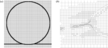
in Gerris. Figure 3 shows two views of the grid refinement for a case where the liquid viscosity is twice as high as in table 2 and the gas density ten times larger, so that
 $\mathit{Re}=1000$
and
 $\mathit{St}=2.26\times 10^{-6}$
, all the other parameters being the same as in figure 1.




We have checked that higher
 $h_{0}/D$
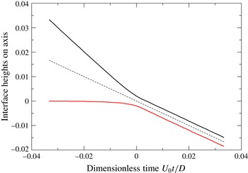
does not change the results significantly. This can also be verified from figure 4 where it can be seen directly that the simulation starts at a time
 $t_{0}=-D/(30U_{0})$
, much larger than the apparent time scale of the air-cushioning effect. In fact, the velocity of the south pole of the droplet is unperturbed until very short times of approximately
 $t\sim -5\times 10^{-3}D/U_{0}$
.
The dimensionless positions of the bottom of the droplet
 $z_{+}/D$
and the top of the film on the axis
 $z_{-}/D$
as functions of the dimensionless time
 $U_{0}t/D$
for
 $\mathit{St}=2.26\times 10^{-5}$
,
 $\mathit{Re}=1000$
and thus
 $J=0.5$
. The dashed line represents the mean position that decreases like
 $-0.5U_{0}t$
.

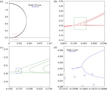
In figures 1 and 4, one can observe that a bubble is indeed entrapped by the impact due to the cushioning of the gas beneath the droplet. A very thin ejecta sheet is formed, followed by the growth of a thicker corolla. These figures do not, however, give a full account of the level of accuracy reached in the calculation, as shown in figure 5, where successive zooms of the interface are presented around the instant when the droplet contacts the liquid film. The large range of scales between the droplet diameter and the small features in figure 5(d) is apparent, figure 3 showing the corresponding grid.
Successive zooms of the interface around the time of jet formation
 $t_{j}$
for
 $\mathit{Re}=1000$
,
 $\mathit{We}=500$
and
 $\mathit{St}=2.26\times 10^{-6}$
so that
 $J=0.005$
. (a) shows the general view; (b) shows the zoom of the interface corresponding to the square traced on (a), and so on from (b) to (c) and from (c) to (d). In the first and last figures, the physical scales are shown based on a
 $D=2$
mm diameter drop for illustration. The
 $2~\unicode[STIX]{x03BC}\text{m}$
scale shown in the last figure corresponds in fact to twenty times the smallest mesh size of the numerical simulation. Remarkably, we observe a sequence of bubble entrapments before the jet is formed, in agreement with
 $J=(t_{b}/t_{g})^{3}\ll 1$
.

In particular, small bubbles (which are actually toroidal because of the axial symmetry) can be seen prior to the ejection of the thin liquid sheet. In this case, the liquid of the droplet has already made contact with the liquid layer before the jet formation, which is consistent with the small value of the jet number
 $J=0.005$
. Indeed, after the first entrapment of the bubble, the jet cannot emerge from the connected interfaces so that additional bubbles are eventually entrapped by the dynamics. These small toroidal bubble entrapments might in fact correspond to those observed in experiments recently (Thoroddsen et al.
Reference Thoroddsen, Thoraval, Takehara and Etoh2012). However, this is also strongly controlled by the size of the grid, as reconnection in the VOF methods depends on the grid size, questioning these bubbles’ existence in the continuum limit. In fact, a physical cutoff length is present in this problem, due to the mean free path in the gas under which the continuum mechanics is not valid and around which physical toroidal bubbles are eventually expected to form. Anyway, numerical simulations should not be performed at length scales below this cutoff. Considering again a
 $D=2~\text{mm}$
droplet for illustration, the finer grid size is
 $\unicode[STIX]{x0394}x\sim 8\times 10^{-8}~\text{m}$
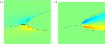
, only one order of magnitude away from the molecular length scales. Thus, the VOF reconnection, although not yet physically realistic, may, in the future, approach the length scales at which molecular forces trigger reconnection in the real world. Finally, the mechanism of jet formation can be observed in figure 6, where the vorticity field in the liquid and gas phases is shown prior to the ejection corresponding to the zoom of figure 5(d). It exhibits a vortex dipole at the origin of the jet, as already described in JZ03.
The vorticity field corresponding to figure 5(d): (a) in the liquid (the vorticity ranging here from
 $-800$
(blue) to 800 (red) in dimensionless units) and (b) in the gas (ranging from
 $-2000$
to 2000).

In the following, we investigate the different quantities involved in the splashing dynamics as the liquid and gas viscosities vary.
4.2 Spreading radius
One of the crucial quantities involved in the scaling analysis is the geometrical radius
 $r_{g}(t)$
that acts as the horizontal length scale. In order to verify that the horizontal scale behaves like
 $r_{g}(t)$
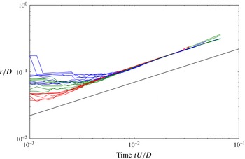
, we investigate the evolution with time of the spreading radius, defined as the point in the liquid where the velocity is maximal. Figure 7 shows the evolution of the spreading radius with time for all the simulations performed. The square-root scaling (
 $r_{g}(t)=\sqrt{DU_{0}t}$
) is observed over a large range of time with the same prefactor for all simulations. Remarkably, the figure shows that this geometrical argument for the horizontal characteristic length is particularly robust and that the liquid properties (viscosities, densities) only influence the dynamics at short times.
The dimensionless spreading radius, defined as the radius where the velocity is maximal in the liquid, as a function of the dimensionless time
 $U_{0}t/D$
, in a log–log plot for all the simulations performed in this study. The straight line indicates the slope
 $1/2$
corresponding to the geometrical law
 $r_{g}=\sqrt{DU_{0}t}$
shifted below for eye guiding. As suggested by this geometrical relation, the different curves all collapse onto a single one parallel to the expected law, showing that viscous, capillary and lubrication effects only alter slightly this dynamics. Differences can, however, be seen at short times.

4.3 Initial gas sheet formation
We now study the formation of the gas sheet and its scaling. The transition from free fall to air cushioning can be seen on the time history of the heights of the film and the bubble
 $z_{-}(r,t)$
and
 $z_{+}(r,t)$
. Figure 4 shows both heights
 $z_{-}(0,t)$
and
 $z_{+}(0,t)$
on the axis as a function of time for
 $\mathit{St}=2.26\times 10^{-5}$
and
 $\mathit{Re}=1000$
. This corresponds to a value of the air viscosity
 $10$
times its ordinary value, while the liquid is
 $8$
times more viscous than water. It is seen that the heights behave linearly until some time near
 $t=0$
(approximately
 $t\sim -5\times 10^{-3}D/U_{0}$
). The linear behaviour of
 $z_{+}(0,t)$
before impact is an indication that the bottom of the drop falls at the free fall velocity
 $U_{0}+O(g(t-t_{0}))$
(the gravity correction is even smaller than
 $\mathit{Fr}^{-1}$
due to the short time of observation) almost unperturbed from its initial value. At
 $t=0$
on the other hand the cushioning dynamics has fully set in. After time 0,
 $z_{+}(0,t)\sim z_{-}(0,t)\sim -U_{0}t/2$
and
 $z_{+}(0,t)-z_{-}(0,t)$
remains approximately constant. This half-velocity linear decrease of both
 $z_{+}(0,t)$
and
 $z_{-}(0,t)$
can be understood simply by momentum conservation as already suggested by Tran et al. (Reference Tran, de Maleprade, Sun and Lohse2013). The scale
 $h_{b}$
of the gas layer may thus conveniently be defined as
 $h_{b}=z_{+}(0,0)-z_{-}(0,0)$
.
To determine the scaling of
 $h_{b}$
two series of simulations have been performed at
 $\mathit{Re}=2000$
and
 $\mathit{Re}=800$
for variable Stokes number
 $\mathit{St}$
. Together with the numbers in table 1 these completely define the simulation parameters. The dimensionless height
 ${\hat{h}}_{b}=h_{b}/D$
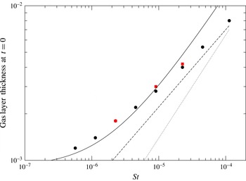
is plotted in figure 8 together with relation (2.26). The unknown turbulent friction coefficient
 $C_{1}$
has been fitted by trial and error to
 $C_{1}=0.75\pm 0.1$
.
Height scale
 $h_{b}/D$
of the gas layer as a function of the Stokes number for two values of the Reynolds number,
 $\mathit{Re}=800$
(red squares) and
 $\mathit{Re}=2000$
(black circles). The fit using equation (2.26) is shown (solid line) as well as the two scaling laws
 $\mathit{St}^{2/3}$
(dotted line) and
 $\mathit{St}^{1/2}$
(dashed line).

While the numerical data points are not exactly on top of the fit, the hypothesis of a transition from a
 ${\hat{h}}_{b}\rightarrow {\hat{h}}_{min}C_{1}\unicode[STIX]{x1D6FC}$
limit at small
 $\mathit{St}$
to a
 ${\hat{h}}_{b}\sim \mathit{St}^{n}$
behaviour at larger (but still small)
 $\mathit{St}$
is compatible with the data, with
 $n$
in some range around
 $2/3$
. However, it is worth remarking that the rightmost part of the graph is closer to a
 $1/2$
power-law behaviour, suggesting that the alternative scenario proposed by Klaseboer et al. (Reference Klaseboer, Manica and Chan2014) might be valid here. In order to test the scaling of
 ${\hat{h}}_{b}$
at very low
 $\mathit{St}$
, when the effect of
 $\unicode[STIX]{x1D6FC}=\unicode[STIX]{x1D70C}_{g}/\unicode[STIX]{x1D70C}_{l}$
is most marked, we show the results of a series of simulations at the smallest value of
 $\mathit{St}$
available in our simulations in figure 8 with variable
 $\unicode[STIX]{x1D70C}_{g}/\unicode[STIX]{x1D70C}_{l}$
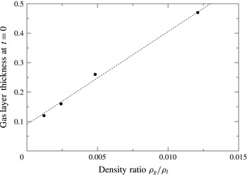
, keeping all other numbers constant. The results are plotted in figure 9. We observe a linear increase of
 ${\hat{h}}_{b}$
with
 $\unicode[STIX]{x1D70C}_{g}/\unicode[STIX]{x1D70C}_{l}$
, in agreement with the linear relation (2.29), with a constant in the limit
 $\unicode[STIX]{x1D70C}_{g}/\unicode[STIX]{x1D70C}_{l}\rightarrow 0$
that should depend on the Stokes number. Therefore, as the analysis on the pressure will confirm below, the alternative scaling of Klaseboer et al. (Reference Klaseboer, Manica and Chan2014) is not valid here and
 $\mathit{St}^{1/2}$
has to be seen as a best-fit scaling in the intermediate regime between
 ${\hat{h}}_{b}~C_{1}\unicode[STIX]{x1D6FC}$
at low
 $\mathit{St}$
and
 ${\hat{h}}_{b}\sim \mathit{St}^{2/3}$
at large
 $\mathit{St}$
(Jian et al.
Reference Jian, Josserand, Ray, Duchemin, Popinet and Zaleski2015).
Height scale
 $h_{b}/D$
of the gas layer as a function of
 $\unicode[STIX]{x1D70C}_{g}/\unicode[STIX]{x1D70C}_{l}$
for
 $\mathit{St}=5.67\times 10^{-7}$
and
 $\mathit{Re}=2000$
with all other parameters as in table 1.

4.4 Impact pressure
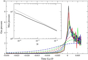
In order to investigate quantitatively the various mechanisms involved in the impact dynamics and the jet formation, we follow the evolution in time of the maximum pressure on the axis in the gas layer in figure 10 for different Stokes numbers at constant
 $\mathit{Re}=2000$
, around the time of jet formation. We see a very large pressure peak at the formation of the jet, up to ten times the Bernoulli pressure
 $\unicode[STIX]{x1D70C}_{l}U_{0}^{2}$
for the smallest
 $\mathit{St}$
value. This peak is delayed and decreased as the
 $\mathit{St}$
value increases. The insert of figure 10 plots the value of this peak pressure as a function of
 $\mathit{St}$
, showing a very good agreement with the scaling
 $\mathit{St}^{-1/3}$
predicted in (2.32) by balancing the impact pressure of the drop with the lubrication pressure of the gas. This dependence of the pressure field on the Stokes number is clearly in disagreement with the Bernoulli argument proposed in Klaseboer et al. (Reference Klaseboer, Manica and Chan2014). Together with the variations of
 ${\hat{h}}_{b}$
described above, it indicates that the lubrication is the dominant regime in the air cushioning, in opposition to the alternative scenario of Klaseboer et al. (Reference Klaseboer, Manica and Chan2014). We should also emphasize here that this high pressure in the gas layer can lead to compression of the gas, as happens for drop impact on a solid substrate (Mandre et al.
Reference Mandre, Mani and Brenner2009; Riboux & Gordillo Reference Riboux and Gordillo2014). Indeed, taking for instance the typical values for water drop impact
 $\unicode[STIX]{x1D70C}_{l}=1000~\text{kg}~\text{m}^{-3}$
and
 $U_{0}\sim 4~\text{m}~\text{s}^{-3}$
, we obtain an additional pressure in the air of the order of three-fourths of the atmospheric pressure.
The pressure in the gas layer in the cushioning regime, defined as the maximum gas pressure on the axis down the drop. The dimensionless pressure (using
 $\unicode[STIX]{x1D70C}_{l}U_{0}^{2}$
) is plotted as a function of the dimensionless time
 $U_{0}t/D$
for a fixed
 $\mathit{Re}=2000$
and for varying Stokes number
 $\mathit{St}=5.66\times 10^{-7}$
,
 $1.13\times 10^{-6}$
,
 $2.26\times 10^{-6}$
,
 $4.52\times 10^{-6}$
,
 $9.05\times 10^{-6}$
,
 $2.26\times 10^{-5}$
,
 $4.52\times 10^{-5}$
and
 $1.13\times 10^{-4}$
, from top to bottom. The insert shows the maximum pressure over time of these curves as a function of the Stokes number. The dashed line represents the expected
 $\mathit{St}^{-1/3}$
scaling following the prediction (2.32).

4.5 Ejecta sheet velocity
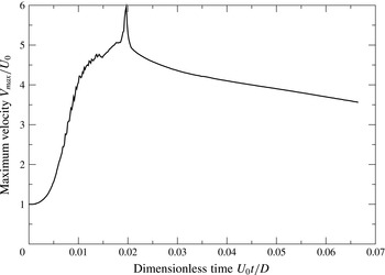
The ejecta sheet velocity can be measured by following the evolution of the velocity maximum in the liquid. This quantity is indeed an interesting proxy for several measurements and is easier and less ambiguous to measure than the ejecta thickness, which varies widely at its base. Figure 11 shows the maximum dimensionless velocity as a function of the dimensionless time shifted to the beginning of the simulation
 $U_{0}t/D$
(remember that the origin of time
 $t=0$
corresponds to the time at which the geometrical falling sphere would interact with the liquid layer), for
 $\mathit{Re}=1000$
and
 $\mathit{St}=9.05\,10^{-6}$
, with other parameters defined in table 1. It is seen that the maximum velocity deviates from the initial velocity
 $U_{0}$
around
 $-U_{0}t_{b}/D\simeq -0.03$
, that is, when the droplet approaches the liquid film, after which it increases rapidly, then reaches a maximum and decreases slowly. Finally, it has a tell-tale ‘spike’ at the instant of jet ejection marking
 $t_{j}$
, the time of emergence of the ejecta sheet.
The maximum velocity
 $V_{max}/U_{0}$
as a function of the dimensionless time for
 $\mathit{Re}=1000$
and
 $\mathit{St}=9.05\times 10^{-6}$
, so that
 $J=0.082$
. Other parameters as in table 1.

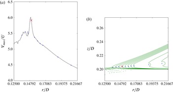
Indeed, figure 12 shows the value of the maximum velocity in the liquid and the location at which it is reached as time varies for the same parameters. It is clear in that case that the sharp peak corresponding to the maximum velocity also corresponds to the time of reversal of the curvature of the interface, marking the beginning of the ejection of the jet. Detailed investigations show that in all cases investigated in this paper, this spike corresponds exactly to the time of formation of the ejecta sheet, and that the maximum is located at its base.
However, zooming in on the base of the jet, as done in figure 5(d), shows that a set of tiny bubbles has already formed, meaning that first contact between the drop and the sheet has already occurred before the jetting time in figure 12. In other words, in this case, contact happens markedly before jet formation, in agreement with the small value of
 $J=0.082$
.
(a) Maximum velocity as a function of the radius where it is located for different times (indicated by the blue
 $+$
signs). (b) Interface profiles corresponding to the same time. The position at which the velocity is maximum is again marked by blue
 $+$
symbols. The location of the maximum velocity at time of reversal of the interface curvature, marking the beginning of jet ejection, is marked with a red
 $\times$
sign.

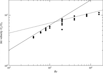
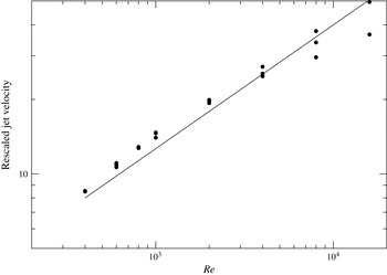
Defining the speed of the jet as this spike velocity, we can investigate how the jet velocity depends on the Reynolds numbers for the different Stokes numbers simulated. This velocity is shown in figure 13 as a function of the Reynolds number in order to check the validity of the scaling law (2.5):
 $U_{j}\propto \sqrt{\mathit{Re}}U_{0}$
. The results are puzzling: indeed, while a reasonably good agreement for ‘low’ Reynolds numbers (below 1000) is observed, important deviations appear at larger Reynolds numbers where another scaling is apparently at play, consistent with a
 $\mathit{Re}^{n}$
fit with
 $n\sim 1/5$
. Moreover, it is interesting to notice that the jet velocity shows almost no dependence on the Stokes number below
 $\mathit{Re}\sim 1000$
, as suggested by the viscous length theory of JZ03, while a small dependence can be identified in the higher-Reynolds-number regime.
The jet velocities
 $U_{j}/U_{0}$
as a function of the Reynolds number for all the simulations performed in this study, in a log–log plot. The predicted power-law relation (2.5) is also plotted, showing only a reasonable agreement at Reynolds numbers lower than
 $1000$
(solid line). For higher Reynolds numbers another scaling appears, consistent with a
 $\mathit{Re}^{1/5}$
law (dashed line). For
 $\mathit{Re}=2000$
, where many Stokes numbers have been considered, we note a slight dependence of the velocity on the Stokes number; the higher the Stokes number, the lower the jet velocity.

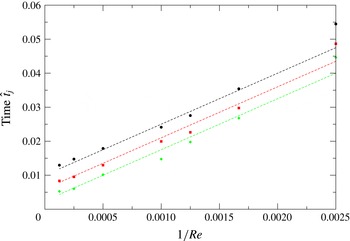
 $\hat{t}_{j}=U_{0}t_{j}/D$
as a function of the inverse of the Reynolds number (
 $1/\mathit{Re}$
) for different Stokes numbers: black circles
 $\mathit{St}=2.26\times 10^{-5}$
, red squares
 $\mathit{St}=9.05\times 10^{-6}$
and green diamonds
 $\mathit{St}=2.26\times 10^{-6}$
. Parallel dashed straight lines are drawn for each Stokes number for guiding the eye.

In order to better understand this discrepancy between the predicted law and the numerical results, the dimensionless time
 $\hat{t}_{j}=U_{0}t_{j}/D$
of the jet formation needs to be investigated. Two scaling laws for this time are in competition, the ratio between these two time scales being quantified by the number
 $J$
. On the one hand, the viscous length theory without accounting for the gas lubrication effect suggests that
 $\hat{t}_{j}\propto 1/\mathit{Re}$
(relation (2.6)); on the other hand, the cushioning of the gas suggests that this effect is delayed by the time
 $\hat{t}_{b}\sim \mathit{St}^{2/3}$
(relation (2.30)).
First of all, figure 14 exhibits parallel straight lines when plotting
 $\hat{t}_{j}$
as a function of
 $1/\mathit{Re}$
for three different Stokes numbers, indicating a linear relationship between
 $\hat{t}_{j}$
and
 $1/\mathit{Re}$
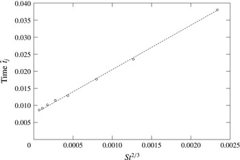
. However, although the straight lines have similar slope, they have different origins for each Stokes number, suggesting that a time delay depending on the Stokes number has to be considered. This can be seen in figure 15 where
 $\hat{t}_{j}$
is plotted, for
 $\mathit{Re}=2000$
as a function of
 $\mathit{St}^{2/3}$
, as suggested by the theoretical law obtained for the bubble entrapment
 $\hat{t}_{b}$
(2.30).
 $\hat{t}_{j}$
as a function of the Stokes number to the power predicted by the theory (2.30),
 $\mathit{St}^{2/3}$
, for constant Reynolds number
 $Re=2000$
. The dashed line indicates a linear relationship between these two quantities.

Again, a good straight line is observed, demonstrating eventually that
 $\hat{t}_{j}$
obeys the following relation:
 $$\begin{eqnarray}\hat{t}_{j}=A_{1}\,\mathit{St}^{2/3}+B_{1}\,\mathit{Re}^{-1}.\end{eqnarray}$$
This relation can be written using the parameter
 $J$
,
 $$\begin{eqnarray}\mathit{Re}\,\hat{t}_{j}=A_{1}J^{1/3}+B_{1},\end{eqnarray}$$
with
 $A_{1}$
and
 $B_{1}$
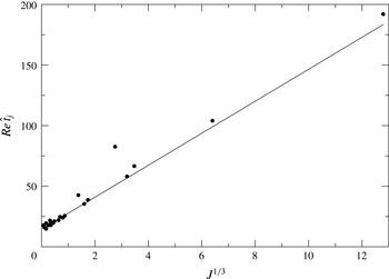
as fitting parameters. Figure 16 confirms this relation, by plotting
 $\hat{t}_{j}\,\mathit{Re}$
as a function of
 $J^{1/3}$
for all the simulations performed here. A good collapse of the data is obtained that is well fit by the formula (4.2) with
 $A_{1}=13.2$
and
 $B_{1}=14.5$
.
The data (black circles) for the jet formation time
 $\mathit{Re}\,\hat{t}_{j}$
plotted as a function of
 $J^{1/3}$
for all the simulations performed in this study. The data align almost perfectly along a line as suggested by the formula (4.2), which is used to fit the data (solid curve) using
 $A_{1}=13.2$
and
 $B_{1}=14.5$
.

The above study suggests that the impact dynamics can be decomposed into two dynamical stages: the first one is dominated by the cushioning dynamics involving a
 $\mathit{St}^{2/3}$
time scale dependence. Then, the ejection mechanism of the liquid sheet arises after a time delay proportional to
 $1/\mathit{Re}$
.
(a) Maximum velocity
 $V_{max}/U_{0}$
as a function of time for
 $\mathit{St}=2.26\times 10^{-6}$
and for various Reynolds numbers (
 $\mathit{Re}=400$
,
 $600$
,
 $800$
,
 $1000$
,
 $2000$
,
 $4000$
,
 $8000$
and
 $16\,000$
for the curves from bottom to top). (b) Same curves where the velocity has been rescaled by the theoretical prediction
 $\sqrt{\mathit{Re}}$
. In this case, the order of the curves for increasing Reynolds numbers is reversed, ranging from top to bottom. The initial velocity
 $U_{0}$
has been subtracted at short time for clarity.

These different regimes can now be investigated through the evolution of the maximum velocity as function of time for all the parameters simulated here. Firstly, we show in figure 17(a) the maximum dimensionless velocity
 $\hat{V}_{max}=V_{max}/U_{0}$
as a function of the dimensionless time
 $\hat{t}=U_{0}t/D$
for different Reynolds numbers and for a fixed Stokes number of
 $\mathit{St}=2.26\times 10^{-6}$
, where it can be observed that the higher the Reynolds number, the higher is the velocity, as expected by the JZ03 prediction (2.5). This is investigated in figure 17(b), where these dimensionless velocities are rescaled by the predicted scaling
 $\sqrt{\mathit{Re}}$
and plotted as a function of time. If a reasonable collapse of the curve is obtained, firstly at short times and for Reynolds numbers below 1000, the curves for higher Reynolds numbers deviate from the master curve starting at the dimensionless time
 $\hat{t}_{j}$
of the jet formation. As expected, however, the time
 $\hat{t}_{j}$
decreases as the Reynolds number increases, but for the high Reynolds numbers, the velocity peak appears during the velocity rise, indicating that eventually the two mechanisms of air cushioning and jet formation interact. Somehow, the air-cushioning effect is interrupted by the ejection of the liquid sheet. This explains why the jet velocity at high Reynolds number does not follow the prediction (2.5). On the other hand, for lower Reynolds numbers (and hence lower jet numbers
 $J$
), one can see that the two mechanisms of air cushioning and jet formation are well separated in time.
(a) Maximum velocity
 $V_{max}/U_{0}$
as a function of time for
 $\mathit{Re}=200$
and for various Stokes numbers (
 $\mathit{St}=5.65\times 10^{-7}$
,
 $1.13\times 10^{-6}$
,
 $2.26\times 10^{-6}$
,
 $4.52\times 10^{-6}$
,
 $9.05\times 10^{-6}$
and
 $2.26\times 10^{-5}$
for the curves from left to right). (b) For three Stokes numbers
 $2.26\times 10^{-6}$
,
 $9.05\times 10^{-6}$
and
 $2.26\times 10^{-5}$
the maximum velocity rescaled by
 $\sqrt{\mathit{Re}}$
are shown for different Reynolds numbers ranging from
 $400$
to 16 000, in a log–linear plot. Three sets of curves can be identified, one for each Stokes number, from left to right as the Stokes number increases. Here, the initial velocity
 $U_{0}$
has been subtracted at short time for clarity.

The dependence of the dynamics on the Stokes numbers can be observed in figure 18(a) where the maximum velocity
 $V_{max}/U_{0}$
is shown at
 $\mathit{Re}=2000$
for different Stokes numbers. As expected by lubrication theory, the higher the Stokes number the slower the rise of the velocity. On the other hand, since the formation of the jet is delayed by this cushioning dynamics, we observe that the velocity peak is also delayed and is slightly decreasing as the Stokes number increases. This is in contradiction with the JZ03 initial prediction (2.5) that was obtained by neglecting the gas cushioning, explaining why this relation is not verified. The velocity curves are rescaled in figure 18(b) by
 $\sqrt{\mathit{Re}}$
as suggested by the prediction (2.5) for three Stokes numbers and different Reynolds numbers (up to
 $8$
for a given Stokes number). The curves are arranged in three sets (one for each Stokes number for all the Reynolds numbers) in time, showing clearly that the Stokes number influences mostly the accelerating regime. The
 $\sqrt{\mathit{Re}}$
predicted scaling for the jet velocity is seen from the maximum of these curves, which are very close to each other. However, as observed in the jet velocity curve shown in figures 13 and 17, many curves do not reach this maximum because of the cushioning dynamics.
The curves for the three Stokes numbers in figure 18 result in three different curves which are roughly translated on the logarithmic time axis, suggesting a scaling dependence on the Stokes number. The cushioning being characterized by the bubble entrapment time
 $t_{b}$
, it is tempting to rescale the time by
 $t_{b}$
, which scales at first order like
 $U_{0}t/(D\,\mathit{St}^{2/3})$
. In fact, the best rescaling of the curve is obtained using the precise dependence of
 $t_{b}$
on the Stokes number involving the inertial correction, formula (2.31), as shown in figure 19. There, a very good collapse of all the curves simulated in the study is obtained, showing that the jet rise follows cushioning dynamics. These results suggest that in this first dynamical stage, where the air cushioning is dominant, the velocity obeys the following relation (taking the first-order approximation
 $\hat{t}_{b}\sim \mathit{St}^{2/3}$
):
 $$\begin{eqnarray}V_{max}\sim \sqrt{\mathit{Re}}U_{0}\,f_{c}[(U_{0}t/D)\,\mathit{St}^{-2/3}],\end{eqnarray}$$
using here as a first-order approximation
 $\hat{t}_{b}\sim \mathit{St}^{2/3}$
;
 $f_{c}$
is the universal function that describes this cushioning regime. Immediately after the jet formation, and in a kind of plateau region, the velocity at the base of the jet does scale with
 $\mathit{Re}^{1/2}$
for intermediate Reynolds numbers, as predicted by (2.5), while it departs slightly from this scaling for high Reynolds numbers. Although this evolution is in agreement with the initial theory of JZ03, it is important to note that the velocity is not constant and is in fact decreasing with time after the jet formation time
 $t_{j}$
. This second stage is determined by the jet dynamics and is a priori not influenced by the surrounding gas. Recalling that the time scale for the jet formation in the absence of gas cushioning is
 $t_{g}\sim D/(\mathit{Re}\,U_{0})$
, it is tempting to investigate the evolution with time of the maximum velocity as a function of the rescaled time
 $t/t_{g}=\mathit{Re}\,U_{0}t/D$
, following
 $$\begin{eqnarray}V_{max}\sim \sqrt{\mathit{Re}}\,U_{0}\,f_{j}(\mathit{Re}\,U_{0}t/D),\end{eqnarray}$$
where
 $f_{j}$
is the universal function describing this second dynamical stage. The rescaled velocities
 $V_{max}/\sqrt{\mathit{Re}}\,U_{0}$
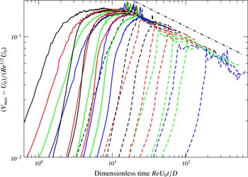
are shown in figure 20 as a function of the rescaled time
 $\mathit{Re}\,U_{0}t/D$
for all the simulations performed in this study. Remarkably, a good collapse of the curves is observed for the large-time dynamics, i.e. for the time after the jet formation (
 $t>t_{j}$
). The dashed line in this log–log plot exhibits a good fit of the data in this regime, using a
 $-3/10$
power law, so that the maximum velocity obeys eventually for
 $t>t_{j}$
:
 $$\begin{eqnarray}V_{max}\sim \sqrt{\mathit{Re}}\,U_{0}\,f_{j}(\mathit{Re}\,U_{0}t/D)\sim \sqrt{\mathit{Re}}\,U_{0}\left(\frac{\mathit{Re}U_{0}t}{D}\right)^{-3/10}.\end{eqnarray}$$
Rescaled velocities by
 $\sqrt{\mathit{Re}}$
for all the simulations performed in this study as a function of the rescaled time (
 $t/t_{b}$
), where
 $t_{b}$
is computed using formula (2.31). The initial velocity
 $U_{0}$
has been subtracted at short time for clarity.

The rescaled maximum velocity
 $V_{max}/(\sqrt{\mathit{Re}}\,U_{0})$
shown as a function of the rescaled time
 $\mathit{Re}\,U_{0}t/D$
based on the geometrical time scale for jet ejection
 $t_{g}$
(see relation (2.6)) in a log–log plot. The dot-dashed line indicates the power-law scaling
 $(\mathit{Re}\,U_{0}t/D)^{-3/10}$
. The initial velocity
 $U_{0}$
has been subtracted at short time for clarity.

This behaviour suggests an explanation for the selection of the maximum jet velocity, considering that this latter regime starts at the jetting time
 $t_{j}$
. Recall first the asymptotic scalings observed for the jet maximum velocity shown in figure 13, namely
 $V_{max}\sim \sqrt{\mathit{Re}}\,U_{0}$
for
 $\mathit{Re}\leqslant 1000$
and
 $V_{max}\sim \mathit{Re}^{1/5}\,U_{0}$
otherwise. Interestingly, these two asymptotics are consistent with the function
 $f_{j}$
(4.5) when considering the two asymptotics for the jet formation time
 $t_{j}$
. Indeed, for
 $\mathit{Re}\leqslant 1000$
we have
 $t_{j}\sim D/(\mathit{Re}\,U_{0})$
so that, using (4.5), the first scaling is
 $V_{max}\sim \sqrt{\mathit{Re}}\,U_{0}$
. On the other hand, in the other regime,
 $\mathit{Re}\geqslant 1000$
, for which
 $t_{j}\sim \mathit{St}^{2/3}D/U_{0}$
, we obtain
 $$\begin{eqnarray}V_{max}\sim \sqrt{\mathit{Re}}\,U_{0}(\mathit{Re}\,\mathit{St}^{2/3})^{-3/10}\sim \mathit{Re}^{1/5}\,\mathit{St}^{-1/5},\end{eqnarray}$$
giving, remarkably, the velocity scaling for large Reynolds numbers. Note also that it predicts a power-law dependence on the Stokes number that we have not tested so far, although it can be qualitatively seen in figure 13. Finally, using the formula (4.2) for
 $\hat{t}_{j}$
,
 $$\begin{eqnarray}\mathit{Re}\,\hat{t}_{j}=A_{1}J^{1/3}+B_{1},\end{eqnarray}$$
and formula (4.5), we obtain an effective formula for the maximum jet velocity:
 $$\begin{eqnarray}\frac{V_{max}}{\sqrt{\mathit{Re}}}=C_{1}\frac{U_{0}}{(A_{1}J^{1/3}+B_{1})^{3/10}},\end{eqnarray}$$
where the initial theoretical law of JZ03
 $V_{max}\propto \sqrt{\mathit{Re}}\,U_{0}$
is corrected by the cushioning dynamics quantified by the number
 $J$
.
Black circles: the numerically measured jet velocity rescaled by the dependence in the
 $J$
number following formula (4.8),
 $(A_{1}J^{1/3}+B_{1})^{3/10}U_{j}/U_{0}$
, as a function of the Reynolds number. The
 $\sqrt{\mathit{Re}}$
law is drawn (solid line) showing the validity of (4.8) using
 $C_{1}=0.4$
.

This formula is tested in figure 21 where the measured jet velocity for all the numerical simulations performed here, rescaled by the factor
 $U_{0}/(A_{1}J^{1/3}+B_{1})^{3/10}$
, is plotted as a function of the Reynolds number, showing the validity of the formula (4.8).
4.6 Bubble entrapment versus jet formation?
We have observed in our simulations that, in most cases, the jet emergence is simultaneous with the connection of the two interfaces, that is, the bubble becomes trapped at the time of jet formation. In fact, the situation is more complex and can be analysed using the jet number
 $J$
that quantifies the transition between a regime where the air cushioning is insignificant (
 $J\ll 1$
) and a regime where it is dominant (
 $J\gg 1$
). When the air cushioning is insignificant, we find that the jet forms at the geometrical time
 $t_{g}\gg t_{b}$
(recall that
 $J=t_{b}^{3}/t_{g}^{3}$
), with a jet velocity of the order of
 $\mathit{Re}^{1/2}$
, as predicted earlier in JZ03. Moreover, we find that this velocity scale is present before jet formation, indicating the existence of a large velocity in the droplet prior to the formation of the jet. This large velocity (asymptotically infinitely larger than
 $U_{0}$
) is indicative of the focusing of the liquid velocity in a small region inside the droplet prior to the emergence of the jet. In this regime, where the gas cushioning effect is insignificant, the first bubble entrapment occurs before jet formation. A trace of this is seen in the presence of the small bubbles in figure 5(d) before jet formation. This is even clearer in figure 22, which shows the details of the interface dynamics between the time of first contact between the drop and the liquid film and the formation of the jet, for
 $\mathit{Re}=2000$
and
 $\mathit{St}=5.66\times 10^{-7}$
, leading to
 $J=2.56\times 10^{-3}$
. After the first contact between the drop and the liquid layer, no jet can form since
 $t_{b}\ll t_{g}$
, so additional bubbles (toroidal here because of the axial symmetry) are entrapped by the falling drop before the jet can eventually escape the falling droplet.
Zoomed-in pictures of the connection of the upper interface of the drop with the liquid layer for
 $\mathit{Re}=2000$
and
 $\mathit{St}=5.66\times 10^{-7}$
, the other parameters being those of table 1. The interfaces are shown at times
 $U_{0}t/D=3.67\times 10^{-3}$
(a),
 $5.33\times 10^{-3}$
(b),
 $7\times 10^{-3}$
(c) and
 $1.03\times 10^{-2}$
(d). The jet number
 $J=2.56\times 10^{-3}\ll 1$
and we thus observe that after the first connection of the two interfaces in (a), small bubbles are created at the front of the connection by the retraction of the thin gas layer that is still between the falling drop and the liquid film, (b) and (c), until the jet emerges on (d). On the other side of the connected region, the thin air film forming the entrapped large bubble is also retracting by capillarity.

We observe that a delay exists between the first connection of the interfaces (figure 22 a) and the jet formation (figure 22 d), during which small bubbles are entrapped by the thin gas film dynamics.
On the other hand, in the regime where
 $J$
is large (and similarly
 $t_{b}\gg t_{g}$
) it is not clear how jet formation and air bubble entrapment interact, but one expects that no small bubbles are entrapped and that the jet is formed simultaneously to the bubble entrapment. This is illustrated in figure 23 for
 $\mathit{Re}=16\,000$
and
 $\mathit{St}=2.26\times 10^{-7}$
, so that
 $J=2700$
, where the jet expands as soon as the drop and the liquid layer have merged.
Zoomed-in pictures of the connection of the upper interface of the drop with the liquid layer for
 $\mathit{Re}=16\,000$
and
 $\mathit{St}=2.26\times 10^{-5}$
, the other parameters being those of table 1. The interface is shown at times
 $U_{0}t/D=0.01167$
(a),
 $0.01182$
(b),
 $0.012$
(c) and
 $0.0123$
(d). The jet number
 $J=2700\gg 1$
and the first connection of the two interfaces occurs between (a) and (b). No additional bubbles are entrapped and the jet is directly emerging from this connection, (d).

5 Conclusion
In our numerical experiments, we have focused on the jet velocity and the effect of the gas layer on the impact of a droplet onto a thin film of the same liquid. The formation and the scaling of the gas layer were analysed. As the gas layer cushions the impact, a large peak in pressure is observed which scales like
 $P_{imp}\sim \unicode[STIX]{x1D70C}_{l}U_{0}^{2}\,\mathit{St}^{-1/3}$
, as predicted by lubrication theory, leading eventually to bubble entrapment. The formation of the gas layer itself shows interesting symmetry properties between the dynamics of the droplet surface
 $z_{+}$
and the dynamics of the liquid layer
 $z_{-}$
. The two are equally deformed at the time
 $t=0$
. The time during which deformation sets up is very short compared to the characteristic time
 $D/U_{0}$
and also to the time of free fall
 $h_{0}/U_{0}$
. The corresponding layer thickness exhibits an intermediate regime between the
 $D\,\mathit{St}^{2/3}$
scaling outlined by lubrication theory and an inertial regime independent of the Stokes number at low
 $\mathit{St}$
, confirming that the dominant mechanism for the air cushioning is determined by the lubrication regime. The dependence of the layer thickness shows in addition a linear relationship with the density ratio
 $\unicode[STIX]{x1D70C}_{g}/\unicode[STIX]{x1D70C}_{l}$
(figure 9), as predicted by theory (2.29).
The results for the jetting time
 $t_{j}$
exhibit another interplay between the gas cushioning (whose time scale is determined by
 $\mathit{St}^{2/3}$
, neglecting as a first approximation the inertial correction) and the liquid viscous boundary layer mechanism described in JZ03 (with a time scale of
 $1/\mathit{Re}$
). This interplay is very well described by the new dimensionless parameter
 $J=\mathit{St}^{2}\,\mathit{Re}^{3}$
introduced in this work. This number
 $J$
characterizes indeed the influence of the gas cushioning on the splashing dynamics. At large
 $J$
, the jet formation is delayed by the bubble entrapment, while at small
 $J$
, a rosary of bubbles is formed before the liquid jet can emerge. Finally, we have shown here that these coupled mechanisms explain how the jet velocity varies with the impact parameters.