





1. Introduction
Although flapping foils have been extensively investigated under sinusoidal or otherwise periodic motions (Triantafyllou et al. Reference Triantafyllou, Triantafyllou and Grosenbaugh1993; Anderson et al. Reference Anderson, Streitlien, Barrett and Triantafyllou1998; Wu et al. Reference Wu, Zhang, Tian, Li and Lu2020), relatively little attention has been devoted to irregular or aperiodic flapping. This gap is notable because many biological propulsors, including fish, birds and insects, rarely maintain strictly periodic kinematics in natural locomotion. Instead, their flapping motions are often perturbed by environmental disturbances, unsteady body dynamics or active control strategies, resulting in inherently irregular (non-periodic) patterns (Dickinson et al. Reference Dickinson, Lehmann and Sane1999; Srygley & Thomas Reference Srygley and Thomas2002; Lauder & Drucker Reference Lauder and Drucker2002). The flow physics associated with such irregular motion are expected to differ significantly from sinusoidal motions, with short bursts of large acceleration and rapid changes in effective angle-of-attack (AOA) likely dominating thrust and lift generation. Understanding these unsteady mechanisms is essential for linking biological observations to flow physics and for developing robust bioinspired propulsion concepts that can operate efficiently and even harness the energy in realistic environments.
Schematic of surface craft with a wave-assisted propulsion (WAP) system. The schematic is not drawn to scale.

One system where the performance of flapping foils undergoing irregular motion is particularly relevant is for WAP systems which harness the energy of ocean waves via flapping foils to generate thrust for surface vessels. The WAP systems can be categorized based on how the propulsive element is attached to the hull. In rigid hull-integrated systems (e.g. Bøckmann & Steen (Reference Bøckmann and Steen2013), and commercial retractable bow foils such as Wavefoil systems), the foil is fixed to the vessel structure via stiff struts or retractable modules and follows the vessel’s full rigid-body motion without independent degrees of freedom (DOF). The second type of WAP systems include compliant attachments (e.g. Wave Glider developed by Liquid Robotic), where the attachment is not rigid but allows relative motion between the foil and the surface vessel which employ flexible connections such as cables or ropes, allowing some relative motion between the surface vessel and the foil system. The third type of WAP systems are the rigid-heave but free-pitch foil systems which includes a rigid-heave but free-pitch foil, in which the foil is attached to stiff support so that it follows the vessel’s heave motion, while being free (or spring-mounted) to rotate in pitch; this arrangement allows passive rectification of oscillatory wave motion into net thrust. Among these categories, the third, rigid-heave with free-pitch foil configuration (figure 1) provides a good compromise between system complexity and performance. This design also captures the essential hydroelastic energy-extraction mechanism while remaining analytically and experimentally tractable. Due to these factors, several studies have addressed this configuration (e.g. Isshiki Reference Isshiki1982; Belibassakis et al. Reference Belibassakis, Filippas and Papadakis2021; Chan et al. Reference Chan, Wang, Yang and Zang2024). We have therefore focused our studies, including the current paper, on this configuration.
Another way to classify the WAP systems is by their distance from the free surface. For shallow-water or near-surface systems such as the Suntory Mermaid II, the foil operates at depths comparable to the wave amplitude. The free-surface effects can be important for such configurations. In deep-water WAP systems, such as the Wave Glider (Liquid Robotics; Hine et al. (Reference Hine, Willcox, Hine and Richardson2009)) or Wavefoil systems (Bøckmann & Steen Reference Bøckmann and Steen2016) in certain operating conditions, the foil operates sufficiently far below the free surface. In such configurations, free-surface effects (e.g. wave-induced pressure variations and proximity effects) are significantly attenuated and the dominant influence of the waves on the foil is through the imposed heaving motion. The present study is focused on such deep-water WAP systems.
Most of the previous studies (Yang et al. Reference Yang, Shi and Wang2019; Qi et al. Reference Qi, Jiang, Jia, Zou and Zhai2020; Zhang et al. Reference Zhang, Xu, Ding and Hu2022, Reference Zhang, Yue, Zhou, Gao, Zhang and Chen2024b ; Xing & Yang Reference Xing and Yang2023; Xu et al. Reference Xu, Jing, Liao, Tang, Ma, Liu and Pang2024; Zhang et al. Reference Zhang, Han, Hu, Chen, Li, Gao and Chen2024a ) employ a hydrofoil mounted beneath the hull and connected to the supporting strut through a torsional spring (figure 1). Vertical oscillations of the vessel induced by surface waves drive a periodic heaving motion of the submerged foil. The coupling between hydrodynamic forces and the restoring moment of the torsional spring results in a passive pitching response. The combined heaving and pitching kinematics generate thrust, which can function either as the main propulsion mechanism or as a supplementary contribution to the vessel’s conventional propulsion system. Surge is commonly omitted as a dynamic DOF in WAP simulations. Experimental seakeeping data in regular head waves show that surge response amplitudes are typically small (except in very long waves), whereas surge becomes more pronounced in following waves (Saettone et al. Reference Saettone, Taskar, Steen and Andersen2021); hence many WAP studies in head seas prescribe mean forward speed and neglect surge as a dynamic DOF.
In realistic ocean environments, wave fields are inherently irregular, exhibiting variability in frequency, amplitude, wavelength and direction. Such irregularity is typically represented through statistical descriptions in the form of wave spectra, which specify the distribution of wave energy across frequencies. Among the commonly adopted spectral models, the Bretschneider spectrum is widely used to characterize fully developed seas (Bretschneider 1959), whereas the JONSWAP (joint North Sea wave analysis project) spectrum provides a more accurate representation of developing seas, particularly in coastal and limited-fetch regions (Hasselmann et al. Reference Hasselmann1973). In this study, irregular waves are modelled using the Bretschneider spectrum. Figure 2(a) shows the non-dimensional form of the Bretschneider spectrum along with a reference regular wave included for comparison. The reference regular wave is defined such that its total energy equals the integrated energy of the irregular spectrum,
 \begin{align} E_{\textit{irr}} = \rho g \int _0^{\infty } S(f){\rm d}f = \rho g \frac {H_s^2}{16} , \end{align}
(a) Non-dimensional Bretschneider wave energy spectrum for irregular waves. (b) Three realizations (R1, R2 and R3) of irregular waves generated from the Bretschneider spectrum for
 $H_s^*=0.62$
and St
 $_C=0.12$
.

where
 $S(f)$
is the spectral energy density and
 $H_s$
represents significant wave height which is a standardized statistical value representing the average height of the highest one-third of waves in a sea-state. For a monochromatic regular (i.e. sinusoidal) wave of amplitude
 $A$
, the average wave energy per unit surface area is given by
 \begin{align} E_{\textit{reg}} = \frac {1}{8} \rho g A^2. \end{align}
Equating
 $E_{\textit{irr}} = E_{\textit{reg}}$
yields the amplitude
 $A$
of the equivalent regular wave. To represent this wave consistently within the spectral framework, its energy is concentrated into a single frequency bin of width
 $\Delta f$
centered at the chosen frequency. Accordingly, the spectral ordinate of the regular wave is determined from the condition
 \begin{align} S_{\textit{reg}}(f)\Delta f = E_{\textit{reg}}, \end{align}
which ensures that the spectral contribution of the regular wave reflects the same total energy as the irregular spectrum. Figure 2(b) illustrates the stochastic variability of irregular seas by showing three independent realizations of the irregular wave field, plotted together with the equal-energy regular wave for reference.
A few studies have addressed the influence of irregular waves on WAP systems. Filippas & Belibassakis (Reference Filippas and Belibassakis2014) analysed the hydrodynamic performance of actively controlled hydrofoils beneath the free surface and demonstrated their capability to generate thrust under irregular sea conditions represented by the Bretschneider spectrum. In a related study, Politis & Politis (Reference Politis and Politis2014) investigated hydrofoils subjected to irregular heave motions, also modelled with the Bretschneider spectrum, in combination with active pitching. They further proposed a control strategy that dynamically adjusts the pitch angle to improve propulsive efficiency. More recently, Feng et al. (Reference Feng, Wang, Jiang, Zhang, Deng and Chang2025) developed a reduced-order dynamical model of a wave glider operating in irregular seas described by the JONSWAP spectrum, showing that stiffer torsional springs are required in higher-energy wave environments to maximize thrust. These findings highlight that the variability inherent in irregular seas can cause significant changes in both performance and dynamic response of wave gliders across operational conditions. Despite progress in understanding multibody motion interactions and spring-stiffness effects, the majority of design approaches still assume regular, well-characterized wave conditions. As a result, the optimal selection of WAP foil parameters for robust performance in realistic, irregular sea-states remains an open research question.
In our earlier work (Raut et al. Reference Raut, Seo and Mittal2024), we examined the influence of pivot location and torsional spring stiffness on the thrust generation of WAP systems through the use of energy maps, and proposed a predictive model that estimates thrust from foil kinematics based on the phenomenology of leading-edge vortex (LEV) dynamics. Building upon this, we further investigated multifoil arrangements (Raut et al. Reference Raut, Seo and Mittal2025a ), demonstrating how the wake shed by an upstream foil can be exploited to enhance the performance of downstream foils.
More recently, based on the model prediction that pitch angles that exceed certain magnitudes based on the heave Strouhal number diminish thrust performance, we analysed two passive pitch-constraining mechanisms for WAP systems – termed the ‘spring-limiter’ and the ‘angle-limiter’ – and assessed their impact on propulsion efficiency in regular sinusoidal waves (Raut et al. Reference Raut, Seo and Mittal2025b ). The spring-limiter regulates the pitching motion via a torsional spring, while the angle-limiter simply restricts the maximum pitch amplitude via a mechanical stopper. In addition, we evaluated the influence of foil geometry and identified the thin elliptical foil as the most effective foil geometry. Motivated by these findings, the present study adopts a thin elliptical foil to examine the performance and hydrodynamic characteristics of a WAP foil operating in irregular sea-states.
Given the inherently irregular nature of ocean waves, we employ numerical simulations to investigate their impact on the thrust generation of WAP propulsors. As a baseline, the thrust performance of the system is first examined under both regular and irregular waves of equal energy across a range of sea-states. Subsequently, two passive pitch-constraint mechanisms – the torsional spring-limiter and the angle-limiter – are evaluated to assess their influence on propulsive efficiency. High-fidelity computational fluid dynamics simulations are carried out to quantify the effects of torsional spring stiffness and the maximum pitch angle permitted by the angle-limiter across sea-states characterized by varying wave heights and frequencies. The force partitioning method (FPM) is applied to quantify the contribution of different components of the pressure-induced forces on thrust generation, enabling mechanistic analysis of thrust generation under stochastic excitation not previously examined. In total, 128 simulations are performed (32 corresponding to regular waves and 96 to irregular waves, and these are equally divided between the spring-limiter and angle-limiter cases).
These simulations provide a systematic and quantitative assessment of the role of irregular wave forcing and pitch-constraint mechanisms in shaping the thrust performance of WAP systems. The present study demonstrates that non-periodic motion has unexpected effects on thrust production not captured in earlier publications. The simulations also allow us to explore the flow-physics of foils undergoing irregular flapping motion and in particular, how fluid–structure interaction and system compliance can be harnessed to improve the performance of flapping foil systems in these situations.
2. Methodology
2.1. Problem set-up
In the current study, we employ an elliptic hydrofoil with a
 $25:2$
aspect-ratio. This foil is chosen based on our previous study which showed that the elliptic foil gives best performance for WAP applications (Raut et al. Reference Raut, Seo and Mittal2025b
).
The governing incompressible Navier–Stokes equations expressed in the dimensionless form are as follows:
 \begin{align} \frac {\partial \boldsymbol {u}}{\partial t} + \boldsymbol {u} \cdot \boldsymbol{\nabla }\boldsymbol {u} &= -\boldsymbol{\boldsymbol{\nabla }p} + \frac {1}{Re} {\nabla} ^2 \boldsymbol {u}, \\[-12pt] \nonumber \end{align}
 \begin{align} \boldsymbol{\nabla } \cdot \boldsymbol {u} &= 0 , \\[10pt] \nonumber \end{align}
Schematic of the hydroelastic system used in this study for (a) spring-limiter and (b) angle-limiter. (c) Computational domain and close-up of the Cartesian computational grid.

Figure 3. Long description
A schematic of a hydroelastic system. Panel A: A diagram of the hydroelastic system with an angle limiter. The system includes a flapping foil with a center point labeled C, an initial angle theta_i, and an equilibrium angle theta_0. The foil undergoes a change in angle delta theta and experiences a vertical displacement h(t). The system is subjected to a free stream velocity U_infinity and an external force X_e. The angle limiter restricts the foil’s motion. Panel B: A diagram of the hydroelastic system with a spring limiter. Similar to Panel A, the foil has an initial angle theta_i and an equilibrium angle theta_0, with a change in angle delta theta. The foil experiences a vertical displacement h(t) and is subjected to a free stream velocity U_infinity and an external force X_e. The spring limiter restricts the foil’s motion. Panel C: A diagram of the computational domain used in the study. The domain is a grid with dimensions 10C by 15C, where C is a characteristic length. The free stream velocity U_infinity is applied from the left. A close-up view shows the Cartesian computational grid and the foil’s position within the grid.
where
 $ \textit{Re}=\rho U_{\infty }C/\mu$
represents the chord-based Reynolds number. We assume that the hydrofoil is completely submerged and far from the free surface. We therefore do not consider the effect of free surface on the foil. Thus, the only effect of the surface wave is to provide the heaving motion which is connected with the given sea-state. In the case of a foil with a torsional spring, pitching is induced through the balance between flow-induced forces and restoring torque by the torsional spring, mounted at the hinge location, illustrated in figure 3(a). In the case of the angle-limiter, the foil is allowed to pitch freely due to the flow-induced forces but a constraint is imposed on the maximum allowable pitch angle. This may be implemented simply by a stopper as illustrated in figure 3(b). The linear torsional spring has a spring constant
 $k_\theta$
, and the rotational hinge, or the pivot axis, is at a non-dimensional chordwise location of
 $X_e^{*} = X_e/C$
. The maximum angle allowed by the angle-limiter is denoted as
 $\theta _{0}$
. The equilibrium angular position of the spring is denoted by angle
 $\theta _i$
which has been kept zero throughout all the simulations in this study. In the case of a spring-limiter, the flow-induced pitching motion is governed by the equation of a forced angular spring–mass oscillator. The equation is non-dimensionalized by the characteristic variables used for the flow (length,
 $C$
; time,
 $C/U_{\infty }$
), and the resulting non-dimensionalized equation governing the hydrofoil’s pitch dynamics is given by
 \begin{align} I^* \ddot {\theta }+k^*\theta = C_M , \end{align}
where
 $C_M = M/(0.5 \rho U^2_{\infty } C^2 b)$
is the coefficient of pitching moment, and
 $I^*=2I/(\rho C^4 b)$
,
 $k^*= 2k/(\rho U^2_{\infty } C^2 b)$
are the dimensionless moment-of-inertia and spring stiffness, respectively. Here,
 $b$
is the spanwise width of the foil. Both
 $C_M$
and
 $I^*$
are calculated with respect to
 $X_e^*$
. The moment of inertia
 $I$
is calculated using the following volume integral:
 $\rho \int _V r^2 {\rm d}V$
, where
 $r$
is the radial distance from the pivot location
 $X_e$
. In this work, the torsional spring stiffness is expressed in terms of a non-dimensional frequency ratio
 $f_{\theta }/f_p$
where
 $f_{\theta }=(1/2\pi )\sqrt {k/I}$
is the natural frequency of the spring–mass system and
 $f_p$
is the peak frequency of the heaving motion in the
 $y$
-direction. The above equation can be written in terms of
 $f_{\theta }$
as
 \begin{align} \ddot {\theta }+\Bigg(2\pi \frac {f_\theta }{f_p} {St}_C \Bigg)^2\theta = \frac {C_M}{I^*}, \end{align}
where
 ${St}_C=f_pC/U_\infty$
is the Strouhal number based on chord length. In the case of the angle-limiter, the second term in (2.4) is omitted and the pitch velocity is set to zero if the maximum allowable angle
 $\theta _{0}$
is reached and the pitching moment
 $C_M$
is tending to push the foil beyond the maximum angle. The foil is again allowed to pitch as soon as
 $C_M$
changes in direction. For the type of system considered here, the possible source of damping are structural and hydrodynamic. Structural damping would come from frictional losses in the hinge region and/or the torsional spring, which are expected to be small. On the other hand, fluid damping comes from the phase mismatch between hydrodynamic forces and pitch rate and this is expected to be the dominant damping mechanism (as shown in Raut et al. (Reference Raut, Seo and Mittal2024)). However, we note that this dominant mechanism is included via the first-principles modelling of the flow–foil coupling. Thus, we do not expect that the lack of structural damping to be a major factor in the work.
The prescribed heaving motion in the
 $y$
-direction for the foil,
 $h(t)$
, is modelled as an irregular wave motion generated from the Bretschneider spectrum, a parametric wave spectrum commonly used to represent fully developed sea-states under wind-driven conditions. In non-dimensional form, the heaving displacement is expressed as
 \begin{align} H^* = \frac {h(t)}{C}, t^* = \frac {tU_\infty }{C}, \end{align}
where
 $C$
is the characteristic length (e.g. chord length) and
 $U_\infty$
is the free stream velocity. The Bretschneider spectrum is defined in the frequency domain by
 \begin{align} S(f) = \frac {5}{16} H^2_s \, \frac {f_p^4} {f^{5}} \, \exp \left [-\frac {5}{4} \left (\frac {f_p}{f}\right )^4 \right ]\!, \end{align}
where
 $S(f)$
is the wave energy density at frequency
 $f$
,
 $H_s$
is the significant wave height and
 $f_p$
is the peak frequency. To generate the time series
 $h(t)$
, the spectrum is discretized into a finite number of frequency components, each assigned a random phase, and summed as
 \begin{align} h(t) = \sum _{n=1}^{N} \sqrt {2S(f_n)\Delta f} \cos (2 \pi f_n t + \phi _n), \end{align}
where
 $f_n$
are the discrete frequencies,
 $\Delta f$
is the frequency spacing, and
 $\phi _n$
are random phases uniformly distributed in
 $[0, 2\pi ]$
. Figure 2(b), shows three realizations of the non-dimensional heaving motion generated by irregular wave with non-dimensional significant wave height (
 $H_s^*=H_s/C$
) of 0.62 and
 ${St}_C=f_pC/U_\infty$
of 0.12. The plot also shows a sinusoidal wave with frequency equal to
 $f_p$
and wave energy equal to that of the irregular wave. On equating the total energy of irregular (1.1) and regular wave (1.2), the non-dimensional wave height of the sinusoidal wave, which is twice its amplitude (
 $H_0^*$
), comes out to be
 $2H_0^*=H_s^*/\sqrt {2}$
.
The present configuration is characterized by six governing parameters
 $ \textit{Re}$
,
 $I^*$
,
 $X_e^*$
,
 $H_s^*$
, St
 $_C$
and either
 $f_{\theta }/f_p$
(for the spring-limiter) or
 $\theta _{0}$
(for the angle-limiter). This set of parameters underscores the intrinsic complexity of the problem. For a systematic comparison between the spring-limiter and the angle-limiter, we fix the values of
 $ \textit{Re}=10\,000$
,
 $I^*=0.28$
,
 $\theta _i=0$
and
 $X_e^*=0.1$
, while varying the spring stiffness (expressed as
 $f_{\theta }/f_h$
), the maximum permissible pitching angle in the angle-limiter (
 $\theta _{0}$
), and the sea-state parameters (
 $H_s^*$
and St
 $_C$
). Since the simulations are conducted with irregular heaving motions, the influence of these parameters is examined across three independent realizations of the heaving motion. The selected Reynolds number is sufficiently large to sustain coherent vortex shedding and flutter-induced dynamics, while remaining computationally feasible for fully resolved simulations. The considered value of
 $I^*$
corresponds to solid-to-fluid density ratio of 10. Although variations in
 $I^*$
could provide further engineering insight, it is kept fixed here to reduce the dimensionality of the parameter space. Nevertheless, it is important to note that
 $I^*$
directly influences the natural pitching frequency, following the scaling
 $f_\theta \sim 1/\sqrt {I^*}$
, which is pertinent to the present analysis. Thus, variations in density ratio are implicitly reflected in the frequency ratio
 $f_\theta /f_p$
, which is systematically varied in this work. A detailed analysis of the pivot location was conducted in our earlier study (Raut et al. Reference Raut, Seo and Mittal2024), where we showed that pivot locations near the leading edge are well suited for WAP systems. The pivot location of
 $X_e^* = 0.1$
was chosen in our subsequent studies including the current study.
In this study, three distinct sea-states are considered, each corresponding to different significant wave heights, with the underlying objective of evaluating the performance of the selected propulsor design across a wide range of ocean conditions. The sea-states are chosen based on annual wave statistics for the North Atlantic, as reported by Wang et al. (Reference Wang, Tian, Lu, Hu and Luo2019), and are summarized in table 1. As defined in our earlier work (Raut et al. Reference Raut, Seo and Mittal2024), the Strouhal number based on wake width for regular (monochromatic) wave
 \begin{align} {St}^{\textit{reg}}_w = {2 h_0 f}/{U_\infty }, \end{align}
where
 $h_0$
represents wave amplitude,
 $f$
is the wave encounter frequency and
 $U_\infty$
is the vehicle speed. In the case of stochastic waves, both the frequency and amplitude of the wave change with time and the definition of the Strouhal number has to be modified to accommodate this feature. For waves based on the Bretschneider spectrum, a straightforward option is to characterize the wave height by the significant wave height
 $H_s$
, and the representative wave frequency by the peak frequency of the energy spectrum
 $f_p$
. Accordingly, we can define wake-width based Strouhal number for the irregular waves as
 \begin{align} {St}^{\textit{irr}}_w=H_sf_p/U_\infty ,\end{align}
whose values are provided in table 1. We do not currently know if this definition of the Strouhal number is suitable for scaling the performance of the WAP foil in irregular waves, and we will examine this issue later in the paper.
Details of the sea-states used in the present study. The regular and irregular waves have the same energy for each sea-state. Here,
 $H_s^*$
represents significant wave height of the irregular wave,
 $H_0^*$
represents amplitude of the regular wave, St
 $_C$
represent chord-based and peak frequency-based Strouhal number and St
 $_w$
represent wake-width-based Strouhal number ((2.8) and (2.9)).

Table 1. Long description
A table comparing sea-states with wave height, wave period, and Strouhal numbers. The table has three rows and eight columns. The columns are labeled as Sea-state #, Wave height (m), Wave period (s), H_s, H_0, St_C, St_w^reg, and St_w^irr. The rows present data for three different sea-states. Row 1: Sea-state # 1, Wave height 0.1 meters, Wave period 3.3 seconds, H_s 0.62, H_0 0.22, St_C 0.12, St_w^reg 0.05, St_w^irr 0.07. Row 2: Sea-state # 2, Wave height 0.5 meters, Wave period 5 seconds, H_s 3.12, H_0 1.1, St_C 0.04, St_w^reg 0.08, St_w^irr 0.12. Row 3: Sea-state # 3, Wave height 0.88 meters, Wave period 7.5 seconds, H_s 5.5, H_0 1.94, St_C 0.03, St_w^reg 0.12, St_w^irr 0.17.
For the computation of non-dimensional parameters, the foil chord length is fixed at
 $C = 16$
cm, consistent with the design employed in the ‘Wave Glider’, a wave-assisted flapping foil propulsion system developed by Liquid Robotics (a Boeing company) (Yang et al. Reference Yang, Shi, Zhou, Guo and Wang2018). Furthermore, based on operational data for the Wave Glider, the corresponding vehicle speeds are taken to be 0.8 kt, 1.4 kt and 1.4 kt for sea-states 1, 2 and 3, respectively.
2.2. Computational method
The fluid–structure interaction in this study is modelled using the sharp-interface immersed boundary method solver ViCar3D, as detailed by Mittal et al. (Reference Mittal, Dong, Bozkurttas, Najjar, Vargas and von Loebbecke2008) and Seo & Mittal (Reference Seo and Mittal2011). This approach is particularly well-suited for simulations involving moving and deforming solid geometries, as it employs a Cartesian grid that does not conform to the body but accurately represents its shape and motion. The method preserves sharp interfaces around the immersed boundary, enabling precise computation of surface quantities (Mittal et al. Reference Mittal, Dong, Bozkurttas, Najjar, Vargas and von Loebbecke2008). The governing flow equations are solved using a second-order fractional-step scheme, while the pressure Poisson equation is handled via a biconjugate gradient solver. Spatial derivatives are discretized with second-order finite differences, and time integration combines the second-order Adams–Bashforth and Crank–Nicolson schemes. The solver ViCar3D has been extensively validated for both stationary and moving boundary problems in prior studies (Prakhar et al. (Reference Prakhar, Seo and Mittal2025); Kumar et al. Reference Kumar, Seo and Mittal2025; Seo et al. Reference Seo, Raut and Mittal2023; Kumar Pandey et al. Reference Kumar Pandey, Bhardwaj and Mittal2026).
A loosely coupled strategy is employed to model the fluid–structure interaction, wherein the flow and structural equations are solved sequentially. Hydrodynamic forces and moments are computed at Lagrangian marker points distributed on the surface of the solid body and subsequently applied to the structural dynamics equations (2.3). The resulting angular velocities are then imposed back on the marker points. A two-dimensional (2-D) hydrodynamic representation is adopted for the WAP foils in this study. Previous simulations on sinusoidal waves (Raut et al. Reference Raut, Seo and Mittal2024, Reference Raut, Seo and Mittal2025a , Reference Raut, Seo and Mittalb ) have shown that intrinsic three-dimensional (3-D) effects have negligible influence on the thrust generation of such foils. For the irregular waves, we have compared the results from 2-D and 3-D simulations for a large span elliptic foil in sea-state 2 in Appendix C and shown that the unsteady forces on the foil from the 2-D simulations match those from the 3-D simulations quite well. Therefore, the current 2-D simulations provide a reasonable approximation for large-span WAP foils, such as those employed in the Wave Glider, which features a foil aspect ratio of 6.3 (Kraus Reference Kraus2012). The finite-span effects typically tend to reduce performance and expect that this will happen for stochastic wave forcing as well.
The hydroelastic system is simulated within a computational domain of size
 $10C \times 15C$
, with the leading hydrofoil positioned 4.5 chord lengths downstream of the upstream boundary. The grid near the foil is isotropic, containing approximately 250 points along the chord, and grid stretching is applied in all directions outside the region surrounding the foil and near wake, resulting in a baseline grid of
 $641 \times 1676$
points. At the inlet, a Dirichlet velocity boundary condition is imposed, while zero-gradient Neumann conditions are applied at all other boundaries. Previous grid refinement and domain-dependence studies (Raut et al. Reference Raut, Seo and Mittal2024, Reference Raut, Seo and Mittal2025a
) confirm that this resolution yields well-converged, domain-independent results.
In all simulations, the foils are initially placed at zero pitch angle at
 $y=0$
(the mean heaving position), with zero initial angular and heaving velocities. The equilibrium AOA is also set to zero. A constant free stream flow is applied, allowing the system dynamics to evolve naturally over a duration of eight times the wave period
 $T_p$
corresponding to the peak frequency
 $f_p$
. For all cases, mean quantities are computed over the last four periods
 $T_p$
, ensuring statistically steady behavior. Considering that we compute statistics over four peak periods, we have captured the influence of frequencies up to one quarter of peak frequency. For the Bretschneider spectrum, the energy corresponding to frequencies lower than one quarter of the peak frequency is negligible indicating that our statistics will provide sufficient accuracy.
3. Results
3.1. Foil kinematics for regular and irregular waves
For the flow-induced motion simulations of the WAP system, an irregular heaving motion is prescribed for the hydrofoil depending on the sea-state. The hydrofoil is allowed to pitch passively based on the pitching moment imposed on it by the flow and the spring/angle-limiter. Table 2 summarizes the parameters chosen for the set of simulations that are carried out for the study of the pitch constraining mechanisms. Thus, a total of 48 different irregular wave simulations each for the spring-limiter and for the angle-limiter are being performed, comprising 16 distinct parameter variations with three independent simulations/realizations performed for each variation, to gain a comprehensive understanding of the effect of this mechanism on the thrust performance. As will be shown later, three realizations are sufficient to obtain reasonably converged statistics on the foil performance. Along with the irregular wave, regular or sinusoidal wave simulations are performed for the 16 distinct parameter variations with the heaving amplitude chosen such that the total wave energy is equal to the irregular wave at different sea-states.
Parameters chosen for the angle-limiter and spring-limiter to study the pitch-limiting mechanism.

Table 2. Long description
A table summarizing parameters for studying pitch constraining mechanisms in flow-induced motion simulations of a WAP system. The table has three rows and two columns. The first column is labeled Sea-state # and the second column is divided into two sub-columns: θ0 (deg.) (angle-limiter) and f0/fp (spring-limiter). Row 1: Sea-state # 1, θ0 0, 1.25, 2.5, 3.75, 5, 7.5, f0/fp 2, 3, 4, 6, 8. Row 2: Sea-state # 2, θ0 2.5, 5, 7.5, 10, 12.5, f0/fp 6, 9, 12, 15, 18. Row 3: Sea-state # 3, θ0 7.5, 10, 12.5, 15, 17.5, f0/fp 6, 9, 12, 15, 21.
Comparison between the regular and the irregular wave conditions for the (a) heaving motion, (b) pitching motion and (c) thrust coefficient for sea-state 2 with spring-limiter (
 $f_\theta /f_h=9$
) and angle-limiter (
 $\theta _0=7.5$
) as the pitch-constraining mechanism. Panel (d) shows the power spectral density for the heaving and pitching motion in regular and irregular wave condition corresponding to (a) and (b). Here IW, irregular wave; RW, regular wave; SL, spring limiter; AL, angle limiter.

We begin by presenting in figure 4(a), the comparison of heaving motion for the foil under regular and irregular wave conditions with the same total energy under sea-state 2 (table 1). Only one realization of the irregular wave is shown here for comparison. Sea-state 2 is selected for demonstrating the foil kinematics, as it represents an intermediate case between sea-states 1 and 3 in terms of the Strouhal number, St
 $_w$
. The observed trends for this case are consistent with those obtained for the other sea-states. Owing to the stochastic character of the irregular waves, the foil experiences rapid transient heaving motions, such as that evident within the interval
 $t^*=160$
to
 $t^*=180$
. Figure 4(b), shows the comparison between the pitching motion for the foil under regular and irregular wave condition with both spring- and angle-limiter as the pitch-constraining mechanism. A frequency ratio
 $f_\theta /f_h=9$
is selected for the spring-limiter in this initial description, as it is subsequently demonstrated (§ 3.2) that this value yields enhanced thrust generation under irregular wave conditions corresponding to sea-state 2. A pitch amplitude (
 $\theta _0$
) of
 $7.5^\circ$
is chosen for the angle-limiter because it generates a root mean square (r.m.s.) of pitch oscillation
 $\theta _{\textit{rms}}$
of
 $6.04^{\circ }$
which is close to the r.m.s. of pitch oscillation for the spring-limiter case (
 $\theta _{\textit{rms}}=5.74^\circ$
) under irregular wave condition. The spring-limiter exhibits a complex pitch response that consists of rapid variations driven by the elastic recoil of the torsional spring. The sharp heaving motion under irregular wave condition leads to sharp pitching motion and this can be seen more notably within the interval
 $t^*=160$
to
 $t^*=180$
. We also note that in this interval, the foil with the spring-limiter can be seen to exhibit a higher pitch angle than the foil with the angle-limiter, and this is due to the intrinsic mechanism of the angle-limiter which limits the pitch angle to a certain values irrespective of the heave velocity.
Figure 4(c), shows the time series for the coefficient of thrust (
 $C_T=-F_x/({1}/{2})\rho U^2_\infty C$
) within the same time interval as in figures 4(a) and 4(b). This shows that the intensified heaving and pitching motion due to the stochastic nature of the irregular wave leads to a sharp temporal rise in the thrust coefficient, which is again most notable in the interval
 $t^*=160$
to
 $t^*=180$
. This enhancement in thrust for the foil could be due to enhancement in LEV of the foil or due to acceleration-reaction effects. This will be discussed more in § 3.3, where we apply the force-partitioning method (Appendix A) to decompose the pressure-induced forces on the foil.
Vorticity contour plots for (a) regular wave with spring-limiter (
 $f_\theta /f_h=9$
), (b) irregular wave with spring-limiter (
 $f_\theta /f_h=9$
) and (c) irregular wave with angle-limiter (
 $\theta _0=7.5^\circ$
) for sea-state 2.

Figure 5. Long description
A diagram of vorticity contour plots for different wave conditions and limiters in sea-state 2. Panel A: Vorticity contour plots for regular wave with spring-limiter. The diagram shows three horizontal sections labeled 1, 2, and 3 from bottom to top. Each section displays vorticity contours with blue and red regions indicating different vorticity values. The color bar indicates vorticity values ranging from -20 to 20. Panel B: Vorticity contour plots for irregular wave with spring-limiter. The diagram shows four horizontal sections labeled 1, 2, 3, and 4 from bottom to top. Each section displays vorticity contours with blue and red regions indicating different vorticity values. The color bar indicates vorticity values ranging from -20 to 20. Panel C: Vorticity contour plots for irregular wave with angle-limiter. The diagram shows four horizontal sections labeled 1, 2, 3, and 4 from bottom to top. Each section displays vorticity contours with blue and red regions indicating different vorticity values. The color bar indicates vorticity values ranging from -20 to 20.
Figure 4(d) shows the power spectrum of heaving and pitching motion for regular and irregular waves. The spectrum of the pitching motion for the irregular waves is more broadband as expected with substantial power at the higher frequencies. This is associated with the rapid variations that we see in the pitching motion under irregular waves in figure 4(b). The angle-limiter has a higher peak as compared with the spring-limiter at
 $f/f_p=1$
(bottom x-axis) since the angle-limiter does not have a spring to restrict its motion. On the other hand, for the spring-limiter, there is a band of frequencies (
 $f/f_p$
) between 5 and 10 where there is increased power and this is associated with a resonance response with the torsional spring which has a natural frequency set at
 $f_\theta /f_p=9$
.
Figures 5(a) and 5(b) show the vortex shedding for the foil under regular and irregular wave conditions, respectively, with the spring-limiter as a pitch-constraint mechanism and on the points marked within the interval
 $t^*=160$
to
 $t^*=180$
in figure 4(a). For the regular wave, as the hydrofoil starts to heave in the upward direction, it experiences an increasing clockwise (negative) moment resulting in the pitching up of the foil. However, this pitch-up and heave-up motion increases the effective AOA of the foil and leads to the formation of LEVs on the suction surface of the hydrofoil as seen in figure 5(a) (2). These LEVs generate a suction pressure on the adjacent surface and this generates a positive thrust and a negative lift force. During the downstroke, the LEV formation process switches to the top surface resulting in the generation of a positive lift and a positive thrust. A similar process of LEV formation occurs in the case of the irregular wave, as can be seen in figures 5(b) and 5(c) for spring-limiter and angle-limiter, respectively. However, for temporal instances (2) and (4) which correspond to the large heaving velocities, the foil with the spring-limiter can be seen to exhibit a higher pitch angle than the foil with the angle-limiter, and this is due to the intrinsic mechanism of the angle-limiter which limits the pitch angle to a certain values irrespective of the heave velocity. We will show later that this is key to the better performance of the spring-limiter in irregular wave conditions.
3.2. Performance of angle-limiter versus spring-limiter for different sea-states
We next perform a comparative study between the spring-limiter and the angle-limiter designs in terms of thrust generation by varying the stiffness (or
 $f_\theta$
) of the torsional spring and the maximum angle allowed by the angle-limiter (
 $\theta _{0}$
) for different sea-states shown in table 1. Due to the stochastic nature of the irregular wave, three different realizations are considered for each sea-state as shown in figure 2(b) for sea-state 1. Simulations for the regular wave with the same total energy as irregular wave are also conducted to study the impact of irregularity of the surface wave on thrust generation for each sea-state.
Figure 6(a) shows the average thrust generated by the spring-limiter (
 $\bar {C}_T$
) in sea-state 1 for a different frequency ratio (
 $f_\theta /f_h$
) which is equivalent to changing the stiffness of the torsional spring. Given that simulations for three realizations are performed for the irregular wave case, we represent the thrust generated using a bar and whisker plot based on the results from these three simulations for each
 $f_\theta /f_h$
. The results are plotted against the r.m.s. value of pitching motion (
 $\theta _{\textit{rms}}$
), allowing for a consistent comparison for all the cases. Sea-state 1 is the most challenging sea-state for a WAP propulsor since the wave height is small and indeed, we find that only a small thrust is generated for this sea-state for all the values of
 $f_\theta /f_h$
that we have employed. The highest thrust is generated for
 $f_\theta /f_h=4$
which has a
 $\theta _{\textit{rms}}$
of 2.56
 $^\circ$
.
Figure 6(a) also shows the same results for the angle-limiter with varying pitch amplitude (
 $\theta _0$
), leading to different values of
 $\theta _{\textit{rms}}$
on the
 $x$
-axis. This mechanism generates lower thrust as compared with the spring-limiter with the highest value occurring at
 $\theta _{\textit{rms}}$
of 1.88
 $^\circ$
(or
 $\theta _0=2.5^\circ$
). The maximum thrust generated by the spring-limiter has been found to be nearly 29 % higher than the maximum thrust generated by the angle-limiter. Figure 6(a) also shows the thrust generated by the spring-limiter and angle-limiter under regular wave conditions with varying
 $f_\theta /f_h$
and
 $\theta _0$
, respectively. For most of the values of
 $f_\theta /f_h$
and
 $\theta _0$
, both the spring-limiter and angle-limiter generate drag under regular wave conditions. On comparing the peak values, the angle-limiter performs slightly better (by 10 %) than the spring-limiter, which was also shown in our earlier work Raut et al. (Reference Raut, Seo and Mittal2025b
) for small wave heights.
Average thrust coefficient (
 $\overline {C}_T$
) over one oscillation cycle for angle-limiter and spring-limiter at different pitching amplitudes and frequency ratio (
 $f_\theta /f_h$
), respectively, for (a) sea-state 1 (
 $H_0^*=0.31, {St}_C=0.12$
), (b) sea-state 2 (
 $H_0^*=1.56, {St}_C=0.04$
) and (c) sea-state 3 (
 $H_0^*=2.75, {St}_C=0.03$
) under regular and irregular waves. Inset in (c) shows bar and whisker plot for the average thrust coefficient with three and six realizations for irregular sea-state 3 with
 $f_\theta /f_h=9$
. Here IW, irregular wave; RW, regular wave; SL, spring limiter; AL, angle limiter.

Figure 6(b) shows the average thrust coefficient for sea-state 2 using both the angle-limiter and the spring-limiter mechanisms under regular and irregular wave conditions. Compared with sea-state 1, the optimum value for pitch amplitude has shifted towards the right-hand side with the optimum value for the angle-limiter occurring at
 $\theta _{\textit{rms}}=7.65^\circ$
(
 $\theta _0 = 10^\circ$
) and for the spring-limiter at
 $\theta _{\textit{rms}} = 5.74^\circ$
(
 $f_\theta /f_h=9$
). The maximum thrust from spring-limiter has been found to be 18 % higher than the maximum thrust generated with the angle-limiter. Similarly for sea-state 3 (figure 6
c), the optimum value of
 $\theta _{\textit{rms}}$
for the angle-limiter and the spring-limiter shifts towards the right-hand side and now occur at
 $\theta _{\textit{rms}}=10.29^\circ$
(
 $\theta _0=12.5^\circ$
) and
 $\theta _{\textit{rms}}=8.42^\circ$
(
 $f_\theta /f_h=9$
), respectively. For this sea-state, the maximum thrust from the spring-limiter has been found to be 18 % higher than the maximum thrust generated from the use of angle-limiter. The thrust generated from the equivalent energy regular wave can be seen to be significantly lower than the irregular waves for both sea-states, with spring-limiter giving slightly better thrust performance than angle-limiter.
The performance of WAP systems can also be quantified from the perspective of power efficiency, which can be defined as
 \begin{align} \eta = \frac {\bar {T}\kern-1pt U_{\infty }}{P_{{avail}}}, \end{align}
where
 $\bar {T}$
is the average thrust coefficient, and
 $P_{{avail}}$
represents available wave power. For regular waves, the wave power per unit crest width in deep water is
 $ P_{\textit{reg}} = E_{\textit{reg}}c_g$
where
 $E_{\textit{reg}} = ({1}/{8})\rho g H_0^2$
and the deep-water group velocity is
 $g/4\pi f$
thereby giving
 $ P_{\textit{reg}} = ( {1}/{8})\rho g H_0^2 ({g}/{4\pi f})$
where
 $H_0$
represents the regular wave height. For irregular Bretschneider waves, one can use the spectral wave power
 $ P_{\textit{irr}}=\rho g \int _0^\infty S(f) c_g(f) {\rm d}f$
. For deep water,
 $c_g(f) = g/4\pi f$
so
 $P_{\textit{irr}}=( {\rho g^2}/{4\pi })\int _0^\infty ( {S(f)}/{f}) {\rm d}f$
, which results in
 $P_{irr}=0.054 \rho g H_s^2 ({g}/{4\pi f_p})$
. The
 $P_{{avail}}$
for sea-state 2 comes out to be 0.593 and 0.525 kW m−1 for regular and irregular wave, respectively, indicating that the regular wave has more power than an equivalent energy irregular wave. Figure 7 shows the plot of efficiency for sea-state 2 with efficiencies roughly lying between 0 and 0.007 and with higher thrust cases leading to higher efficiencies. Overall, we find that the comparative trends evident from efficiency are inline with those observed via the thrust coefficient for the other sea-states as well.
Efficiency plot for angle-limiter and spring-limiter at different pitching amplitudes and frequency ratio (
 $f_\theta /f_h$
), respectively, for sea-state 2 (
 $H_0^*=1.56, {St}_C=0.04$
). Here IW, irregular wave; RW, regular wave; SL, spring limiter; AL, angle limiter.

Bar and whisker plot for the average thrust coefficient for the regular and irregular waves with spring-limiter and angle-limiter as pitch-constraining mechanisms. Here IW, irregular wave; RW, regular wave; SL, spring limiter; AL, angle limiter.

Figure 8 presents a summary of the overall thrust performance, expressed in terms of the average thrust, for all the conditions examined in this study. For regular wave cases, there is minimal difference in the performance between the spring-limiter and angle-limiter configurations, particularly at lower sea-states. In sea-state 1, the peak thrust observed for the angle-limiter case is higher than that of the spring-limiter case, whereas reverse is true for sea-states 2 and 3. This observation is consistent with our previous findings on the influence of pitch-constraining mechanisms in regular wave conditions (Raut et al. Reference Raut, Seo and Mittal2025b ). Under irregular wave conditions, the WAP system generates substantially higher thrust compared with regular waves. Moreover, for all irregular wave cases, the spring-limiter configuration outperforms the angle-limiter by a significant margin across all sea states. The subsequent sections of this paper further investigate and elucidate the underlying reasons for the observed differences in performance among these cases.
3.3. Partitioning of the thrust forces on the foil
We begin the analysis by applying the FPM (with details in Appendix A) to the forces in the thrust (
 $-x$
) direction. The FPM is a method that allows us to determine the dominant mechanisms for force generation on a body immersed in a fluid (Zhang et al. Reference Zhang, Hedrick and Mittal2015; Menon & Mittal Reference Menon and Mittal2021b
; Raut et al. Reference Raut, Seo and Mittal2024). Figure 9 shows FPM applied to three cases with one involving a regular wave with spring-limiter (
 $f_\theta /f_p=9$
) and the other two involving irregular waves with spring- (
 $f_\theta /f_p=9$
) and angle-limiters (
 $\theta _0=7.5^\circ$
). The green dotted curve is the pressure thrust obtained directly from integration of the computed pressure over the foil surface.
 $F_{\textit{total},\textit{FPM}}$
is the total pressure obtained from the FPM. This total should in principle be equal to the pressure forces on the foil (A1), barring truncations errors and the plot indeed shows that the two are nearly indistinguishable. The two non-negligible components are the vortex-induced force
 $\text{F}_{\textit{VIF}}$
and force induced due to acceleration reaction
 $\text{F}_{\textit{AR}}$
(also identified as added-mass effects) and these have been plotted in the figure. Here
 $F_{\textit{VIF}}$
contributes 93.55 % and 92.5 % of the averaged pressure-induced thrust in regular and irregular wave condition, respectively, with spring-limiter. This is consistent with our earlier study involving regular waves (Raut et al. Reference Raut, Seo and Mittal2024). The values of
 $\text{F}_{\textit{VIS}}$
and
 $\text{F}_{\textit{BOUND}}$
have been found to be very small for all cases in figure 9 and hence not shown. While the average value of
 $\text{F}_{\textit{AR}}$
is also negligible, it has small but non-zero instantaneous values. However, even time variations in terms of r.m.s values of the
 $\text{F}_{\textit{AR}}$
are 10–20 times smaller than the corresponding values for
 $\text{F}_{\textit{VIF}}$
. Thus, nearly the entire mean and time-varying thrust is associated with
 $\text{F}_{\textit{VIF}}$
. This shows that the LEV flow physics is robust to changes in the design of the system and the stochasticity of the waves. This robustness is further validated in §§ 3.4 and 3.7 where our reduced-order model based on LEV shows reasonable thrust prediction for both regular and irregular waves. In addition, the FPM analysis also shows that despite large accelerations, the added-mass forces remain small both in the mean and the r.m.s., and therefore have no significant implications for either thrust or structural loading.
Partitioned pressure-induced forces in the
 $x$
-direction into individual components using the FPM applied to (a) regular wave with spring-limiter, (b) irregular wave with spring-limiter (
 $f_\theta /f_h=9$
) and (c) irregular wave with angle-limiter (
 $\theta _0=7.5^\circ$
) for sea-state 2.

Figure 9. Long description
Three line graphs depict partitioned pressure-induced forces in the negative x-direction into individual components using the force partition method (FPM) applied to different wave conditions for sea-state 2. Panel A: The line graph shows forces over time for a regular wave with a spring-limiter. The x-axis represents time (t*) and the y-axis represents forces. The graph includes four lines representing different force components: F_VIF (black solid line), F_AR (orange dashed line), F_total_FPM (blue solid line), and F_T (green dashed line). The forces oscillate around zero with small peaks and troughs. Panel B: The line graph shows forces over time for an irregular wave with a spring-limiter. The x-axis represents time (t*) and the y-axis represents forces. The graph includes the same four lines as in Panel A. The forces show larger peaks and troughs compared to Panel A, indicating more variability in the irregular wave condition. Panel C: The line graph shows forces over time for an irregular wave with an angle-limiter. The x-axis represents time (t*) and the y-axis represents forces. The graph includes the same four lines as in Panel A. The forces exhibit similar patterns to those in Panel B but with slightly different magnitudes and frequencies.
3.4. Thrust analysis using the LEV-based model
(a) Time series for
 $\varLambda _{\textit{LEV}}$
calculated based on the kinematics of the foil (3.4) for sea-state 2 with regular and irregular wave conditions and with spring-limiter (
 $f_\theta /f_h=9$
) and angle-limiter (
 $\theta _0=7.5^\circ$
) as pitch-constraint mechanism. (b) Scatter plot between
 $C_T$
and
 $\varLambda _{\textit{LEV}}$
based on the time series plots in figures 4(c) and 4(a). Here IW, irregular wave; RW, regular wave; SL, spring limiter; AL, angle limiter.

We have found in our previous work (Raut et al. Reference Raut, Seo and Mittal2024, Reference Raut, Seo and Mittal2025a
) that it is the LEV that is responsible for generating most of the vortex-induced thrust. We have also proposed and tested a LEV-based model (LEVBM) to predict the thrust from such flapping foil system (Raut et al. Reference Raut, Seo and Mittal2024; Zhou et al. Reference Zhou, Seo and Mittal2025). We now use this model to further understand the difference in the performance of the foil in sinusoidal and irregular waves, as well as to understand why the choice of the pitch-limiting mechanism also leads to differing thrust for each of these wave conditions. The LEVBM is not intended to capture all higher-order dynamics but rather to provide a low-order mechanistic predictive framework. As per the model, the strength of the LEV is proportional to
 $\sin {(\alpha _{\textit{eff}})}$
where
 $\alpha _{\textit{eff}}$
is the effective AOA given by
 \begin{align} \alpha _{\textit{eff}}(t)= \tan ^{-1}\left (-\dot {h}(t)/U\right ) -\theta (t) ,\end{align}
where
 $\dot {h}$
is the heave velocity of the hinge-point and
 $\theta$
is the pitch angle of the foil. Subsequently, the LEV-induced thrust can be expressed as
 \begin{align} C_T (t) = K \, \varLambda _{\textit{LEV}}(t), \end{align}
where
 $K$
is proportionality constant and
 \begin{align} \varLambda _{\textit{LEV}}(t)=\sin {(\alpha _{\textit{eff}})} \sin {\theta }. \end{align}
In the above expression
 $C_T$
is the thrust coefficient expressed as
 \begin{align} C_T = \frac {F_T}{\frac {1}{2}\rho V_{\textit{max}}^2 C} , \end{align}
where
 $F_T$
is the thrust force on the foil and
 $V_{\textit{max}}$
is given by
 $V_{\textit{max}}=\sqrt {U^2_\infty +(h_0 2\pi f_h)^2}$
. Here,
 $f_h$
can be calculated from St
 $_C$
as
 $f_h = {St}_C U_\infty /C$
. A detailed derivation of (3.3) is shown in Appendix B along with the validation originally shown in our earlier paper.
Figure 10 shows the evolution of
 $\varLambda _{\textit{LEV}}$
for the kinematics shown in figure 4(b). This time series matches closely with the thrust coefficient plot in figure 4(c), confirming a direct relationship between the two for both regular and irregular waves. This is further validated in the scatter plot in figure 10(b) which shows a linear relationship between
 $C_T$
and
 $\varLambda _{\textit{LEV}}$
for the time series values in figures 4(c) and 10(a). This shows that the model works for high values of
 $\varLambda _{\textit{LEV}}$
and the predictions are valid outside the range of sinusoidally flapping foils.
We now examine and explain (i) why the large transient heaving motions that appear in irregular wave motions are able to generate large values of
 $\varLambda _{\textit{LEV}}$
, and consequently of thrust and (ii) why the spring-limiter performance is better than the angle-limiter.
3.5. Coherence between heaving and pitching
As shown in our previous work (Raut et al. Reference Raut, Seo and Mittal2024) and also evident from (3.4), to maximize
 $\varLambda _{\textit{LEV}}$
,
 $-\dot {h}$
has to be in phase with
 $\theta$
. This can be achieved with a pitching-heaving phase difference of
 $-\pi /2$
. To quantify the frequency-domain relationship between heave and pitch motion, we compute the cross-spectral density (CSD) between their respective time series as shown in figure 11 (a). The CSD provides a measure of how strongly two signals are correlated as a function of frequency. In this context, it allows us to identify the (dominant) frequencies at which the foil’s motion variables, i.e. heave and pitch, exchange energy, as well as the phase differences between them. Peaks in the CSD magnitude indicate frequencies where both signals are highly coherent with each other, while the corresponding phase spectrum reveals phase lead or lags between the signals. This information is crucial for understanding how coupled kinematic parameters contribute to unsteady hydrodynamic force generation. In this analysis, we present the ensemble average of the cross-spectrum and phase over all three realizations for each case.
(a) Cross-spectral density magnitude and (b) phase of the cross-spectrum between heaving (
 $H^*$
) and pitching motion (
 $\theta$
). (c) Cross-spectral density magnitude and (d) phase of the cross-spectrum between
 $\sin (\alpha _{eff})$
and
 $\sin (\theta )$
. All the plots are for sea-state 2 with spring-limiter (
 $f_\theta /f_h=9$
) and angle-limiter (
 $\theta _0=7.5$
) in regular and irregular wave conditions. Here IW, irregular wave; RW, regular wave; SL, spring limiter; AL, angle limiter.

Figure 11. Long description
The image contains four line graphs depicting the cross-spectral density magnitude and phase of the cross-spectrum between heaving and pitching motion in regular and irregular wave conditions. Panel A: This line graph shows the non-dimensional form of the Bretschneider spectrum’s cross-spectral density magnitude. The x-axis represents the frequency ratio (f/fp) ranging from 0 to 3, and the y-axis represents the magnitude (|SH*θ|) ranging from 0 to 3. The graph includes four lines: black for RW-SL, red for IW-SL, blue dashed for RW-AL, and green dashed for IW-AL. The black and red lines peak around 1.0 on the x-axis, while the blue and green dashed lines show broader peaks. Panel B: This line graph shows the phase of the cross-spectrum between heaving and pitching motion. The x-axis represents the frequency ratio (f/fp) ranging from 0 to 3, and the y-axis represents the phase in degrees ranging from -200 to 200. The graph includes the same four lines as Panel A, with the black and red lines showing a phase shift around 0.5 on the x-axis. Panel C: This line graph shows the cross-spectral density magnitude of the cross-spectrum between heaving and pitching motion. The x-axis represents the frequency ratio (f/fp) ranging from 0 to 3, and the y-axis represents the magnitude (|Ssin(α(ω))sin(θ)|) ranging from 0 to 0.5. The graph includes the same four lines as Panel A, with the black and red lines peaking around 1.0 on the x-axis, and the blue and green dashed lines showing broader peaks. Panel D: This line graph shows the phase of the cross-spectrum between heaving and pitching motion. The x-axis represents the frequency ratio (f/fp) ranging from 0 to 3, and the y-axis represents the phase in degrees ranging from -200 to 200. The graph includes the same four lines as Panel A, with the black and red lines showing a phase shift around 0.5 on the x-axis.
As can be seen in figure 11(a), there exists a strong coherence between the heave and pitch motion for frequencies close to the peak frequency
 $f_p$
for all the cases. For the periodic waves, we note that the cross-spectrum has higher peak values for the angle-limiter when compared with the spring-limiter and this is associated with the restoring force due to the spring that would tend to resist foil pitching and which also generates a recoil at the ends of the heaving stroke. For the irregular waves, the cross-spectrum for the two pitch limiting mechanisms is quite similar indicating that for these cases, the irregularity of the waves result in weakening the role of the pitch-limiting mechanisms on the performance.
Figure 11(b) shows the phase difference between the two signals as a function of frequency for spring-limiter and angle-limiter in irregular wave conditions. We see that the phase difference is close to
 $-\pi /2$
, especially in case of spring-limiter, and this should lead to higher values of
 $\varLambda _{\textit{LEV}}$
and subsequently higher thrust. Figure 11(c) shows the CSD between
 $\sin (\alpha _{\textit{eff}})$
and
 $\sin (\theta )$
which are the two terms involved in calculation of
 $\varLambda _{\textit{LEV}}$
(3.4). Here again we see strong correlation between the two signals close to the peak frequency
 $f_p$
for all the cases. Figure 11(d) shows the phase difference between the two signals as a function of frequency for the spring-limiter and the angle-limiter in irregular wave conditions. The phase difference is close to zero, especially in the case of the spring-limiter, which directly correlates to a better thrust performance.
3.6. Enhanced performance of the spring-limiter in irregular waves
The coherence analysis clarifies that the spring-limiter configuration enables a more favourable pitching response compared with the angle-limiter. Under high-amplitude heave motions, the spring-limiter allows correspondingly large pitching amplitudes (figure 4
b) thereby leading to high
 $\varLambda _{\textit{LEV}}$
and thrust. On the other hand, for the angle-limiter case, the pitch angle remains capped by the mechanical stopper, thereby limiting the values of
 $\varLambda _{\textit{LEV}}$
. This restriction also prevents the system from attaining the favourable phase difference of
 $-\pi /2$
between the heave and pitch motions (figure 11
b) during the rapid heaving events characteristic of irregular waves. In contrast, the compliance introduced by the spring-limiter naturally supports this desirable phase relationship, thereby enhancing thrust generation. By imposing a rigid constraint on the pitch motion, the angle-limiter disrupts this coupling, ultimately leading to reduced overall performance. The phase difference analysis shows that the performance gain under irregular waves is therefore not a trivial consequence of amplitude variation, but a coupled fluid–structure response that selectively amplifies thrust-favouring kinematic excursions.
3.7. Enhanced performance of WAP in irregular waves
In this section, we provide an explanation for the enhanced thrust generated by the irregular wave motion when compared with the sinusoidal wave motion despite an equivalence in the total wave power between the two conditions. For this, we turn to the LEVBM-based prediction of thrust versus Strouhal number for optimal pitching conditions. In particular LEVBM indicates that for any given Strouhal number, there is a pitch amplitude (
 $\theta _0$
) that maximizes thrust (a detailed derivation of the equation is in Raut et al. Reference Raut, Seo and Mittal2024 and a succinct description is given in Appendix B), which is given by
 \begin{align} \theta ^{\textit{opt}}_{0} = 0.5 \tan ^{-1}\left ( \pi {St}_w \right )-\theta _s . \end{align}
The parameter
 $\theta _s$
, is a small angle-offset which is related to the thickness and shape of the foil at the leading-edge, and this can be neglected for the current thin elliptic foil. Based on the optimal value of pitch amplitude
 $\theta ^{\textit{opt}}_0$
, the optimal value of thrust can be calculated by substituting this optimal value into (3.2)–(3.5) and the average value of thrust coefficient can be computed by taking a mean over one cycle.
Comparison between LEVBM and direct numerical simulation for the optimal thrust. We use St
 $_w=2fh_o/U_{\infty }$
for regular waves and St
 $_w=\sqrt {2}\dot {h}_{\textit{rms}}/(\pi U_{\infty })$
for irregular waves. Here IW, irregular wave; RW, regular wave; SL, spring limiter; AL, angle limiter.

The above formula was derived for sinusoidal waves for which
 ${St}_w$
was defined as
 $2fh_o/U_{\infty }$
. The symbols in figure 12 correspond to the direct numerical simulation results for the sinusoidal waves and they exhibit a reasonable match to the scaling law in (3.3), confirming the validity of the scaling law. For irregular waves, there is no characteristic frequency and heaving amplitude that can be used to define the Strouhal number and earlier in the paper, we used
 ${St}_{w}^{\textit{irr}}=H_sf_p/U_\infty$
as a possible definition of the Stouhal number for the irregular waves. However, a more nuanced and flow-physics-based definition of Strouhal number is required for correct scaling, and noting that
 $2\pi fh_o$
is in fact a measure of the maximum heave velocity, we define the Strouhal number for the irregular waves based on a measure of the maximum heave velocity as
 \begin{align} {St}_{w}^{\textit{irr}^*} = \sqrt {2}\dot {h}_{\textit{rms}}/(\pi U_{\infty }) , \end{align}
where
 $\dot {h}_{\textit{rms}}$
is the ensemble averaged r.m.s. of the measured heave velocity of the foil in irregular waves.
The above definition of the Strouhal number allows us to plot the results for the irregular waves alongside those for the sinusoidal waves thereby leading to an unified scaling framework applicable to both periodic and non-periodic environments. This comparison in figure 12 shows that first, plotted in this way, the computed variation of thrust for the irregular waves also tracks the predictions from the LEVBM, thereby confirming the validity of the formula, as well as the use of heave velocity as a characteristic variable in this formula. Second, the plot shows that for equal wave energy, the effective Strouhal number of the irregular waves is higher than the corresponding value for the sinusoidal waves at each sea-state. Indeed, this difference gets very large for the higher sea-states – for sea-state 3 the Strouhal number for the irregular waves is 41.67 % higher than that for the sinusoidal waves. It is this larger effective Strouhal number, combined with the constructive coherence and phasing between the pitching and heaving, that results in the significantly better thrust performance of the WAP systems in irregular waves. The Strouhal number for the irregular waves at sea-state 2 is nearly the same as that for the sinusoidal waves at sea-state 3 and both of these cases have very similar thrust. This shows that an amplitude modulated sinusoidal heave with same r.m.s. velocity as an irregular wave gives similar thrust performance, thereby further confirming the validity of the Strouhal number scaling with the reformulated Strouhal number.
We note in passing that, for the Bretschneider spectrum,
 $ ( {H_s f_p}/{U_\infty } ) = 1.005 ({\sqrt {2}\,\dot {h}_{\textit{rms}}}/{\pi U_\infty } ).$
Consequently, the Strouhal number defined for irregular waves earlier in the paper (
 ${St}_{w,{irr}}$
, (2.9)) is nearly identical to the Strouhal number derived from flow-physics-based considerations (
 ${St}_{w,{irr}}^*$
, (3.7)). This agreement can, however, change to some degree with the specific shape of the spectrum. For instance, for the JONSWAP spectrum with
 $\gamma =3.3$
(North Sea average) this relation has been found to be
 $ ( {H_s f_p}/{U_\infty } ) = 1.025 ( {\sqrt {2}\,\dot {h}_{\textit{rms}}}/{\pi U_\infty } )$
. For bimodal spectra (involving two spectral peaks) which are often used in modelling waves (Coates et al. Reference Coates, Jones and Bona1998) the prefactor could range from 0.95 to slightly higher than 1.0 depending on swell-dominance versus wind-dominance, respectively.
3.8. Guidance for WAP design
Overall, the present study demonstrates that the WAP system achieves superior performance under irregular wave conditions with 63.6 % and 66.5 % higher thrusts achieved for sea-states 2 and 3, respectively, compared with sinusoidal waves with the same overall wave energy. Among the two pitch constraining mechanisms examined, the spring-limiter consistently outperforms the angle-limiter across all investigated sea-states, with an improvement in thrust of approximately
 $20\,\%$
. An ideal implementation of the spring-limiter would incorporate an adaptive stiffness mechanism that adjusts the spring constant in a feedforward manner, informed by an estimate of the Strouhal number (see figure 3
a). Such an approach could allow the WAP system to maximize thrust for each sea-state. However, this strategy necessitates sensing the wave frequency, wave amplitude and vessel speed, as well as an actuation system capable of real-time stiffness adjustment, which may increase the overall system complexity. If such complexity is deemed impractical, a simpler configuration employing an angle-limiter with a fixed pitch amplitude may provide a viable alternative. The present findings also offer design guidance for such systems. Specifically, the simulations suggest that for the angle-limiter, setting the pitch amplitude to approximately
 $\theta _0 = 5^\circ$
is an effective strategy, as this configuration produces thrust across all sea-states with realistic, irregular motion, including sea-state-1, where propulsion generation from wave motion is particularly difficult.
4. Conclusions
There has been limited attention given to the performance of WAP systems operating under irregular wave conditions. In this study, high-fidelity flow simulations incorporating fully coupled fluid–structure interaction modelling have been employed to investigate the hydrodynamic behaviour and performance of flapping-foil propulsors subjected to irregular waves. The primary objective of the present work is to elucidate the flow physics governing flapping-foil propulsion under irregular wave excitation and to understand the hydrodynamics of the resulting performance against equivalent regular-wave conditions.
A direct comparison between regular and irregular waves of equal energy reveals that the WAP system achieves higher efficiency in irregular wave environments. The rapid, large-amplitude heave motions induced by these irregular waves generate sharp peaks in the instantaneous thrust coefficient, resulting in an overall increase in mean thrust. Interpreted through the LEV-based model (Raut et al. Reference Raut, Seo and Mittal2024), this enhancement can be attributed to the higher wave-based Strouhal number experienced under irregular forcing, since thrust scales monotonically with Strouhal number. The definition of Strouhal number has been reinterpreted here for irregular waves. The outcome of enhancement in thrust is noteworthy because stochastic forcing is often associated with performance degradation. In the case of WAP systems, however, it represents a fortuitous advantage, as these systems will almost always operate in naturally stochastic wave conditions.
Building on previous work that focused on regular (sinusoidal waves) (Raut et al. Reference Raut, Seo and Mittal2025a
), the present study also explores the effect of pitch-constraining mechanisms when operating in irregular waves. Two such mechanisms are examined: a spring-limiter and an angle-limiter, evaluated under three representative sea-states. The results demonstrate that the spring-limiter consistently outperforms the angle-limiter by approximately
 $20\,\%$
, with particularly pronounced relative gains in lower sea-states, which correspond to conditions critical for WAP-based propulsion. The underlying cause is that the compliance introduced by the torsional spring enables a more favourable phase relationship between the heaving and pitching motions. In contrast, the rigid constraint imposed by the angle-limiter disrupts this optimal phase synchronization, leading to reduced performance.
In summary, this study demonstrates how a fundamental understanding of the flow physics underlying flapping foil systems can inform the design of more efficient WAP systems. The results highlight the critical role of structural compliance in enabling these systems to adapt to the complexity of unsteady and stochastic wave environments. The study also demonstrates that the performance of a WAP system under stochastic wave environment can be quantitatively predicted within an appropriately generalized Strouhal number. This principle likely extends to natural and bioinspired flyers and swimmers, including birds, insects, fish and engineered aerial or underwater vehicles that exploit flexural compliance to maintain stable and efficient locomotion in stochastic environments such as those associated with gusty or turbulent flows.
Funding
This work is supported by ONR grants N00014-22-1-2655 and N00014-22-1-2770. This work used the computational resources at the Advanced Research Computing at Hopkins (ARCH) core facility (rockfish.jhu.edu), which is supported by the AFOSR DURIP grant FA9550-21-1-0303, and the Extreme Science and Engineering Discovery Environment (XSEDE), which is supported by National Science Foundation grant no. ACI-1548562, through allocation number TG-CTS100002.
Declaration of interests
The authors report no conflict of interest.
Appendix A. Force-partitioning method
Schematic of the set-up for the FPM, along with relevant symbols.

The FPM Menon & Mittal (Reference Menon and Mittal2021b
,Reference Menon and Mittal
c
) provides a systematic framework to decompose the pressure loads acting on an immersed body into distinct, physically interpretable components. Consider a body with surface
 $B$
immersed in a flow domain
 $V_f$
, as illustrated in figure 13. The fluid domain is externally bounded by the surface
 $\varSigma$
. The pressure-induced force acting on the immersed surface in the
 $i$
th direction can then be expressed as a sum of individual contributions as follows:
 \begin{align} \begin{split} F_i =\int _B p n_i {\rm d}S = &\overbrace {-\rho \int _B \hat {n}\cdot\Bigg (\frac {{\rm d}U_B}{{\rm d}t} \phi _i\Bigg ){\rm d}S}^{{F}_{\textit{AR}}} \overbrace {-2 \rho \int _{V_f} Q\phi _i {\rm d}V}^{{F}_{\textit{VIF}}} + \overbrace {\mu \int _{V_f} ({\nabla} ^2 u)\cdot\boldsymbol{\nabla }\phi _i {\rm d}V}^{{F}_{\textit{VIS}}} \\ &\overbrace {- \rho \int _{\varSigma } \hat {n}\cdot\Bigg (\frac {{\rm d}u}{{\rm d}t} \phi _i\Bigg ) {\rm d}S}^{{F}_{\textit{BOUND}}} \text{for}\ i = 1,2 \end{split} \end{align}
where
 $U_B$
denotes the local velocity of the immersed surface. The four terms on the right-hand side of (A1) represent distinct components of the pressure-induced force acting on the body’s surface. The first term,
 $\text{F}_{\textit{AR}}$
, corresponds to the acceleration-reaction force, which includes contributions from both the linear acceleration reaction (Menon & Mittal Reference Menon and Mittal2021a
) and the centripetal acceleration reaction (Zhang et al. Reference Zhang, Hedrick and Mittal2015). The second term,
 $\text{F}_{\textit{VIF}}$
, represents the vortex-induced force, which arises from vortical and shear-layer regions in the flow. It involves the scalar quantity
 $Q$
, defined as
 $Q = ({1}/{2})\|\varOmega \|^2 - \|S\|^2$
, where
 $\varOmega$
and
 $S$
denote the antisymmetric and symmetric parts of the velocity-gradient tensor (
 $\boldsymbol{\nabla }\boldsymbol{u}$
), respectively. This component often dominates in flows at relatively high Reynolds numbers (Zhang et al. Reference Zhang, Hedrick and Mittal2015; Menon & Mittal Reference Menon and Mittal2021a
,Reference Menon and Mittal
b
). The third term,
 $\text{F}_{\textit{VIS}}$
, represents the pressure force associated with viscous diffusion within the flow, which becomes significant primarily at low Reynolds numbers. Finally, the fourth term,
 $\text{F}_{\textit{BOUND}}$
, accounts for the effect of flow acceleration at the outer boundary of the computational domain. This contribution is generally negligible for sufficiently large domains (Zhang Reference Zhang2015) and in the presence of a steady free stream.
A key component of FPM is the ‘influence field’, denoted by
 $\phi _i$
, which field a potential field obtained by solving the following Laplace equation:
 \begin{align} {\nabla} ^2\phi _i = 0, \quad \text{in}\, V_f\, \text{with }\, \hat {n}.\boldsymbol{\nabla }\phi _i = \begin{cases} n_i, & \text{on}\, B \\ 0, & \text{on}\, \varSigma \end{cases} \quad \text{for}\ i=1,2 \end{align}
for each force direction
 $i$
of interest. It is important to note that
 $\phi _i$
depends solely on the geometry of the immersed surface and is independent of the surrounding flow field. The potential
 $\phi _i$
can be computed for any given immersed body using standard numerical techniques. Additional details on the formulation and derivation of FPM can be found in (Zhang (Reference Zhang2015), Zhang et al. (Reference Zhang, Hedrick and Mittal2015) and Menon & Mittal (Reference Menon and Mittal2021a
,
Reference Menon and Mittalb
,
Reference Menon and Mittalc
). In the current problem,
 $i=1$
represent streamwise direction, which aligns with the direction of thrust on the wing and the influence field of interest is therefore
 $\phi _1$
.
Appendix B. The LEV-based model
In our previous work (Seo et al. Reference Seo, Raut and Mittal2023; Raut et al. Reference Raut, Seo and Mittal2024), we demonstrated the dominant role of LEVs in thrust generation for WAP foils and proposed a new phenomenological model to describe LEV-induced thrust generation in flapping foils. The key aspects of this model are summarized here, as they provide the foundation for the design modifications explored in the present study. According to the Kutta–Joukowski theorem, the force acting normal to the foil,
 $F_N$
(see figure 14), can be expressed as
 \begin{align} F_N = \rho V \varGamma. \end{align}
Here,
 $\varGamma$
denotes the circulation around the hydrofoil, and
 $V$
represents the instantaneous relative velocity of the foil with respect to the surrounding flow, defined as
 $V = \sqrt {U_\infty ^2 + \dot {h}^2}$
. Our previous analysis revealed that the circulation
 $\varGamma$
is primarily governed by the dynamics of the LEV. The formation and strength of the LEV are proportional to the component of the incoming flow velocity at the leading edge that is normal to the foil surface. This component is determined by the effective AOA,
 $\alpha _{\textit{eff}}$
, which arises from both the oncoming flow and the heaving-pitching motion of the foil. Consequently, the circulation
 $\varGamma$
can be expressed as
 \begin{align} \varGamma \propto V \sin (\alpha _{\textit{eff}}), \end{align}
where the effective AOA from the surface of the foil, which is given by
 \begin{align} {\alpha _{\textit{eff}}} (t) = {\tan ^{ - 1}}\left ({V_{\textit{LE}}(t)/U_\infty } \right )- \theta _{{LE}}(t), \end{align}
where the first term represents the AOA induced at the leading edge due to the combined heaving and pitching motions of the foil. The instantaneous lateral velocity of the leading edge is given by
 $V_{{LE}}(t) = - ( \dot {h}(t) - \dot {\theta }(t) X_e \cos {\theta (t)} )$
, which accounts for the translational and rotational contributions to the motion. The second term,
 $\theta _{{LE}}$
, denotes the local inclination of the foil surface at the leading edge, over which the LEV develops and imparts its force. It is expressed as
 $\theta _{{LE}}(t) = \theta (t) - \theta _s \, \mathrm{sgn} ( \dot {h}(t) )$
, where
 $\theta _s$
is a constant angular offset between the tangent to the surface near the leading edge and the foil chord line. This offset parameter
 $\theta _s$
depends on the local thickness and geometric shape of the foil near the leading edge.
Schematic depicting the key features of the LEV-based model.

Figure 14. Long description
A diagram depicting the key features of the LEV-based model. The diagram shows a cross-sectional view of a foil moving through water, with various forces and angles labeled. The surface normal is indicated with a dashed line perpendicular to the surface of the foil. The relative velocity vector is shown in green, pointing upwards and to the right. The effective angle of attack (alpha_eff) is depicted with a gray line extending from the foil’s surface. The pitch angle (theta) is shown with a curved arrow near the trailing edge of the foil. The heaving motion (h) is indicated with a yellow arrow pointing downward. The normal force (F_N) is represented by a large gray arrow pointing upwards. The relative velocity (V) is shown with a black arrow pointing upwards. The pitch angle (theta) is depicted with a curved arrow near the trailing edge of the foil. The effective angle of attack (alpha_eff) is shown with a gray line extending from the foil’s surface. The surface normal is indicated with a dashed line perpendicular to the surface of the foil. The relative velocity vector is shown in green, pointing upwards and to the right. The heaving motion (h) is indicated with a yellow arrow pointing downward. The normal force (F_N) is represented by a large gray arrow pointing upwards. The relative velocity (V) is shown with a black arrow pointing upwards.
Further assuming the following modified normalization of the normal force:
 \begin{align} C_N = \frac {F_N}{\frac {1}{2}\rho V_{ {max}}^2 C},\end{align}
where we employ the maximum value of
 $V$
instead of
 $U_\infty$
and using (B1), (B2) and (B4) we arrive at
 $C_N \propto \sin ( \alpha _{\textit{eff}} )$
. From this it follows that the thrust coefficient satisfies the following proportionality:
 \begin{align} C_T \propto \sin {\left ( \alpha _{\textit{eff}} \right )} \sin {\left ( \theta _{{LE}} \right )}. \end{align}
Denoting the time-dependent function on the right-hand side, which depends solely on the kinematics and geometry of the foil, by
 $\varLambda _{\textit{LEV}}$
, the mean thrust predicted by this model can be expressed as
 \begin{align} \bar {C}_T = K \bar {\varLambda }_{\textit{LEV}} (\theta _s) \end{align}
where
 $\varLambda _{\textit{LEV}}(t;\theta _s)$
can be expanded (using (B3)) as
 \begin{align} \varLambda _{\textit{LEV}}(t;\theta _s) &=\sin {\left ( \alpha _{\textit{eff}} \right )} \sin {\left ( \theta _{{LE}} \right )}=\sin {\left ( {\tan ^{ - 1}}\left ({V_{{LE}}(t)/U_\infty } \right )- \theta _{{LE}}(t) \right )} \sin {\left ( \theta _{{LE}} \right )} . \end{align}
For a given flapping foil, the above model for mean thrust has two unknown parameters:
 $K$
, a proportionality constant, and
 $\theta _s$
, which is related to the geometry of the foil near the leading edge. For the present thin elliptic foil, these parameters are determined to be
 $K = 5.0$
and
 $\theta _s = 0^\circ$
.
Furthermore, as demonstrated in our previous work (Raut et al. Reference Raut, Seo and Mittal2024), the above model predicts that the thrust is maximized for a pitching amplitude given by
 \begin{align} \theta ^{\textit{opt}}_{0} = 0.5 \tan ^{-1}\left ( \pi {St}_w \right )-\theta _s . \end{align}
Thus, controlling the pitching amplitude is crucial for achieving maximum thrust, and the geometry of the leading edge, which influences
 $\theta _s$
, also plays a significant role in determining the thrust performance.
Appendix C. Three-dimensional versus 2-D simulations
Our previous study (Raut et al. Reference Raut, Seo and Mittal2025b
) involved 3-D simulations of large-span elliptic foils subjected to sinusoidal waves, where it was observed that the inherent 3-D flow structures do not substantially alter the thrust generation mechanisms of these foils. In the present work, the analysis is extended to irregular wave conditions. To assess whether 2-D simulations can adequately capture the essential physics of the 3-D flow, a representative 3-D simulation is performed for an elliptic foil operating in irregular sea-state 2, and the results are compared with those obtained from the corresponding 2-D simulation. For consistency, the 3-D simulation employs the same computational domain as the 2-D case (figure 3
c) in the streamwise (
 $x$
) and vertical (
 $y$
) directions. In the spanwise direction, a span length of
 $2C$
is considered, discretized using a uniform grid consisting of 100 points.
The comparison between the 2-D and 3-D simulations is carried out for the configuration producing the highest thrust, corresponding to
 $\theta _0 = 10^\circ$
in sea-state 2, with an angle-limiter used as the pitch-constraining mechanism. Figure 15 presents two snapshots of the vortex structures obtained from the 3-D simulation, which clearly demonstrate the development of pronounced 3-D flow features. Nevertheless, the vortices are initially shed in a predominantly 2-D manner, and the amplification of 3-D effects occurs only after some time as the wake evolves downstream.
Contours of vorticity in the z direction on isosurface of non-dimensional Q value = 10 at
 $t^*=$
(a) 4.8, and (b) 23.6.

Figure 16 compares the pitching motion and the hydrodynamic force coefficients – thrust (
 $C_T$
), lift (
 $C_L$
) and pitching moment (
 $M_z$
) – predicted by the 2-D and 3-D simulations. The results show very good agreement between the two approaches. This close correspondence can be attributed to the observation that the LEV remains largely 2-D during the early stages of its evolution. Consequently, the dominant flow structures responsible for force generation are well captured by the 2-D model. Based on this comparison, it can be inferred that the 2-D simulations provide an adequate level of accuracy for representing the key flow dynamics and the associated hydrodynamic forces generated by these flapping foils.
Comparison of (a) pitching motion and (b) coefficient of forces and moments between 2-D and 3-D simulations for an angle-limiter in sea-state 2.

Figure 16. Long description
The image contains two line graphs comparing data between 2-D and 3-D simulations for an angle-limiter in sea-state 2. Panel A shows the pitching motion, while Panel B displays the coefficient of forces and moments. Panel A: This line graph depicts the pitching motion over time. The x-axis represents time (t*) ranging from 0 to 60, and the y-axis on the left shows the pitching motion (ζ*) ranging from -2 to 2. The y-axis on the right indicates the angle (θ) in degrees, ranging from -20 to 20. The graph includes two data series: a dashed black line representing ζ* and a solid orange line for θ in 2-D, with blue dots marking θ in 3-D. The data shows oscillatory behavior with varying amplitudes and frequencies. Panel B: This line graph illustrates the force coefficients over time. The x-axis represents time (t*) ranging from 0 to 60, and the y-axis shows the force coefficients ranging from -1 to 3. Multiple data series are plotted: a solid black line for C_T, a dotted red line for M_Z, a dashed blue line for C_L, pink dots for C_L in 3-D, green dots for C_T in 3-D, and yellow dots for M_Z in 3-D. The graph shows fluctuations in the force coefficients, with notable peaks and troughs at different time points.

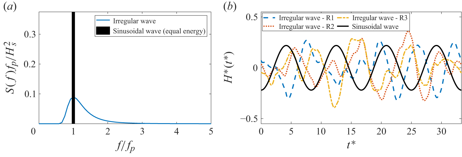
 Hs∗=0.62
 C=0.12


 Hs∗
 H0∗
 C
 w
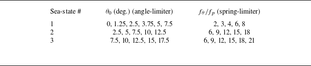

 fθ/fh=9
 θ0=7.5

 fθ/fh=9
 fθ/fh=9
 θ0=7.5∘

 C¯T
 fθ/fh
 H0∗=0.31,StC=0.12
 H0∗=1.56,StC=0.04
 H0∗=2.75,StC=0.03
 fθ/fh=9

 fθ/fh
 H0∗=1.56,StC=0.04


 x
 fθ/fh=9
 θ0=7.5∘

 ΛLEV
 fθ/fh=9
 θ0=7.5∘
 CT
 ΛLEV

 H∗
 θ
 sin(αeff)
 sin(θ)
 fθ/fh=9
 θ0=7.5

 w=2fho/U∞
 w=2h˙rms/(πU∞)


 t∗=


 Open access

