


Techniques such as two-dimensional imaging remain limited in their ability to effectively illustrate the complex three-dimensional relationships present in structural heart disease.Reference Schmauss, Schmitz and Bigdeli 1 , Reference Schmauss, Gerber and Sodian 2 These three-dimensional printed anatomical models are created by a process where a three-dimensional digital surface is created on the basis of medical images and then sent to a three-dimensional printer. It represents the next step in advanced image processing. It can serve as a means to improve our understanding of the many forms of structural heart disease and to plan surgical repair. The technology can thus be used to enhance the level of care provided to the growing number of patients with CHD. Several reports have been published reporting the feasibility and usefulness of rapid prototyping technology to understand the anatomy and pathology of CHD with rigid three-dimensional models.Reference Kim, Hansgen, Wink, Quaife and Carroll 3 – Reference Noecker, Chen and Zhou 10 Shiraishi et alReference Shiraishi, Yamagishi, Hamaoka, Fukuzawa and Yagihara 11 reported successful simulation of the Norwood procedure in a flexible rubber-like urethane model of the heart in a 4-day-old child with hypoplastic left heart syndrome.
The aim of this study was to assess the utility of three-dimensional printed models in assisting with preoperative planning for children with a univentricular heart and abnormal systemic or pulmonary venous drainage. We include three children who had undergone either a bidirectional cavopulmonary or a total cavopulmonary circulation creation in this study.
Methods
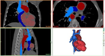
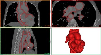
Consent was obtained from the ethics committee of Our Lady’s Hospital for Sick Children to undertake the study. Parents of each child also gave informed consent. Data to generate the models were derived from CT images, which were already performed in the three patients for clinical indications. These images were saved in Digital Imaging and Communications in Medicine format and imported to dedicated post-processing software (Mimics® Innovation Suite; Materialise NV, Leuven, Belgium). The data were processed to reduce imaging noise and isolate the anatomy of interest. The blood pool of the region of interest was segmented from the medical images via thresholding and interactive editing operations (Fig 1). Subsequently, a three-dimensional computer model was rendered for visualisation (Fig 2). 3-matic® software was then used to smooth the surface of the blood pool, create a wall thickness, make visualisation cuts or windows, and ensure that the model was suitable for three-dimensional printing. The computer model was then saved in the Surface Tesselation Language file format and sent to the three-dimensional printer for manufacture. Several three-dimensional printing technologies are available, including stereolithography, laser sintering, fused deposition modelling, among others. They have in common that the parts are built layer by layer. The process by which each layer is created differs among technologies. Each technology offers its specific material options, with their own strengths and limitations in terms of durability, flexibility, transparency, colour, etc. In the present study, the HeartPrint® flex process (Materialise NV) was selected to create translucent models with compliance in the same range as arterial tissues.
Segmentation and computer model of the blood volume in Mimics® software. Data from Case 1.

Final model and its contours on the medical images in Mimics® software. Data from Case 1.

Results
Case 1
An 11-year-old boy had a three-dimensional printed model created to assist with planning of a Fontan revision, after right-sided arteriovenous malformations led to significant desaturation. His original cardiac diagnoses were congenital heart block, left atrial isomerism/polysplenia, interruption of the inferior caval vein with azygous continuation to a single right superior caval vein, partial anomalous pulmonary venous drainage to the right atrium, superior–inferior arrangement of the ventricles, atrioventricular and ventriculoarterial discordance with abnormally related great vessels, and hypoplastic right-sided ventricle. There was a right-sided aortic arch.
He underwent a modified left Blalock–Thomas–Taussig shunt, interruption of the main pulmonary artery, atrial septectomy, and insertion of VVI epicardial pacemaker at 21 days of age. At 12 months of age, he underwent a Kawashima procedure and insertion of a DDD epicardial pacemaker. At 3 years of age, he underwent redirection of his hepatic venous drainage to the pulmonary arteries. Over the years following his Fontan procedure, he became progressively more cyanosed with resting transcutaneous oxygen saturations of 70–78% in room air.
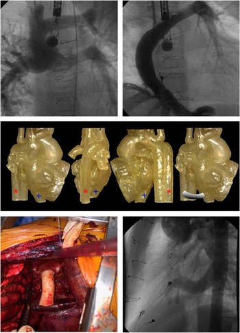
At 9 years of age, he underwent a cardiac catheterisation procedure, which identified extensive pulmonary arteriovenous malformations throughout the right lung (Fig 3a). It also showed that the hepatic venous drainage via the Fontan conduit was preferentially streaming into the left pulmonary artery (Fig 3b). This was attributed to minimal hepatic venous factor reaching the right lung, predisposing to the development of arteriovenous malformations. The mean pulmonary arterial pressures measured 12 mmHg, and the fenestration was closed during catheterisation. In the days following fenestration closure, his oxygen saturations rose to 83% in room air; however, when the patient returned to the outpatient clinic 3 months later, his saturations were found to have dropped (74–79%).
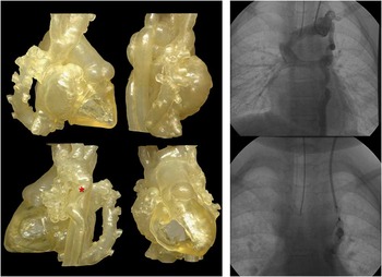
( a ) Angiography of the pulmonary arteries demonstrating extensive pulmonary arteriovenous malformations throughout the right lung. ( b ) Angiography of the Fontan conduit demonstrating how hepatic venous drainage via the Fontan conduit was preferentially streaming into the left pulmonary artery. ( c ) Three-dimensional printed model in the anteroposterior, lateral, and posterior views demonstrating total cavopulmonary connection favouring the left pulmonary artery and the right pulmonary artery with the absence of “hepatic factor”. Note the azygous vein (red asterisk) and the hepatic veins (blue cross). Preoperative planning of interposition graft between the hepatic veins and the azygous vein. ( d ) Placement of 8-cm×16-mm interposition graft between the extracardiac conduit and the azygous vein.

At this time, a cardiac CT was performed to allow better visualisation of the relationship of the Fontan conduit with the branch pulmonary arteries. A three-dimensional printed model fashioned from the CT data (Fig 3c) clearly demonstrated how the extracardiac Fontan Gortex tube was preferentially directed towards the left pulmonary artery with streaming of blood into the left pulmonary artery.
The three-dimensional printed model allowed the cardiothoracic surgical team to appreciate the three-dimensional relationship of all the cardiac structures, both native and artificial, and to devise a plan to interpose a graft between the hepatic veins and the azygous connection as published previously by McElhinney et al.Reference McElhinney, Marx, Marshall, Mayer and del Nido 12 The feasibility of such an operation was considered, and the relevant distance between the two structures was appreciated (Fig 3c), allowing accurate estimation of what type and size of graft would be required. He underwent placement of a 8-cm×16-mm Goretex tube interposition graft between the azygous vein and the hepatic veins (Fig 3d) via a right lateral thoracotomy with extracorporeal membrane oxygenation on stand-by. A 3′0 plegetted horizontal mattress suture was placed in the extracardiac conduit 2 cm above the anastomosis to promote flow through the hepatic vein diversion conduit.
Postoperatively, the patient required oxygen to maintain transcutaneous oxygen saturation in the low 70s. Cardiac catheterisation and angiography were undertaken to confirm patency of the conduit (Fig 3e). The mean cavopulmonary pressure was 14 mmHg. The reduced oxygen saturation was secondary to atelectasis in both lower lobes. On most recent follow-up, the oxygen saturation measured 80–83%.
Case 2
A 7-year-old boy had a three-dimensional printed model created to assist with planning of Fontan completion, complicated by mixed hepatic venous drainage. His original cardiac diagnoses were right atrial isomerism/asplenia, dextrocardia, bilateral superior caval veins, a left ventricular dominant atrioventricular septal defect, complete transposition of the great arteries, and severe pulmonary stenosis. He had an uninterrupted inferior caval vein to the right-sided atrium but mixed hepatic venous drainage. The inferior caval vein drained to the right-sided atrium, and there appeared to be separate left-sided hepatic veins draining to the left-sided atrium. There was total anomalous pulmonary venous drainage to the left superior caval vein, which was unobstructed. He underwent trancatheter stenting of his patent ductus arteriosus at 5 months of age, as he developed progressive desaturation secondary to severe pulmonary stenosis. He had a bidirectional Glenn anastomosis at 9 months of age.
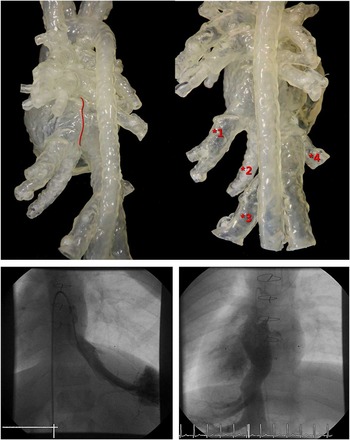
A diagnostic cardiac catheterisation and cardiac CT were undertaken at 6 years of age to delineate the systemic venous drainage before completion of the total cavoplmonary connection (Fig 4). A three-dimensional printed model (Fig 4) was generated to provide improved three-dimensional understanding of the course of the hepatic veins in relation to the surrounding cardiac structures and to plan a pathway to incorporate the hepatic veins into the total cavopulmonary conduit to the pulmonary arteries. The three-dimensional printed model highlighted the significant distance between the right-sided inferior caval vein – along with two draining hepatic veins – and the two separate left-sided draining hepatic veins. The significant distance between the left-sided and the right-sided draining veins and the intervening presence of the atrial septum between the veins ruled out the possibility of a lateral tunnel approach. The acute medial angulation of the left-sided veins away from the pulmonary arteries was believed to make fashioning two conduits or a single conduit impossible. In addition the pulmonary venous relationship to the pulmonary arteries raised concern for potential pulmonary venous obstruction within the plane of an attempted conduit placement. After extensive discussion, the consensus was for medical management given the numerous complicating factors.
( a ) Angiography of two left hepatic veins draining into the left-sided atrium. ( b ) Three-dimensional print model demonstrating multiple sites of hepatic venous drainage to the atrium in a child with heterotaxy syndrome status after bidirectional Glenn. The relationship of the inferior caval vein with multiple entry points of the mixed hepatic venous drainage allowed the surgeon to preoperatively plan the course for conduit in total cavopulmonary connection. ( c ) The relationship of the atrial septum with multiple entry points of the hepatic veins and the inferior caval vein.

Case 3
A 4-year-old girl with Kabuki syndrome was born with hypoplastic left heart syndrome – mitral and aortic stenosis – and right-sided infradiaphragmatic anomalous pulmonary venous drainage to the inferior caval vein. There was no evidence of right lung hypoplasia or right pulmonary artery hypoplasia. She had previously undergone modified Norwood procedure with a Blalock–Taussig shunt at 14 days of age and a bidirectional Glenn procedure at 4 months of age. Over the following 3–4 years, she developed progressive desaturation, with baseline transcutaneous oxygen saturation of 70% dropping to 60% with exercise.
A cardiac CT was performed to provide more information on the spatial relationship of this anomalous vein to the potential position of the Fontan conduit. A three-dimensional printed model (Fig 5) was subsequently created demonstrating a very large anomalous scimitar vein draining the right lung and inserting under the diaphragm into the inferior caval vein, directly adjacent to the insertion of the hepatic veins. The length and size of the scimitar vein, as well as its point of insertion, suggested that baffling of the inferior caval vein to the atrium would be a challenge. The position of the scimitar vein was directly in the plane of the potential location of the Fontan conduit, and thus it was elected to defer surgical intervention at this time. The three-dimensional print model, however, demonstrated a veno-venous collateral draining to the innominate vein. This vessel was well seen on cardiac catheterisation (Fig 5). This vessel was occluded with an Amplatzer occluder device, resulting in an increase in saturation to 82–86% (Fig 5).
Three-dimensional print model demonstrating a patient with hypoplastic left heart syndrome s/p Norwood, s/p Glenn with “scimitar” form of systemic partial anomalous venous drainage to the inferior caval vein. Cardiac catheterisation demonstrating the veno-venous collaterals draining to the innominate vein (red asterisk) before and after occlusion with Amplatzer occlusion device.

Discussion
The use of three-dimensional printed anatomical models of the heart to better understand the anatomy of complex CHD and also to plan surgical repair is feasible and useful. This study demonstrated that three-dimensional printed models were invaluable in the preoperative planning for three patients with complex univentricular hearts and venous drainage abnormalities. In fact the most useful information gleaned from the three-dimensional printed models in two of our patients was that surgical intervention might have caused significant complications. Schievano et alReference Schievano, Migliavacca and Coats 9 similarly found that cardiologists were better able to predict who would not be suitable candidates for percutaneous pulmonary valve replacement on the basis of three-dimensional models compared with MRI. If not operating the patient is deemed the best approach, the model may also be used to facilitate communicating the surgical decision to the patient and family. Others have reported the use of a patient-specific three-dimensional cardiac model to plan surgical repair of transposition of the great arteries, ventricular septal defect, and pulmonary stenosis.Reference Valverde, Gomez and Gonzalez 13 The additional information gained from the model directed the team to choose and plan a Nikaidoh rather than a Rastelli procedure.
Obtaining and using a three-dimensional model of a patient’s heart ensure that the surgeon is not naïve to the patient’s specific individual anatomy as it currently stands, in a way that cannot be appreciated on a screen. They can more clearly visualise and experience in a tactile manner the three-dimensional relationships of each structure to another in real scale. They can accurately calculate the size of structures and relevant distances between structures, which would allow preoperative selection of grafts and other materials in advance. In the case of patient one, the surgeon was able to accurately predict the type and size of graft required for a hepatic vein-to-azygous vein connection. Models may be brought into the operating theatre to facilitate orientation, especially if the model allows a view not achievable intraoperatively because of other surrounding structures. They may also offer intracardiac views that are not obtainable intraoperatively without excising the myocardium. Mottl-Link et alReference Mottl-Link, Hubler and Kuhne 6 and Ngan et alReference Ngan, Rebeyka and Ross 7 found that three-dimensional physical models greatly assisted visualisation and orientation in the operating room for complex CHD surgery. The surgical team found that the model assisted in planning the pathway for the hepatic vein-to-azygous conduit.
At present, three-dimensional printed heart models are also being increasingly used to plan and practice catheter-based interventions in CHD patients. Olivieri et alReference Olivieri, Krieger, Chen, Kim and Kanter 14 described successful stent angioplasty of pulmonary venous baffle obstruction during a Mustard repair for d-transposition great arteries, after a patient-specific three-dimensional printed cardiac model was used to test multiple catheter approaches and stent deployment. Dankowski et alReference Dankowski, Baszko and Sutherland 15 reported the use of a three-dimensional printed cardiac model to plan a percutaneous mitral annuloplasty with the Mitralign percutaneous annuloplasty system. Guidewires and catheters were placed within the model to direct selection of guidewire size and to assess the ability to route the catheter under the mitral annulus, between the papillary muscles. This enabled appropriate catheter position for delivery of the wires and surgical pledgets across the valve. A three-dimensional cardiac model has also been used to simulate endovascular stenting of a hypoplastic arch under fluoroscopic guidance.Reference Valverde, Gomez and Coserria 16 The assessment of optimal stent position, size, and length on the model was found to be useful for the actual intervention in the patient.
A disadvantage in this study was that the models used were not made from material suitable for “practice surgery”. Surgery has been performed on models made from flexible urethane; however, inadequacies in this field still exist with regard to flexibility, durability, and texture of the models differing from real cardiac tissue.Reference Shiraishi, Yamagishi, Hamaoka, Fukuzawa and Yagihara 11 Valverde et alReference Valverde, Gomez and Coserria 16 directly compared a rigid and a flexible polymer for creating a hypoplastic aortic arch, which were used to perform endovascular stenting. They report that the flexible model, unlike the conventional rigid model, allowed vessel expansion due to the elastic properties of its polylactic acid material. In the search to find a material to create more compliant vascular phantoms suitable for in vitro experiments and device testing, Biglino et alReference Biglino, Verschueren, Zegels, Taylor and Schievano 17 also report that TangoPlus – a commercially available rubber-like material – is suitable for manufacturing vascular phantoms, with distensibility values similar to arteries, including the ascending and descending aortas. These models are usually derived in end diastole or averaged over the cardiac cycle. Other limitations include the need to cut the model when viewing intracardiac relationships and the difficulty in imaging the valvar structures of the heart.
Perhaps the most exciting progression in the search for the perfect substrate material has been the amalgamation of tissue engineering with three-dimensional printing. Living tissues and other biocompatible materials are being three-dimensional “bioprinted”, with the hope of making advancements in the field of regenerative medicine; however, current three-dimensional bioprinting technologies need to be improved with respect to the mechanical strength and integrity in the manufactured constructs, and furthermore a better understanding of the tissue/organ microenvironment is imperative to improve three-dimensional bioprinting.Reference Zhang and Zhang 18
A further advancement is the use of three-dimensional printed cardiac models to study the functional properties and effects of certain structural heart lesions. Maragiannis et alReference Maragiannis, Jackson, Igo, Chang, Zoghbi and Little 19 printed three-dimensional aortic roots with severe degenerative aortic stenosis, from clinical CT imaging data. Each model was coupled to a pulsatile flow imaging circuit, and pressures proximal and distal to the aortic valve were measured with pressure catheters. Ultrasonic flow transducers assessed transvalvular stroke volume flow. This group concluded that functional characteristics were accurately replicated with the model, when compared with echocardiographic and catheter data already acquired on the patient. Biglino et al,Reference Biglino, Verschueren, Zegels, Taylor and Schievano 17 for the purpose of distensibility testing, successfully inserted a mock circulatory loop onto a three-dimensional printed infant hypoplastic aorta. They replicated pressures in the physiological range for a patient with hypoplastic left heart syndrome, which the model was able to withstand.
Our three patients had their three-dimensional printed cardiac models created using CT images. Alternatively, MRI data can be used, and several groups have reported success with this approach, with the creation of models of similar quality and high structural accuracy.Reference Mottl-Link, Hubler and Kuhne 6 , Reference Schievano, Migliavacca and Coats 9 , Reference Valverde, Gomez and Gonzalez 13 , Reference Valverde, Gomez and Coserria 16 , Reference Biglino, Verschueren, Zegels, Taylor and Schievano 17 More recently, Olivieri et alReference Olivieri, Krieger, Loke, Nath, Kim and Sable 20 have reported that three-dimensional printing of intracardiac defects derived from three-dimensional echocardiographic images is feasible and relatively accurate. The major advantage of using MRI and echocardiographic imaging over CT to create three-dimensional printed models is the elimination of radiation exposure to the patient; furthermore, in the young infant and child, in order to achieve good CT and MRI, sedative or general anaesthetic agents are usually administered. With echocardicardiography, it may be possible to perform an adequate study without this, thus further reducing risk to the patient.
In conclusion, we found that three-dimensional printed models of the heart were invaluable in the preoperative planning for three patients with complex univentricular circulations and venous drainage abnormalities. There is still a lot of work going on to find the perfect material to more accurately represent cardiac and vasculature tissues, which will further improve the accuracy of functional testing and simulated procedures. Bioprinting offers many possibilities in the field of regenerative medicine. MRI and more recently echocardiographic imaging data may be considered as an alternative for CT imaging to reduce risk in the appropriate patient groups.
Acknowledgements
The authors are very grateful to Andrew Pendred for his extensive work on the project and assistance in audiovisual input. The authors are also very grateful to Daniel Daryaie, Julie Maes, and Patricia Lopes at Materialise NV, Leuven, Belgium, for all their assistance in generating the three-dimensional printed models and with the description of the manufacturing process. We are grateful to our cardiology and surgical staff colleagues at Our Lady’s Hospital for Sick Children, Crumlin.
Financial Support
This research was financed by a grant from the National Children’s Research Centre in Our Lady’s Children’s Hospital Crumlin.
Conflicts of Interest
None.
Ethical Standards
The authors assert that all procedures contributing to this work comply with the ethical standards of Crumlin Children’s Hospital and with the Helsinki Declaration of 1975, as revised in 2008 and has been approved by the Institutional Committee Crumlin Children’s Hospital.