I. INTRODUCTION
It is well known that intermetallic compounds have good soft magnetic properties. FeCo alloys based on intermetallic compounds exhibit high saturation magnetisation (2.45 T) and high Curie temperatures (920–985 °C). In particular, the equiatomic composition exhibits the highest permeability and zero magnetocrystalline anisotropy. Reference Sundar and Deevi1 However, the ordered Fe50Co alloy is extremely brittle and its workability is therefore typically improved by the addition of alloying elements such as 2%wt vanadium; as in Permendur or FeCo–2V alloy. Reference Clegg and Buckely2 Such alloying elements lead to the formation of precipitates; improving the mechanical properties yet leading to a deterioration of the magnetic properties. The coercivity in particular is affected by the presence of microstructural defects, such as grain boundaries and dislocations. Reference Yu, Basu, Ren, Zhang, Parvizi-Majidi, Unruh and Xiao3 Equiatomic-iron cobalt alloy is primarily used in applications where the reduction of weight or volume of material is of primary importance. Reference Clegg and Buckely2 As a result there is a continuous interest in improving the properties of these alloys. The disordered state of this alloy exhibits higher yield strength than the ordered state combined with a change in fracture mode from intergranular to transgranular cleavage. Reference George, Gubbi, Baker and Robertson4,Reference Zhao and Baker5 Zhao et al. Reference Zhao, Baker and George6 investigated the effect of constitutional and thermal disorder on the ductility of ordered and disordered FeCo alloys; and concluded from the practical results that the partial disorder at grain boundaries is required to achieve some ductility for an ordered FeCo alloy. Since a dispersion of nanosize reinforcement in FeCo alloy may lead to partial disorder at the grain boundaries, an improvement in ductility may therefore be expected.
Bowen et al. Reference Bowen and Doe7 have shown that the mechanical properties, tensile strength, and ductility of composite materials are strongly affected by the size of the reinforcement, with tensile strength increasing with reduction in reinforcement size. This strategy for improving mechanical properties can be broadly applied to many light-weight alloys. However, there have only been a limited number of studies of iron cobalt alloys with the addition of very fine reinforcement. Composite materials have advantages in comparison to their base alloys, such as a superior creep resistance, and the final properties of the material can be tailored through appropriate selection of the type and volume fraction of reinforcement. Reference Kumar, Viola, Reece, Hall and Evans8 The effects of nanoscale reinforcements on the tensile properties of FeCo alloys have not previously been reported.
Carbon nanotubes (CNTs) possess outstanding properties such as an average Young's modulus of 1.8 TPa. This combined with their high aspect ratio with lengths of 1.17–5.1 µm and outer diameters 5.6–8.4 nm, low density, and flexibility make them good candidates for reinforcement in nanoscale fiber composite materials. Reference Treacy, Ebbesen and Gibson9,Reference Chen, Xia, Peng, Li and Xie10 The main aim in adding CNTs is to increase the tensile strength and elastic modulus of the composite. Reference Bakshi, Lahiri and Agarwal11 However, dispersing CNTs in a metal matrix can be a challenging, due to the large difference in surface tension, which leads to poor wettability between the reinforcement and matrix alloy. Reference Kong, Zhang, Xiong, Liu, Huang, Sun, Tu and Chen12 Ball milling has been shown to produce good dispersion of CNTs in metal matrix composites. Reference Bakshi, Lahiri and Agarwal11 Mani et al. Reference Mani, Viola, Reece, Evance and Hall13 have found that even surface modification of CNTs by electroless plating followed by ultrasonic agitation did not produce a uniform dispersion of reinforcement without ball milling.
Spark plasma sintering (SPS) is an advanced sintering method for the rapid consolidation of powders. Through the application of high pressures and electric currents, rapid heating rates (up to 1000 °C/min), and short sintering times (3–5 min), can be used to produce fully dense material. Reference Song, Liu and Zhang14 This method has been explored in the fabrication of CNT–metal matrix composites, due to its ability to preserve nanoscale features. Reference Bakshi, Lahiri and Agarwal11,Reference Saheb, Iqbal, Khalil, Hakeem, Al Aqeeli, Laoui, Al-Qutub and Kirchner15 During SPS, the measured temperature is used to modulate the electric current to follow a set heating curve. However, temperature is measured using either thermocouples or pyrometers which are focused on the punches and dies close to the sample, rather than on the sample itself. The temperature of the sample can therefore be significantly over or underestimated if large temperature gradients exist. More accurate ways to calibrate SPS temperature are therefore of great interest. Recently, an accurate calibration of SPS temperature has been performed Reference Kumar, Viola, Hall, Grasso and Reece16 using the phase transformation which occurs in soft magnetic FeCo alloy at the Curie point. The phase transformation alters the thermal and electrical conductivity of the alloy; leading to an anomalous pulse in the current–temperature curve. At this point the actual temperature of the sample (the Curie temperature) is known and can be compared with the corresponding thermocouple or pyrometer reading.
The objective of this study was to evaluate the effects of CNT addition on the mechanical and DC magnetic properties of Fe50Co composites prepared by SPS.
II. EXPERIMENTAL WORK
The binary gas atomised Fe50Co alloy powder was supplied by Sandvik Osprey Powder Group. A scanning electron microscope with energy dispersive X-ray spectrometer (EDS) attachment of Oxford instrument was used to study the morphology and composition of the powders. A Malvern Mastersizer 3000 (Malvern Instruments, Worcestershire, United Kingdom) was used to measure the particles size distribution of the Fe50Co powder.
Multiwalled carbon nanotubes (MWCNTs) were provided by Haydale Ltd., which were functionalized using a plasma treatment to incorporate a covalently bonded oxide group to the surface. The key advantage of the functionalization process is to improve the CNT dispersion in the solvent during colloidal processes by reducing the van-der-Waals forces between the nanotubes. Reference Hirsch and Vostrowsky17,Reference Bahr, Yang, Kosynkin, Bronikowski, Smalley and Tour18 Two different methods were used to mix iron cobalt alloy powder with functionalized multiwalled carbon nanotubes. The first method (A) involved the dry mixing of the reinforcement with 20 g of binary Fe50Co alloy powder for volume fractions of 0.5–4.5 vol%, followed by milling the mixture in a ball pestle impact grinder at ball powder ratio (BPR) (1:1) for 1 h. The second method (B) involved the wet mixing of multiwalled carbon nanotubes with Fe50Co powder in dimethyformamide, DMF, for volume fractions of 0.5–3 vol%. DMF is a commonly used solvent for dispersing carbon nanotubes. Reference Ham, Choi and Chung19 The suspension of carbon nanotubes in DMF was stirred under ultrasonic agitation for 60 min followed by the addition of 20 g of alloy to each suspension. The resulting slurry was sonicated for 30 min. The slurry was dried on a hot plate at the evaporation temperature for DMF (150 °C) overnight. The dried mixture was then milled in the ball pestle impact grinder at BPR (1:1) for 1 h.
The Fe50Co alloy and composite powder mixtures were consolidated in a graphite die using a SPS furnace (HPD 25/1 FCT, FCT Systeme GmBH, Rauenstein, Germany). All of the samples were heated to the sintering temperature at a constant rate of 50 °C/min under a vacuum of 1 hPa. An initial pressure of 7 MPa was applied from room temperature to 400 °C; followed by an increase to 80 MPa pressure and simultaneous heating to 900 °C for a 3 min dwell. Reference Mani, Viola, Reece, Hall and Evans20 Samples were left to cool in the furnace and extracted from the die using a manual hydraulic press. The Archimedes' immersion method in water was then used to measure the density of the compacts. The theoretical densities of the composites were calculated using the rule of mixtures. The theoretical densities for the CNT and FeCo powders were taken as 1.4 and 8.174 g/cm3, respectively for calculations.
Cross-sections of the sintered materials were ground and polished with different grade abrasive discs followed by etching using 10% Nital for 30 s. Optical microscopy and scanning electron microscopy (SEM) were used to analyze the microstructural features. To evaluate the magnetic properties, samples with a rectangular cross section (24 × 5 mm) were cut from 30 mm diameter sintered disks using an electron discharge machining (EDM) cutting machine. Samples were ground using silicon carbide papers to remove the scratches from cutting. An automatic universal measurement system was used to evaluate the quasi DC magnetic response for samples by changing the magnetic field up to 25 kA/m. Reference Anderson21 Hardness measurements for both the matrix alloy and composites were performed at five different locations using a Vickers hardness tester with an applied load of 30 g for 4 s. Tensile tests were performed on 3 samples cut from 30 mm diameter monolithic alloy and composites disks using EDM. The cut samples were ground using silicon carbide to remove any crack initiation sites produced by the cutting. The tensile sample dimensions were (11 × 3 × 1.25 mm). Reference George22 The tensile mechanical properties of the materials were measured using a Shimadzu testing machine (Shimadzu Corporation, Kyoto, Japan) with a cross head speed of 2 mm/min.
III. RESULTS AND DISCUSSION
A. Characterization of the starting powders and sintered materials
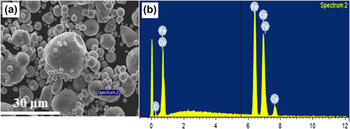
An SEM image of the Fe50Co alloy powder is shown in Fig. 1. Spherical particles with a wide size distribution are evident; Dv (10) 9.79 μm, Dv (50) 23.4 μm, and Dv (90) 54.0 μm.
(a) SEM image and (b) EDS spectrum of as-received FeCo alloy powder.

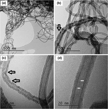
TEM images of plasma-treated CNTs are presented in (Fig. 2), the arrows identify the defects which may be subdivided into dimensional and structural defects. Most of the CNTs are tangled with each other, which impedes their dispersion. The nonuniformity in the graphene layers, discontinuity on the inside of the fibers, and defects on the outer surfaces suggest that the defects may not only be produced during fabrication but also by the functionalization processes. Amorphous carbon was observed on the surface of the fibers. These imperfections are preferred sites for chemical reaction. Some dark areas were observed on the CNTs which are probably metal inclusions occurring from the reaction with the metallic catalyst used during their fabrication. Reference Hirsch and Vostrowsky17 The measured dimensions of the CNTs exhibit a mean outer diameter of around 10.45 nm, while the inner diameter is around 4.29 nm. This corresponds to 34 concentric shells of carbon sheets in some cases, but for most CNTs, it was typically about 10. Caps were observed at the ends of some of the CNTs, while some tubes showed open ends. This opening of the hemispherical cap is due to oxidation during the functionalization step.
Transmission electron micrographs of plasma-treated CNTs; the arrows highlight defects.

An X-ray diffraction (XRD) pattern of the as-received CNTs, generated using a copper anode, is shown in Fig. 3. The main peaks for carbon nanotubes were observed at 2θ values of ∼26° and ∼43° and are in good agreement with the pattern previously reported in Ref. Reference Mani, Viola, Reece, Evance and Hall13. The d 002 calculated using the Bragg equation (λ = 2d sin θ) is 0.3445 nm, which is consistent with spacing for graphite of 0.3348–0.3360 nm (5% experimental error). A broadening of the peak at ∼26° could be observed, and is likely due to the presence of oxides introduced to the CNTs during functionalization process; with the variation in d spacing due to the incorporation of oxygen between the lattice planes. Broadening could also be due to contributions from the amorphous regions of the CNTs.
XRD pattern of as-received CNTs, the main diffraction planes are labeled.

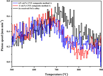
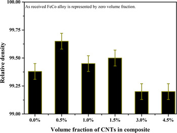
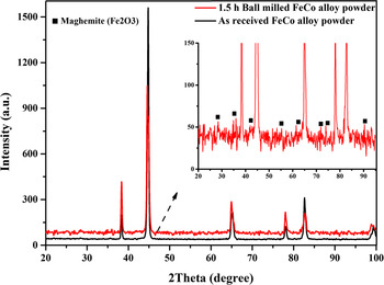
The densification behavior of as-received monolithic FeCo alloy and composite were different as shown in Fig. 4. The volume fraction of reinforcement affected the densification behavior. The composite materials densified at lower temperatures compared to as-received alloy, which could be due to the influence of CNTs on the densification mechanism. In addition, the ball milling step decreased the particle size in the composite which increased the surface area between reactants; leading to faster densification kinetics through improved mass transport by diffusion. Reference Locci, Orru, Cao and Munir23,Reference Thomson, Jiang, Ritchie and Mukherjee24 The densities of the composites containing up to 1.5 vol% CNT were higher as compared to the monolithic Fe50Co alloy as shown in Fig. 5. The highest density was achieved for the 0.5 vol% CNTs composites; while the density dropped sharply at higher volume fractions. This is due to the increased agglomeration of the CNTs, which induces porosity in the composite material. Figure 6 shows a comparison between monolithic FeCo alloy powders before and after ball milling processes. The peaks after 1.5 h ball in air atmosphere are identical to the maghemite phase. The powder is heated up during ball milling, leading to the formation of oxide layer which deteriorates densification during sintering because it forms a diffusion barrier during sintering.
Shrinkage sintering curve, for the as-received FeCo alloy in comparison to the 1 and 4.5 vol% CNT composite materials prepared using method A.

Variation of relative density of SPS sintered composite materials fabricated using method A against volume fraction of CNTs (%) compared to monolithic FeCo alloy.

XRD shows oxidation of FeCo alloy due to ball milling in air atmosphere.

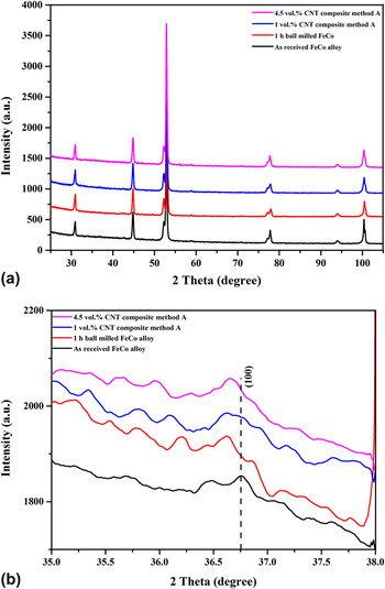
Figures 7(a) and 7(b) show slow scan XRD patterns (Co Kα) for the sintered Fe50Co as-received, ball milled, and composite forms. The enlarged pattern of the (100) peak [Fig. 7(b)] was used to observe the ordering of the Fe50Co alloy, which was scanned in the range of the expected superlattice line. Reference George, Gubbi, Baker and Robertson4 The pattern shows that the addition of 1 vol% CNTs with ball milling produced a reduction in the antiphase domain size for the ordered crystalline phase. The crystallite domain sizes were calculated using the Scherrer equation of the (100) peak [Fig. 7(b)] as 45.75, 28.10, and 34.32 nm for as-received Fe50Co alloy, 1 vol% CNT, and 4.5 vol% CNT, respectively. The composite with a higher volume fraction of CNTs displayed an increase in crystallite size, yet a high intensity of ordering was observed in the XRD patterns. As such, it appears that an increase in the volume fraction of CNTs produces an increase in the volume fraction of ordering as compared to the monolithic alloy and low volume fraction composites. Strains are classified to uniform strain and nonuniform strain, the former lead to shifting peaks of X-ray reflection to lower angles, while the latter lead to broadening and reduce the intensity. Reference Cullity25 Ball milling processes can induce stresses in powder; however, the intensity of ball milling was very low as the process was performed for BPR 1:1 for 1 h to disperse the reinforcement in the base alloy. Residual stress may be released during sintering at high temperature. This suggests that the effects of strain on broadening X-ray reflection are minimal, as the recovery reduces the magnitude of the residual stress and recrystallization completely eliminates the residual stress leading to the maximum sharpness in diffraction line. Reference Cullity25
XRD patterns (a) slow scan for sintered FeCo as-received alloy, 1 h ball milled FeCo alloy, 1 vol% CNT composite, and 4.5 vol% CNT composite; (b) (100) superlattice peak for displayed material.

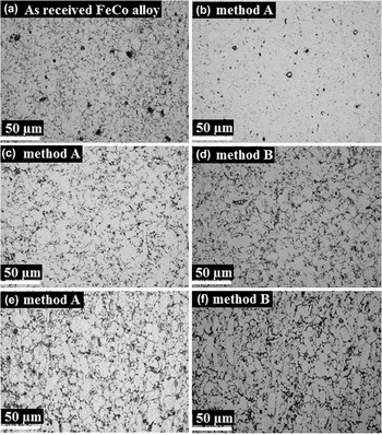
The optical micrographs for both the Fe50Co alloy and the composites are shown in Fig. 8. A very fine microstructure was observed for the 0.5 vol% CNT composite, which reflects the role of CNTs in refining the microstructure. However, this behavior is different at higher volume fractions of CNTs due to the segregation of carbon nanotubes to the grain boundaries; which cause an increase in the thickness of the grain boundaries of the composite materials compared to the monolithic alloy. This agglomeration causes poor densification at higher volume fractions. Pores and elongated grains were observed at high volume fractions. The ball milling process changes the shape of the powder particles; and as a result, an elongated grain structure is observed after sintering. This structure becomes more evident due to the increasing fraction of agglomeration and the poor densification at high volume fraction of CNT. No difference can be observed in the microstructure between the two methods used to prepare the composites.
Optical microstructure of: (a) FeCo alloy; images (b), (c), and (e) are 0.5 vol%, 1 vol%, and 3 vol% CNT composite, respectively, prepared by method A. Images (d) and (f) are 1 vol% and 3 vol% CNT composite, respectively, prepared by method B.

B. Magnetic and mechanical properties
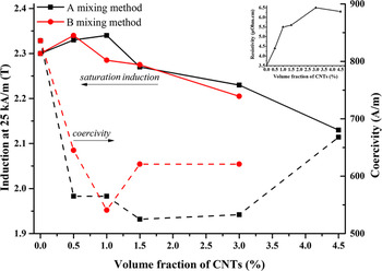
The magnetic properties of the Fe50Co alloy and composite materials fabricated following mixing methods A and B are summarized in Fig. 9. It is clear that the saturation induction is highly dependent on sample density; with the saturation induction trend closely following that of the density trend (Fig. 5) with increasing volume fraction of CNTs. The highest saturation induction was achieved in the composite material at 1 vol% CNTs, consistent with it having a high density. With an increased volume fraction of CNTs, a drop in saturation is seen due to the agglomeration of the reinforcement as observed in (Fig. 8) and the subsequent of that drops in density.
Effect of volume fraction of CNTs on: saturation induction; coercivity of (Fe50Co)–CNT composites fabricated by two different dispersion methods followed by SPS. The monolithic alloy is represented as 0 vol% CNT. The inset curve shows the change in resistivity with increasing volume fraction of CNTs for composites prepared using method A.

A drop in coercivity was observed in the composites produced by both fabrication methods in comparison to the monolithic Fe50Co alloy. Coercivity is typically inversely proportional to the grain size; however, the results indicate a decrease in coercivity with decreasing grain size. Previous models in Ref. Reference Alben, Becker and Chi26 and Reference Herzer27 have explained this behavior in terms of the anisotropy energy. For a very small grain size (D) < 100 nm, the ferromagnetic exchange length will often be larger than the grain size (D). The exchange length in a soft magnetic alloy is calculated by using the following equation:
 $${L_{{\rm{ex}}}} = {\left( {{A \mathord{\left/ {\vphantom {A {{K_1}}}} \right. \kern-\nulldelimiterspace} {{K_1}}}} \right)^{{{ - 1} \mathord{\left/ {\vphantom {{ - 1} 2}} \right. \kern-\nulldelimiterspace} 2}}}\quad .$$
Following Eq. (1) and using exchange constant A = 1.7 × 10⁻¹¹ J/m and magnetic anisotropic constant K 1 = 8 kJ/m3 for calculation, the exchange length in Fe50Co alloy, Reference Couderchon and Tiers28 giving L ex = 46 nm, which is in value higher than the measured ordered crystallite size, meanwhile the change in coercivity with crystallite size follows Néel's model. As a consequence, the effective anisotropy energy is averaged over a number of grains and is thus reduced in magnitude. In this anomalous behavior of nanocrystalline magnetic materials, the coercivity exhibits D 6 dependence, which is in contrast to the conventional rule for polycrystalline magnetic materials, which exhibit 1/D dependence. As discussed previously, the Scherrer calculations show a crystallite size below 100 nm in the monolithic Fe50Co, which decreases further for the composite samples. This may therefore account for some of the trends seen in coercivity. However, at the highest volume fraction of CNTs the coercivity increased. It has been reported that the coercivity is directly proportional to the volume fraction of nonmagnetic inclusions. Reference Pfeifer and Radeloff29 Residual stresses produced due to the difference in the coefficient of thermal expansion between the CNTs and the monolithic Fe50Co alloy may lead to domain wall pinning, thereby increasing coercivity and creating a trade-off between coercivity decrease due to grain size and increase due to domain wall pinning as the volume fraction of reinforcement is increased.
A high resistivity is crucial for producing low loss components. Resistivity measurements of the monolithic Fe50Co alloy and CNT composites fabricated using method A are shown as an inset in Fig. 9. A slight increase in resistivity is observed from 3.5 µΩ cm for monolithic Fe50Co alloy to 5.6 µΩ cm for the composite with the highest density up to 1.5 vol% CNTs. Higher volume fractions of CNTs (3 and 4.5 vol%) further increase the resistivity of composite materials, which may be due to the increase in the level of porosity.
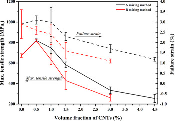
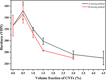
The tensile strength and the mechanical hardness of the Fe50Co alloy and composite materials prepared using the two different methods are summarized in Figs. 10 and 11, respectively. The addition of a small amount of CNTs up to 1 vol% produces an improvement in tensile strength in comparison to the base alloy. The greatest improvement is observed with the addition of 0.5 vol% CNTs. In this case, a tensile strength and Vickers hardness of 821 ± 30.77 MPa and 352 ± 15.15 VHN, respectively, were measured. The mechanisms for an improvement in the mechanical properties of composite materials include load transfer between the matrix and reinforcement, grain size refinement and dislocation strengthening mechanisms. The mechanical properties are highly correlated to the grain size of Fe50Co alloys; following the Hall–Petch relationship in both the ordered and the disordered state. Reference Duckham, Zhang, Liang, Luzin, Cammarata, Leheny, Chien and Weihs30
 $${\sigma _{\rm{y}}} = {\sigma _{\rm{i}}} + {k_y}{d^{{{ - 1} \mathord{\left/ {\vphantom {{ - 1} 2}} \right. \kern-\nulldelimiterspace} 2}}}\quad ,$$
where σy is the yield strength, d is the average grain diameter, σi is a materials constant describing the intrinsic resistance of the lattice to dislocation motion, and k y is the strengthening coefficient. The optical micrographs of the Fe50Co composites show that the addition of a low volume fraction 0.5 vol% of CNTs refines the microstructure and improves densification. As a result, an increase in tensile strength and hardness at low volume fractions is achieved. However, the mechanical properties deteriorate at higher volume fractions of reinforcement using both fabrication processes. The decrease was higher for composites produced using mixing method B. It was experimentally observed that the CNTs tended to separate as a surface layer on the powder after drying using method B, leading to more agglomeration of the CNTs and subsequently poorer densification.
Effect of volume fraction of CNTs on: tensile strength (solid lines) and failure strain (dashed lines) of (Fe50Co)–CNT composites fabricated by two different dispersion methods followed by SPS; the monolithic alloy is represented as 0 vol% CNT.

Effect of volume fraction of CNTs on hardness of (Fe50Co)–CNT composites fabricated by two different dispersion methods followed by SPS; the monolithic alloy is represented as 0 vol% CNT.

An increase in the failure strain was observed in the composites containing low volume fractions of reinforcement. EDS results for monolithic Fe50Co alloy and its composites show a deviation in the chemical composition of the composite in comparison to the monolithic Fe50Co alloy. This suggests that the CNTs lead to chemical deviations in the matrix surrounding them. It has been reported Reference Zhao, Baker and George6 that particles in Fe50Co alloy cause a chemical deviation in the matrix around them, which could lead to disorder around the inclusions and possible improvement in the ductility. Moreover, additions of small amounts of CNTs lead to the development of a very fine microstructure, and may form metal carbides as a result of the reaction with any amorphous carbon on the CNTs. This may not necessarily be detectable by XRD since the amount of carbides produced would be lower than the sensitivity of the technique. These two parameters play an important role in the improvement of ductility, as has been reported previously. Reference Kawahara31
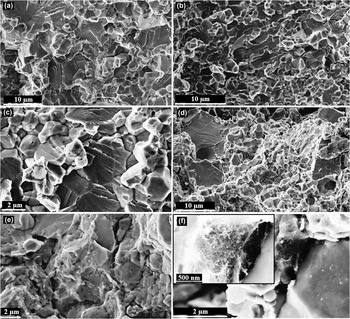
Fractographic images of the monolithic alloy and composite materials with different volume fractions of CNTs are shown in Fig. 12. Mixed modes of fracture between intergranular and transgranular were observed for both the monolithic alloy and the composite materials. Small tubular holes were observed in the fracture surface, as indicated by arrows in image (c), which are likely to be the former locations of CNTs which were extracted during fracture. Porosity can be seen to increase at high volume fractions of CNTs, as shown in image (d), while images (e) and (f) show the agglomeration of CNTs between powder particles. The high magnification inset in (f) shows the presence of CNT bundles at the boundary. These bundles would have hampered densification in the composite.
Fractographic images of materials prepared using processing route A: (a) FeCo monolithic alloy; (b) 0.5 vol% CNT composite; (c) 1 vol% CNT composite; (d) 1.5 vol% CNT composite; (e) 3 vol% CNT composite; (f) 4.5 vol% CNT composite. High magnification image inset in (f) shows CNTs bundle between powder particles boundaries.

C. Raman spectroscopy
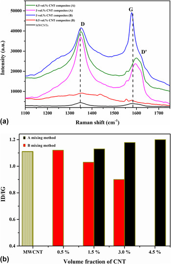
Raman spectroscopy is a nondestructive test, which is a powerful tool largely used for the characterization of various carbon-based materials for determining the degree of structural ordering or presence of contaminants. The characteristic bands in all the graphite-based materials, including MWCNT, can be classified as follows: first-order and second-order Raman spectra. Reference Antunes, Lobo, Corat, Trava-Airoldi, Martin and Veríssimo32 The former shows a tangential stretching G mode at (1500–1600 cm−1), in addition to the D mode around 1350 cm−1. There is also an exceptional band, which can only be observed in single wall carbon nanotube (SWNT), and is a radial breathing mode in the range 100–400 cm−1. Reference Antunes, Lobo, Corat, Trava-Airoldi, Martin and Veríssimo32,Reference Osswald, Havel and Gogotsi33 Furthermore, a weak shoulder band (D′) is observed around 1620 cm−1 on the right side of the G band. The second order spectra are characterized by the main peaks of (G′) at 2705 cm−1 and (D + G) at 2945 cm−1. Reference Antunes, Lobo, Corat, Trava-Airoldi, Martin and Veríssimo32 The relative intensities between the D band, which is related to structural defects, and G band, which is related to the order of the graphite structure (R = I D/I G) is widely used to evaluate the defect density of carbon nanomaterials and carbonous nanocomposite. Reference Saito, Hofmann, Dresselhaus, Jorio and Dresselhaus34,Reference Kwon, Estili, Takagi, Miyazaki and Kawasaki35 Figures 13(a) and 13(b) show the Raman results for the (Fe50Co)–CNT composites and the change in R ratio for the raw plasma-treated MWCNTs and the composites fabricated by the two different methods with respect to the volume fraction of CNTs.
(a) Raman spectra of MWCNTs and FeCo alloy composites; (b) intensity ratio (R = I D/I G) of composite fabricated by the two methods.

A split in the G band was observed, which demonstrates that the integrity of CNTs is maintained throughout the fabrication process, as reported in Ref. Reference Locci, Orru, Cao and Munir23. The main reason for this is due to the stronger tube morphology of the CNTs in contrast to the flat morphology of graphene sheets. However, the splitting in the G band is less pronounced in MWCNT and in large radius CNTs. This suggests that a thinning in the radius of the CNTs may occur during the fabrication process, reducing the number of layers; or that the radii of the majority of the CNTs in the powder are in the range of band splitting, since double-walled carbon nanotubes (DWNTs) were observed in TEM images. Mixing method B gives a high value of R at low volume fraction, which reflects the effect of the processing route on the quality of CNTs. The damage of the CNTs was reduced at higher volume fraction as compared to mixing method A. This could be due to a the less effective ultrasonic dispersion processing of higher volume fractions of CNTs, due to a less effective transmission of the ultrasonic wave in solution, leading to a greater segregation of CNTs on the surface of the slurry. With dispersed ‘pockets’ of CNTs present in the powder, many of the CNTs were therefore shielded from damage during ball milling. Inam et al. Reference Inam, Yan, Reece and Peijs36 reported that the structural features of the CNTs in composites are very sensitive to the SPS conditions and to the matrix material. This means that the improvement in the quality of CNTs could be due to the effective thermal annealing during cooling in SPS furnace following the sintering process. The stress on the surface of the CNTs introduced by the functionalization process may be released by removing defects and oxides from the CNTs. Improvement in quality of carbon nanostructure composite consolidated by SPS has been observed in Ref. Reference Albaaji, Castle, Reece, Hall and Evans37.
IV. CONCLUSIONS
-
(1) The addition of CNTs improved the mechanical properties of the binary Fe50Co alloy; with 0.5 vol% of carbon nanotubes giving the maximum increase in tensile strength of around 20%. Low volume fraction composites had a higher failure strain (3.1%).
-
(2) The magnetic properties were improved by the addition CNTs up to 1 vol%, while a sharp deterioration in properties occurred at high volume fractions as a result of poor dispersion and densification.
-
(3) Dispersing CNTs using ball milling improved the densification of the composite material as compared to the as-received binary Fe50Co alloy. This was due to the reduced grain size produced from ball milling and CNT addition, especially at low volume fraction. Here, further inhibition of grain growth was provided by the CNTs during SPS. A cleaning of the grain boundaries also occurred during SPS, leading to an improvement in density in the monolithic Fe50Co alloy.
-
(4) The ball milling of an unmixed powder in a solvent produced a superior CNT dispersion, as compared to ball milling following wet mixing in DMF under ultrasonication. Ultrasonication produced an increase in (R = I D/I G) for composites with a low volume fraction of CNTs. However a decrease was seen at higher volume fraction due to the agglomeration of the powder, which prevented direct contact between the milling balls and the CNTs.