
I. INTRODUCTION
Lithium-ion batteries (LIBs) have been widely used as a secondary energy storage in various portable electronic devices, such as mobile phones and notebook computers.Reference Reddy, Subba Rao and Chowdari1–Reference Zhang, Hou, Zhang, Zeng, Yan, Li and Duan4 However, because the anode material of commercial LIBs is mainly graphite, its theoretical capacity is only 372 mA h/g, which cannot meet the needs for social development.Reference And and Brodd5,Reference Cao, Deng, Xin, Ji, Schmidt, Wan and Guo6 Therefore, exploring new electrode materials for LIBs is imperative to replace low-capacity electrode materials.Reference Armand and Tarascon7,Reference Dunn, Kamath and Tarascon8 Metal sulphides are widely investigated due to their high specific capacity and low cost.Reference Yu, Yu and Lou9–Reference Zhang, Yu and Lou14 As a LIB anode material, each Co atom of Co9S8 interacts with almost two Li+ (Co9S8 + 16Li+ + 16e− = 9Co + 8Li2S),Reference Lu, Liao, Jiang, Du, Zhang and Wu15–Reference Liu, Wu, Xiao, Kopold, Gu, van Aken, Maier and Yu17 and the theoretical specific capacity is 544 mA h/g, far higher than that of graphite, 372 mA h/g. Nevertheless, the capacity of Co9S8 as the anode material decreases rapidly because agglomeration due to the high specific surface energy influences Co nanoparticles in the Li+ intercalation/deintercalation process. At the same time, the polysulphide dissolved in the electrolyte causes the impedance of the electrode to increase. What is more, the electrical conductivity is low, which severely affects its rate.
To solve the problem of reversible cycle and rate, the structure of Co9S8 needs to be optimized. A consensus is that a hollow structure is an effective way of enhancing the specific capacity and rate performance. This structure can increase more active sites and the transmission of electrolyte while providing maximum buffer space to alleviate stress change in lithium intercalation/deintercalation and reduce volume expansion.Reference Sun, Xin, Hu, Yu, Shao, Sun and Lian18,Reference Zhou, Liu, Cai, Zhu, Liang, Zhang, Lan, Jiang, Wang and Qian19 However, the low conductivity and instability of the hollow structure result in unstable circulation. Construction of a porous carbon complex is another widely used method.Reference Zhang, Yu and Lou14,Reference Zhang, Lin, Yue, Niu, Ma and Yang20–Reference Wang, Xie, Cao, Zhu and Zhao23 Such a material can reduce the stress effect of the nanoparticles in charge/discharge and further improves the life and rate of the material with the conductivity of carbon.Reference Yao, Guo, Zhao, Zhang, Tan, Zeng, Zou, Yan and Zhao24,Reference Gu, Li, Wang, Bongard, Spliethoff, Schmidt, Weidenthaler, Xia, Zhao and Schüth25 Another important function of porous carbon is that it can adsorb and capture polysulfide intermediate states and improve circulation performance. The performance of electrode materials has been gradually improving. However, studying the relationship between electrochemical performances and the structure of materials is still a challenge, and a great deal of work needs to be done.
Metal organic frameworks (MOFs), a class of 3D porous skeletal materials created from the coordination between metal ions or clusters and organic linkers, have attracted more and more attention for exploring the application of MOF-based materials for electrochemical energy storage due to their high surface area, ordered structure, and high porosity.Reference Xu, Nie, Dou, Ding, Li and Zhang26–Reference Wu and Lou32 Recently, Co-based MOFs have been reported to be translated into composites of carbon and cobalt sulfides.Reference Liu, Wu, Xiao, Kopold, Gu, van Aken, Maier and Yu17,Reference Wu, Wang, Rui, Liu, Zhou, Law, Yan, Wei and Chen33,Reference Mujtaba, Sun, Huang, Zhao, Arandiyan, Sun, Xu and Zhu34 As electrode materials for LIBs, they show outstanding performance in rate and charge/discharge cycles. However, studies on the determinants of cycle performance and cycle rate are limited.
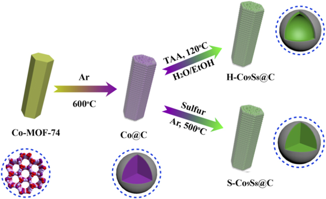
In the present study, we have successfully synthesized Co9S8@C using Co-MOF-74 as the precursor and determined their electrochemical performances for use as electrode materials for LIBs. The composite of porous carbon inlaid metal Co nanoparticles (Co@C) was first prepared by calcining Co-MOF-74 in inert atmosphere, where Co nanoparticles were approximately 5–10 nm in size and evenly dispersed in porous carbon. Subsequently, the porous carbon-coating Co9S8 hollow nanoparticles (H-Co9S8@C) and Co9S8 solid nanoparticles (S-Co9S8@C) were separately synthesized by solvothermal method with thioacetamide and sulfur vapor sulphurisation. As the anode materials for LIBs, compared with S-Co9S8@C, H-Co9S8@C showed excellent rate and charge/discharge cycle performance.
II. EXPERIMENTAL
A. Synthesis of Co@C
The synthesis of MOF-74 was based on a previously reported method.Reference Li, Yue, Yang, Qiu, Xue, Xu and Wang35,Reference Li, Chi, Yang, Zhang, Yue and Wang36 2,5-Dihydroxyterephthalic acid (DHTP, 3 mmol) was dissolved in 40 mL tetrahydrofuran. Meanwhile, cobalt acetate (3 mmol) and hexadecyl trimethyl ammonium bromide (CTAB, 1.0 g) were dissolved in 40 mL DI water. The two solutions were mixed under stirring for 10 min, and then the solution was transferred into a bottle with plug, which was heated and stirred magnetically to 110 °C for 3 h in an oil bath. After the mixture was cooled naturally to room temperature, the precipitate was collected with centrifugation, washed with DI water and ethanol for three times and dried in a vacuum at 60 °C for 12 h. The as-prepared Co-MOF-74 was calcined in the tube furnace in Ar atmosphere, heated up to 600 °C at 2 °C/min and then maintained for 3 h. The obtained product was marked as Co@C.
B. Synthesis of H-Co9S8@C and S-Co9S8@C
A total of 0.2 g of the above as-prepared Co@C was dispersed into 60 mL of ethanol. After ultrasonication for 2 min, 10 mL of solution containing 0.4 g of thioacetamide was poured into the above suspension under magnetic stirring for 10 min. Subsequently, the obtained mixture was transferred into a 100 mL Teflon-lined stainless-steel autoclave and kept at 120 °C for 12 h. The final product was collected by centrifugation, washed with DI water and ethanol for three times and dried in a vacuum at 50 °C for 12 h. The product was designated as H-Co9S8@C. For comparison, 0.2 g of Co@C was placed at the end of a corundum crucible, and 0.1 g of S powder was placed on the start of the crucible and into a tube furnace with Ar. Also, the temperature was increased up to 500 °C and maintained for 2 h. The obtained product was marked as S-Co9S8@C.
III. INSTRUMENTS AND CHARACTERIZATION
Powder X-ray diffraction (PXRD) was performed on a Bruker D8 Advance powder X-ray diffractometer using Cu Kα radiation (Bruker Corporation, Karlsruhe, Germany). Scanning electron microscopy (SEM) was conducted using a Hitachi SU8010 (Hitachi, Tokyo, Japan). Meanwhile, high-resolution transmission electron microscopy (HR-TEM) investigations were performed using a JEOL 1200 (JEOL, Tokyo, Japan). X-ray photoelectron spectroscopy (XPS) was performed using an ESCA-3400 spectrometer (Shimadzu, Tokyo, Japan). Nitrogen sorption isothermals were tested using an automatic volumetric adsorption equipment to calculate the specific surface area and pore size distribution of the sample (Quantum Design, Inc., San Diego, CA). Thermogravimetric analysis (TGA) data were collected by using a Shimadzu DTG-50 thermal analyser from room temperature to 800 °C at a rate of 10 °C/min (Shimadzu, Tokyo, Japan). Raman spectra were obtained using a micron-focused Raman spectrometer (DXR, Thermo Electric Company, Saddle Brook, NJ).
The electrochemical performances of the as-prepared materials were measured by using two-electrode standard CR2032-type coin cells. The work electrodes were prepared by mixing the as-products, acetylene black, and polyvinylidene difluoride with N-methyl pyrrolidone as the solvent in the weight ratio of 7:2:1 and casting the slurry on the Cu foil. Subsequently, the electrodes were dried under vacuum at 80 °C for 12 h. The mass coating active materials in each cell was about 1.2 mg/cm. A Li foil was used as the counter electrode and 1 M LiPF6 in a mixture of ethylene carbonate/diethyl carbonate (1:1 in volume) was used as the electrolyte. Cyclic voltammetry (CV) and electrochemical impedance spectra were performed using a Zennium Zahner electrochemical workstation (ZAHNER-Elektrik GmbH & Co.KG, Kronach, Germany). The charge/discharge cycling capacity was performed using a CT2001A cell test instrument (LAND Electronic Co., Wuhan, China).
IV. RESULTS AND DISCUSSION
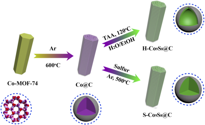
Scheme 1 illustrates the reason why we chose Co-MOF-74 as an ideal precursor and the detailed formation process of the anode materials. Co-MOF-74 is formed by interconnection of 2,5-dihydroxyl terephthalic acid as the ligand and Co2+ as the metal ion, which is a 3D frame structure. Co-MOF-74 not only has abundant carbon source, metal source, large rate surface area, and pore structure but also has three Co2+ clusters that are separated by organic ligands. After pyrolysis, Co-MOF-74 can provide uniformly dispersed Co nanoparticles, which were embedded on porous carbon. The formation mechanism of hollow Co9S8 suggested that because of the Kirkendall effect and anion exchange, the nanosized cobalt initially reacted with S2− from thioacetamide to form the surface layer of Co9S8 on the external surfaces. In the reaction process, due to larger size, S2− ions diffuse more slowly than Co2+ ions and the newly formed Co9S8 nuclei will grow on the performed Co9S8 skeleton, while the central region of the nanoparticles would be completely etched away and then gradually transformed into the hollow Co9S8.Reference Li, Yue, Xie, Yang, Zhang, Zhang and Wang37–Reference Yu, Xia, Wang and Lou40 While using the reaction of S steam with Co@C in high temperature, due to the absence of the process of dissolution and recrystallization with S2−, Co nanoparticles cannot form the hollow Co9S8, resulting in solid Co9S8.
Schematic illustration of the synthesis procedure of H-Co9S8@C and S-Co9S8@C.
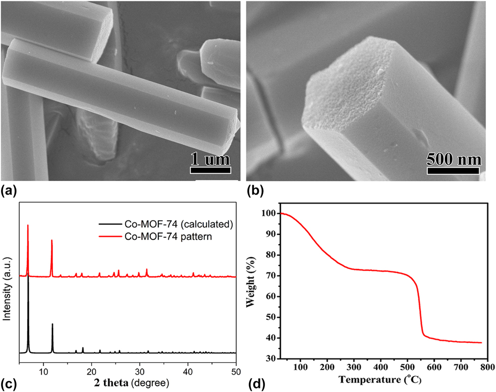
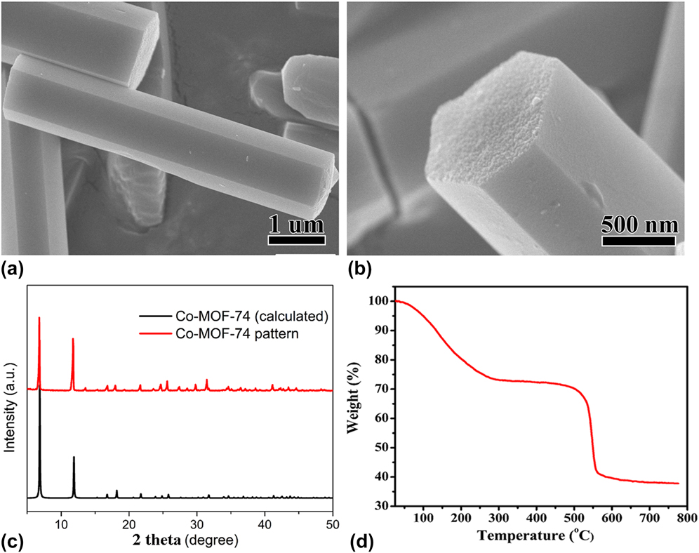
The morphology of the sample was determined by SEM. As shown in Figs. 1(a) and 1(b), the hexagonal prisms with smooth surfaces were synthesized. The PXRD pattern was measured to indicate the phase of the precursor [Fig. 1(c)]. All diffraction peaks were well matched with the simulated pattern. We studied the thermal decomposition process of Co-MOF-74 in inert atmosphere from room temperature to 800 °C at a rate of 10 °C/min. The TG curve showed two decomposition processes. From room temperature to about 300 °C, Co-MOF-74 gradually lost weight, and the weightlessness rate was about 27%, which was attributed to the gradual loss of the crystal water molecules and the coordination water molecules in the Co-MOF-74 channel with the gradual increase of temperature. In the range of about 500–560 °C, the mass rapidly decreased, and the weight loss rate was about 32%, due to the loss of carbon and oxygen atoms in the carboxyl and hydroxyl atoms in DHTP. After the temperature increased up to 600 °C, the mass of the precursor started to stay constant [Fig. 1(d)]. Based on the result of TG, the decomposition temperature was chose at 600 °C.
SEM images (a and b), XRD pattern (c), and TG curve (d) of Co-MOF-74.
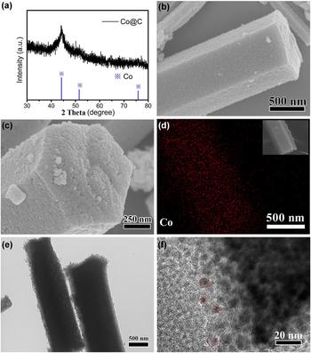
After decomposition of the precursor, the results of XRD characterization proved that the product was metal Co (JCPDS no. 15-0806) [Fig. 2(a)]. Similar phenomena where the diffraction peaks are weak because of the small metal nanoparticles have been reported.Reference Lü, Wang, Li, Lin, Jiang, Xie, Kuang and Zheng41,Reference Torad, Hu, Ishihara, Sukegawa, Belik, Imura, Ariga, Sakka and Yamauchi42 Compared with Co-MOF-74, Co@C maintained the shape of the precursor, but the surface became rough [Figs. 2(b) and 2(c)]. From the figure, the surface of Co@C was composed of homogeneous nanoparticles. As shown in Fig. 2(d), Co element is evenly distributed in the hexagonal prisms. By using TEM characterization to reveal the structural characteristics of Co@C, the light- and dark-determined Co@C showed porosity, and Co metal nanoparticles were dispersed in porous carbon [Figs. 2(e) and 2(f)], in which the size is about 5–10 nm.
XRD pattern (a), SEM images (b and c), elemental mapping for Co (d), and TEM images (e and f) of Co@C.

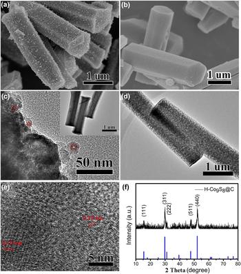
After porous Co@C was reacted with thioacetamide by the solvothermal method, the morphology was maintained [Fig. 3(a)], and TEM characterization explained the porosity of the product. However, unlike Co nanoparticles in Co@C, which were solid structures, the nanoparticles of the product had obvious hollow structures, and the hollow particles were embedded in the graphite carbon layer [Fig. 3(c)]. Sulfide was characterized by XRD [Fig. 3(f)], showing obvious diffraction patterns of Co9S8. Among them, the diffraction spectra located at 15.4°, 29.8°, 31.2°, 47.5°, and 52.1° corresponded to the Co9S8 crystal planes of (111), (311), (222), (511), and (440), respectively. The HR-TEM image reveals the distinct lattice fringes with the d spacing of 0.29 and 0.19 nm, which are matched with the (311) and (511) lattice planes of Co9S8. The formation of hollow structures was considered to be the consequence of the recrystallization of the sulfur ions in the solution after the dissolution of Co nanoparticles.
SEM images of H-Co9S8@C (a) and S-Co9S8@C (b); TEM (c) and HR-TEM (e) images of H-Co9S8@C and S-Co9S8@C (d); XRD pattern of H-Co9S8@C (f).

To study the difference of electrochemistry between hollow and solid structures, the carbon-coated solid Co9S8 (S-Co9S8@C) was synthesized by using the reaction of S steam and Co@C in high temperature. S-Co9S8@C also kept the original shape of Co@C, and S-Co9S8 was evenly dispersed in the porous carbon with very small nanoparticles [Figs. 3(b) and 3(d)].
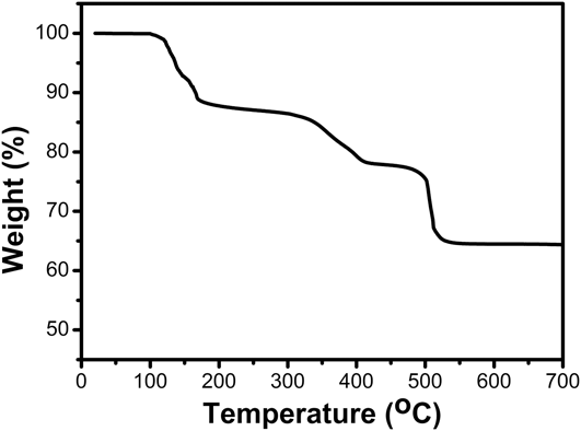
TGA was used from room temperature to 700 °C in air to investigate the Co9S8’s content and decomposition details of the composite. As shown in Fig. 4, from 20 to 150 °C, about 8% weight loss of the composite was observed, which is attributed to the evaporation of water. From the temperature range of 150–700 °C, a continuous weight loss was observed. At 516 °C, there was an actual weight loss, which can attribute to the oxidation and conversion of Co9S8 to Co3O4.Reference Huang, Chen, Wang, Chang and Chen43,Reference Ramachandran, Saranya, Santhosh, Velmurugan, Raghupathy, Jeong and Grace44
TGA of H-Co9S8.

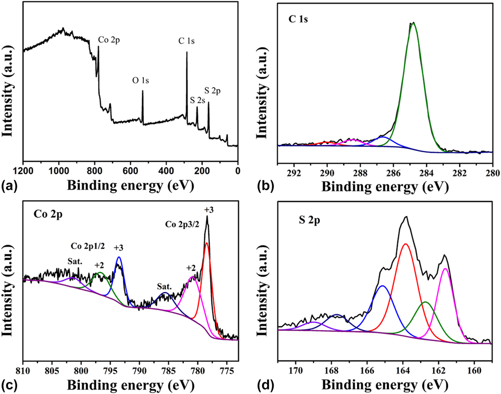
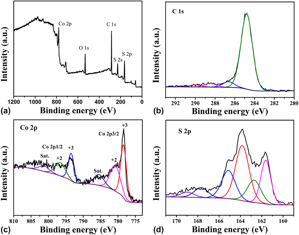
XPS was pwerformed to research the element valences of H-Co9S8@C. As shown from the general spectrum, C, Co, S, and O elements were found in the complex, and the O elements were considered to be absorbed O2Reference Kong, Lu, Zhang, Pu and Wang45,Reference Wang, Xia, Wang, Shi and Fang46 [Fig. 5(a)]. The high-resolution spectrum of C 1s was divided into three peaks, and the binding energies located at 284.8, 286.6, 288.4, and 289.1 eV belonged to C–C/C=C, C–O, and C=OReference Fan, Yu, Ling, Yang and Qiu39,Reference Fang, Jia, Chang, Ruan, Wang, Chen and Wang47,Reference Kong, Mao, Lin, Wei, Bu and Feng48 [Fig. 5(b)]. Figures 5(c) and 5(d) show the high-resolution spectra of Co 2p and S 2p, respectively, proving that Co2+ and Co3+ valence states were found in the spectrum. The peak located at 778.4 eV was considered as Co 2p 3/2, and that at 161.5 eV as S 2p 3/2, which were consistent with Co9S8 reported in the literature.Reference Mujtaba, Sun, Huang, Zhao, Arandiyan, Sun, Xu and Zhu34,Reference Wang, Pan, Hu and Zhao49 XPS analysis further proved that Co9S8@C was synthesized successfully.
(a) XPS survey spectra of H-Co9S8@C. High resolution XPS measurements for the C 1s (b), Co 2p (c), and S 2p (d) spectra of the H-Co9S8@C.
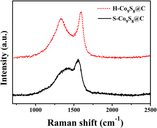
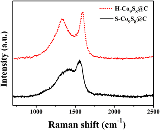
Raman spectra are shown in Fig. 6. The two main peaks corresponded to the D peak (1338 cm−1) and G peak (1587 cm−1) of carbon in H-Co9S8@C and S-Co9S8@C.Reference Kim, Mhamane, Kim, Roh, Aravindan, Madhavi, Roh and Kim50,Reference Kokai, Sorin, Chigusa, Hanai, Koshio, Ishihara, Koga, Hasegawa, Imanishi and Takeda51 The D peak matched the defects and disorder of carbon, and the G (graphite) peak belonged to the sp 2 hybridization of carbon atom, corresponding to the graphitization of carbon. The degree of defect or disorder is considered greater with the increase of the ratio of D peak to G peak (I D/I G). By calculation, the I D/I G value of H-Co9S8@C and S-Co9S8@C was 0.91 and 0.75, respectively. This result indicated that the carbon in S-Co9S8@C had higher graphitization than that in H-Co9S8@C.
Raman spectra of H-Co9S8@C and S-Co9S8@C.
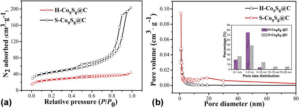
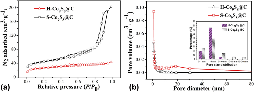
To measure the specific surface and distribution of pore diameter of H-Co9S8@C and S-Co9S8@C, N2 adsorption–desorption tests were conducted at 77 K [Fig. 7(a)]. The results indicated that both materials showed a type IV adsorption H-3 hysteresis curve. The specific surface of H-Co9S8@C was 127.1 m2/g, which was less than that of S-Co9S8@C (198.2 m2/g). The pore diameter distribution revealed that both were mesoporous materials [Fig. 7(b)].
(a) N2 adsorption–desorption isotherm and (b) the corresponding pore-size distribution of H-Co9S8@C and S-Co9S8@C.
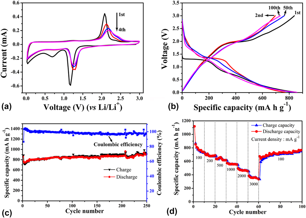
The performance of H-Co9S8@C as the anode material for LIBs was explored. Figure 8(a) shows the cyclic voltammograms for the 1st, 2nd, 3rd, and 4th cycles at a current density of 0.1 A/g. During the first anodic scan, an obvious peak was noticed at 1.77 V, which suggests that Co9S8 was reduced to Co0, at the same time Li2S was formed. The peak at approximately 0.7 V was attributed to the formation of the solid electrolyte interface (SEI) film. On the first cathodic sweep, the oxidation peak appeared at approximately 2.08 V, which is ascribed to the reversible oxidation from Co0 to Co9S8. Meanwhile, at around 2.38 V, the peak indicated that partial Co0 was oxidized to CoSx.Reference Mujtaba, Sun, Huang, Zhao, Arandiyan, Sun, Xu and Zhu34 During the second reduction process, the reduction peak at 0.70 V disappeared, which proved that the formation of the SEI film was not reversible.Reference Meng and Deng52 From the second cycle, the reduction peak of Co9S8 and the oxidation peak of Co0 shifted to 1.27 and 2.18 V, respectively, due to the rearrangement of the structure or reduction of electrode polarisation.Reference Zhou, Yan, Xu, Liu, Yang and Qian53 Obviously, the CV curve was constant approximately from the 2nd cycle, and the 3rd and 4th cycles basically coincided, proving that H-Co9S8@C has highly reversible electrochemical property.
(a) Cyclic voltammograms for the 1st, 2nd, 3rd, and 4th cycles at 0.1 A/g; (b) 1st, 2nd, 50th, and 100th charge–discharge voltage profiles; (c) cyclic stability of H-Co9S8@C at 0.1 A/g in the potential range of 0.01–3.00 V; (d) rate capacities of H-Co9S8@C at different rates.
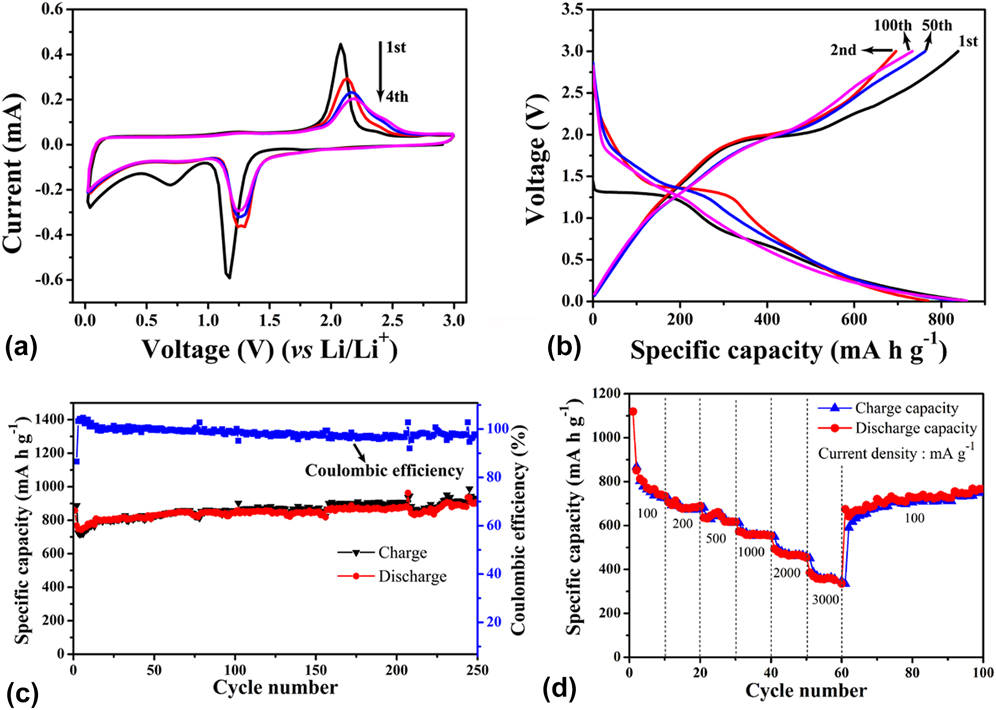
The 1st, 2nd, 50th, and 100th charge/discharge curves of the H-Co9S8@C electrode are shown in Fig. 8(b) at a current density of 0.1 A/g. In the initial discharge, the typical voltage plateau was observed at around 1.3 V, which was believed to form LixCo9S8 and SEI films, and the corresponding first charge plateau was about 2.0 V. The initial discharge/charge capacitances were 867.3 and 1119.5 mA h/g, respectively, showing that the first Coulomb efficiency was 77.4%. The capacity loss resulted from the formation of the SEI layer, which can be proved by the CV curves. The cyclic stability of H-Co9S8@C was tested at 0.1 A/g in the potential range of 0.01–3.00 V [Fig. 8(c)]. The discharge capacitance remained at 900.5 mA h/g after 250 cycles, and the Coulomb efficiency was about 98%.
The rate capacity is another important parameter of the electrode material. In Fig. 8(d), H-Co9S8@C showed high rate capacities of 850, 670, 613, 552, 457, and 347 mA h/g at 0.1, 0.2, 0.5, 1, 2, and 3 A/g, respectively. After lowering the rate to 0.1 A/g, the capacity of 674.3 mA h/g was restored. Meanwhile, the capacity gradually increased to 770 mA h/g at the 100th cycle. The result revealed that H-Co9S8@C showed a good rate performance as the anode material of LIBs.
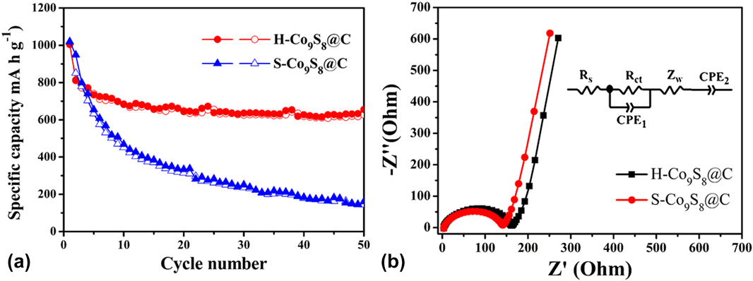
To indicate the importance of the hollow structure for the electrochemical stability, the charge/discharge cycle test was carried out on H-Co9S8@C and S-Co9S8@C at a current density of 0.5 A/g [Fig. 9(a)]. At the current density, the initial charge/discharge capacities of H-Co9S8@C were 811 and 1003.6 mA h/g, whereas those of S-Co9S8@C were 849.9 and 1018.9 mA h/g, respectively. Over 50 cycles, the discharge specific capacity of H-Co9S8@C was still maintained at 655 mA h/g. However, the capacity of S-Co9S8@C declined rapidly to 160.4 mA h/g, which suggested that the solid Co9S8 nanoparticles were crushed. The ultra-small size and hollow structure of Co9S8 as the anode material for LIBs improved the cyclic stability.
(a) Cycling performance of H-Co9S8@C and S-Co9S8@C electrodes at a current density of 0.5 A/g; (b) electrochemical impedance spectra of H-Co9S8@C and S-Co9S8@C.
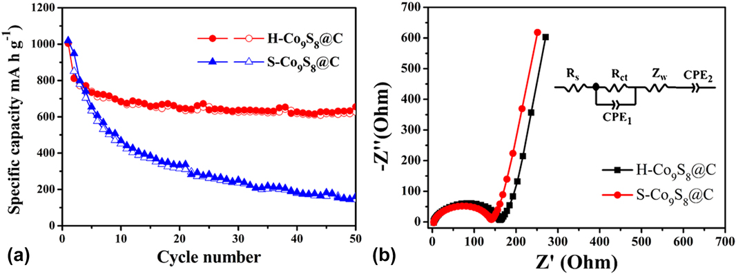
The electrochemical impedance spectra of H-Co9S8@C and S-Co9S8@C are shown in Fig. 9(b). The X-intercept is considered as the equivalent series resistance (R s). The semicircle diameter in the high frequency is the charge transfer resistance (R ct), which corresponded to the diffusion and transfer impedance of Li+ through the SEI layer. S-Co9S8@C revealed smaller R s (3.34 Ω) and R ct (135.1 Ω) than the H-Co9S8@C (R s = 3.06 Ω, R ct = 160.3 Ω), which proved that S-Co9S8@C had smaller charge transfer impedance than H-Co9S8@C. However, the charge/discharge cycle performance of S-Co9S8@C was poorer than that of H-Co9S8@C. The result further proved that the hollow structure of ultra-small Co9S8 could significantly improve the stability of the electrode. The excellent stability and discharge/charge capacitances of H-Co9S8@C can probably be credited to its special microstructure. On the one hand, the hollow Co9S8 can provide maximum buffer space to alleviate stress change of the insertion–extraction of Li+.Reference Sun, Xin, Hu, Yu, Shao, Sun and Lian18,Reference Zhou, Liu, Cai, Zhu, Liang, Zhang, Lan, Jiang, Wang and Qian19 On the other hand, uniformly dispersed and isolated ultra-small hollow Co9S8 nanoparticles can effectively prevent the aggregation of active nanoparticles in the charge/discharge process.Reference Liu, Wu, Xiao, Kopold, Gu, van Aken, Maier and Yu17,Reference Li, Gu, Guo, Samuelis, Tang and Maier54
V. CONCLUSION
H-Co9S8@C had been successfully synthesized by Co-MOF-74 as the precursor and was studied as the electrode material for LIBs. At a current density of 0.1 A/g, compared with the initial capacity, at over 250 cycles, the capacity still showed an upward trend, which was maintained at 900.5 mA h/g. To determine the effect of the hollow structure on electrochemical properties, the charge/discharge cycles of H-Co9S8@C and S-Co9S8@C were carried out at a current density of 0.5 A/g. Compared with S-Co9S8@C, H-Co9S8@C showed excellent rate and charge/discharge cycle performance. The results also showed that, compared with the large surface area and high conductivity, the hollow structure played a more important role in improving cyclic stability.
ACKNOWLEDGMENTS
We gratefully acknowledge the financial support from the National Natural Science Foundation of China (No. 21261022) and the Regional Collaborative Innovation Project of Xinjiang Uyghur Autonomous Region (No. 2017E01005) and the University Scientific Research Project of Xinjiang Uyghur Autonomous Region (No. XJEDU2017I001).