1. INTRODUCTION
Strapdown Inertial Navigation Systems (SINS) are widely used for position, location and navigation of land, sea and air vehicles (Marantos et al., Reference Marantos, Koveos and Kyriakopoulos2015; Gao et al., Reference Gao, Xue, Zhong and Gu2015). However, initial alignment must be carried out prior to the navigation operation, and the performance of initial alignment directly affects the subsequent navigation accuracy (Xiong et al., Reference Xiong, Guo and Yang2014). For SINS, since initial velocity and position can be easily obtained by external reference navigation systems such as the Global Positioning System (GPS), the purpose of initial alignment is to determine the Direction Cosine Matrix (DCM) rotating from body frame to navigation frame (Wu and Pan, Reference Wu and Pan2013). Typically, this process can be divided into two phases: coarse alignment and fine alignment (Chang et al., Reference Chang, Li and Chen2015b; Li et al., Reference Li, Wu, Wang and Lu2013b; Hu and Cheng, Reference Hu and Cheng2014). The objective of coarse alignment is to prepare for fine alignment, and misalignment angles are estimated to a few degrees. Fine alignment will be executed after coarse alignment.
Recently, in-motion alignment has also drawn increasing attention, due to special requirements, for example, natural disaster rescue and some military applications (Kang et al., Reference Kang, Fang and Wang2012; Hong et al., Reference Hong, Lee and Park2004). In contrast to static alignment, the implementation of in-motion alignment needs external reference information. When a vehicle is in motion, velocity information projected in the body frame (b-frame) is usually selected as the external reference (Li et al., Reference Li, Wu, Wang and Lu2013b; Hu and Cheng, Reference Hu and Cheng2014; Alahyari et al., Reference Alahyari, Rozbahani and Habibzadeh2011), and it is also easily obtained from external navigation devices such as Odometers (OD), Doppler Velocity Logs (DVL) and so on.
For in-motion alignment, a closed-loop Kalman Filter (KF) is one of the most widely used methods. Because the heading misalignment angle is not completely observable and a coupling between linear movement errors and heading error exists, however, heading error is very sensitive to system errors, which may lead to filter divergence, especially in high latitude regions (Sun et al., Reference Sun, Wang, Zhao and Wang2013; Zhao et al., Reference Zhao, Qin and Yan2008; Gao et al., Reference Gao, Wei, Zhong and Feng2014a). In traditional north-oriented mechanisation, the propagation of heading error is proportional to both linear movement errors and the tangent function of latitude (Li et al., Reference Li, Ben, Yu and Tan2015; Salychev, Reference Salychev2004). Therefore, even if a small east velocity error exists in high latitude regions, it would also cause a very large estimation oscillation. This is one of the major problems for high latitude alignment and the navigation errors are enlarged sharply in high latitude regions (due to SINS modelling problems).
On the other hand, in order to maintain the stability of the alignment system, an accurate coarse alignment is required (Silson, Reference Silson2011; Schimelevich and Naor, Reference Schimelevich and Naor1996; Lu et al., Reference Lu, Xie and Li2016). This gives small initial system errors and thus decreases the risk of a divergent alignment. However, to guarantee the accuracy of coarse alignment, significant time may be required. Setting larger initial values of the noise matrix can reduce filter gain, thereby decreasing the influence of system errors. This method can guarantee the stability and robustness of the alignment system at the expense of alignment performance (Pei et al., Reference Pei, Zhu and Zhao2015; Li et al., Reference Li, Wang, Lu and Wu2013a). Furthermore, Adaptive Kalman Filtering (AKF) is also proposed to improve the stability and robustness of the alignment system (Ali and Ushaq, Reference Ali and Ushaq2009; Gao et al., Reference Gao, Li and Zhou2014b; Weng, Reference Weng2008). AKF always uses the innovation sequence to estimate the statistical characteristics of the process and measurement noises. As a result, AKF is robust and can improve stability. However, the adaptive gain is also difficult to predict and control. In addition, according to the above description, we can find that all these methods only consider the solution from the external factors, such as coarse accuracy, process noise, and measurement noise and so on. Few methods approach the internal factors to solve the problem of the closed-loop KF, such as the inherent state model of the KF. Furthermore, since the north-oriented mechanisation is simpler and its physical principle is very clear, the local geographic frame (g-frame) is usually selected as the navigation frame (n-frame) (Li et al., Reference Li, Xu, Chang and L. Zhan2014). As a result, initial alignment can be regarded as a process of calculating a rotation matrix from the b-frame to the g-frame
 $(C_{b}^{g})$
. Consequently, Liu et al. (Reference Liu, Gao, Li, Guang and Li2016) develops an improved mechanisation based on a pseudo-Earth frame to implement static alignment for SINS. Then, the matrix
 $C_{b}^{g} $
is obtained by the pseudo-DCM and their relationship. The improved mechanisation exhibits superior performance. Therefore, the pseudo-Earth frame is also expected to apply to in-motion alignment. However, Liu et al. (Reference Liu, Gao, Li, Guang and Li2016) only investigates the static alignment with the pseudo-Earth frame.
The main contributions of the work presented here are twofold. Firstly, the alignment accuracy of velocity-aided in-motion alignment based on the pseudo-SINS modelling is analysed. Then the backward process of SINS is proposed to guarantee the alignment accuracy. The second contribution is that the dynamic SINS error model in the pseudo-Earth frame is derived. The advantages of the improved SINS modelling in dynamic alignment are also discussed. The rest of this paper is organised as follows: Section 2 presents the main principle of the pseudo-north-oriented mechanisation. In Section 3, the accuracy of in-motion alignment-based improved modelling is analysed, and a solution is proposed. The derivation of dynamic error equations and the discussion of the proposed modelling for in-motion alignment are given in Section 4. Simulations and field experiments are carried out in Section 5 and Section 6 respectively, and conclusions are drawn in Section 7.
2. MATHEMATICAL MODELLING FOR PSEUDO-NORTH-ORIENTED MECHANISATION
2.1 Definition of pseudo-frames
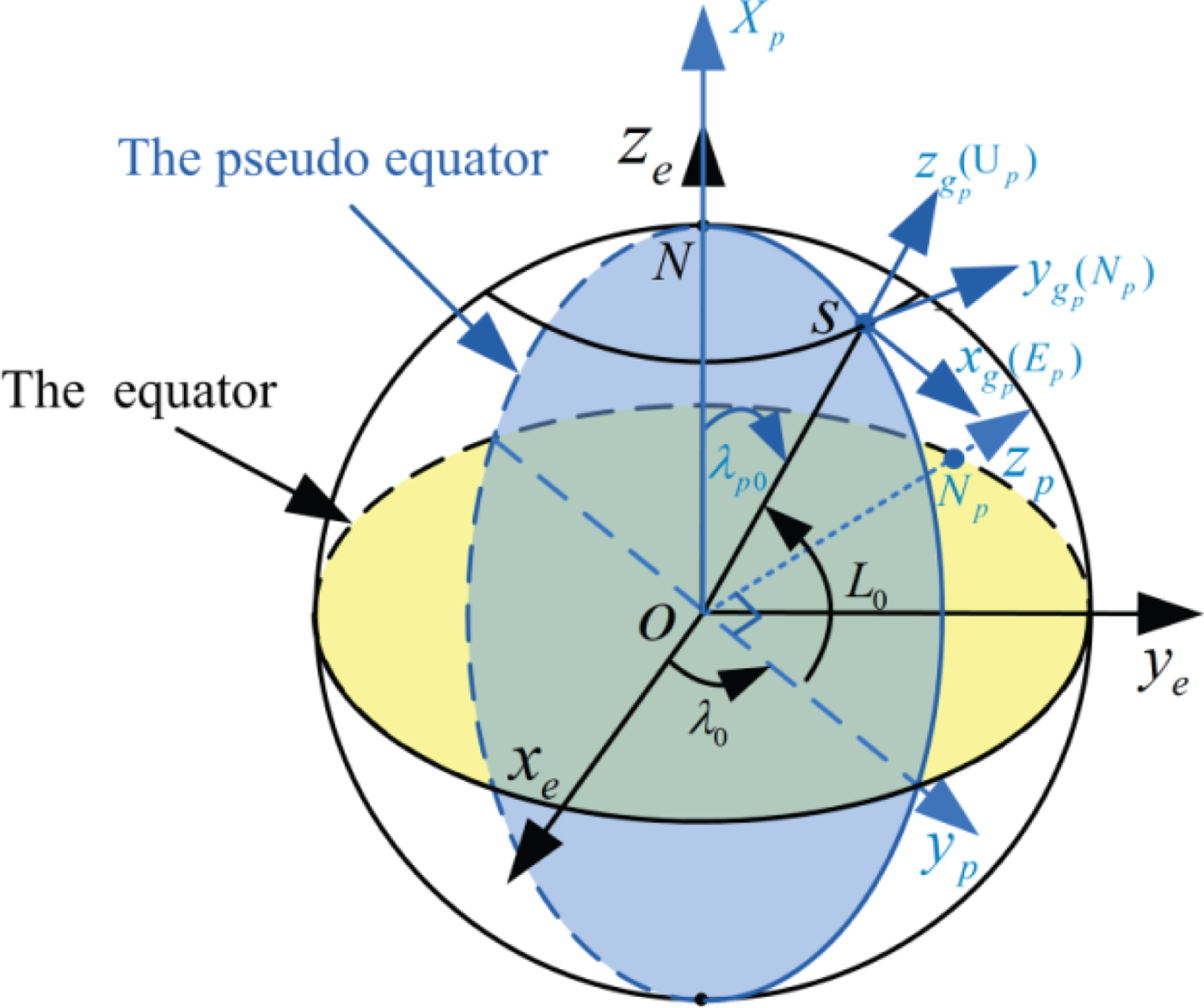
The pseudo-Earth frame (p-frame), which is re-built based on the initial position of the vehicle (latitude L
0 and longitude λ0), is obtained by two successive rotations with two Euler angles from the Earth-Centred Earth-Fixed (ECEF) frame (e-frame). As shown in Figure 1, the origin of the p-frame (
 $o_{p} x_{p} y_{p} z_{p})$
is still at the Earth's centre of mass; N
p
denotes the pseudo-North Pole; the o
p
x
p
axis overlaps with the previous o
e
z
e
axis; the o
p
y
p
axis points from the centre of Earth to the projection point of the initial position of vehicle S on the equatorial plane and the o
p
z
p
axis is perpendicular to the o
p
y
p
axis and conforms to the right hand rule, while lying in the equatorial plane. The specific rotational process can be expressed as follows:
The pseudo-coordinate system.

 $$o_ex_ey_ez_e\mathrel{\mathop{\longrightarrow}\limits_{ - {90}^ \circ }^{rotate\;around\,y_e\;axis}} o_e{x}^{\prime}_e{y}^{\prime}_e{z}^{\prime}_e\mathrel{\mathop{\kern0pt\longrightarrow}\limits_{\lambda _0 - {90}^ \circ }^{rotate\;around\;{{x}^{\prime}}_e\;axis}} o_px_py_pz_p$$
Then, the transformation matrix from the e-frame to the p-frame can be given by
 $$C_e^p (\lambda_0) = \left[ {\matrix{ 0 & 0 & 1 \cr {\cos \lambda_0} & {\sin \lambda_0} & 0 \cr { - \sin \lambda_0} & {\cos \lambda_0} & 0 \cr }} \right]$$
In the pseudo-coordinate system, pseudo-latitude and pseudo-longitude are represented by L p and λ p respectively. The pseudo-geographic frame (g p -frame) is defined as similar to the g-frame (Liu et al., Reference Liu, Gao, Li, Guang and Li2016), which is shown in Figure 1. According to the definition of the pseudo-Earth frame, the initial pseudo-position of the vehicle can be given by
 $$\lsqb {L_{p0}} \quad {\lambda_{p0}} \rsqb = \lsqb {0^{\circ}} \quad {90^{\circ} - L_0} \rsqb $$
2.2 Mathematical modelling for SINS in pseudo-Earth frame
In the pseudo-coordinate system, the g p -frame is selected as the n-frame. The SINS mechanisation in the g p -frame is similar to the one in the g-frame. Only the rotation angular rate of the pseudo-Earth frame projected in the n-frame is not identical to the traditional north-oriented mechanisation. As a result, the navigation equations in the pseudo-coordinate system can be written by (Salychev, Reference Salychev2004):
 $$\dot{C}_b^n = C_b^n (\omega_{nb}^b \times)$$
 $$\dot{V}^n = C_b^n f^b - (2\omega_{ip}^n + \omega_{pn}^n) \times V^n + g^n$$
 $$\dot{L}_p = {V_{N_p} \over {R_h}}$$
 $$\dot{\lambda}_p = {V_{E_p} \sec L_p \over {R_h}}$$
 $$\dot{h}_p = V_{U_p}$$
where
 $\omega_{ab}^{c}$
denotes the rotation angular rate of frame b relative to frame a represented in the c frame; the subscript i denotes the inertial frame;
 $\omega_{nb}^{b} = \omega_{ib}^{b} - C_{n}^{b} \omega_{in}^{n}$
,
 $C_{n}^{b} = (C_{b}^{n})^{T}$
; (*×) denotes the skew symmetric matrix of (*); f
b
denotes the specific force; g
n
denotes the gravity vector in the n-frame,
 $g^{n} = \left[0 \quad 0 \quad {-g} \right]^{T}$
; R
h
=R
e
+h
p
, R
e
denotes the Earth radius and h
p
denotes the pseudo-altitude of the vehicle. Moreover, the vectors
 $\omega_{ip}^{n}$
,
 $\omega_{pn}^{n}$
and
 $\omega_{in}^{n}$
are also given by
 $$\left\{ \displaystyle\matrix{ \omega_{ip}^n = \left[ -\Omega \sin \lambda_p \quad - \Omega \sin L_p \cos \lambda_p \quad \Omega \cos L_p \cos \lambda_p \right]^T \cr \omega_{pn}^n = \left[ -V_{N_p} / R_h \quad V_{E_p} / R_h \quad V_{E_p} \tan L_p /R_h \right]^T \hfill \cr \omega_{in}^n = \omega_{ip}^n + \omega_{pn}^n \hfill} \right.$$
where
 $\omega_{ip}^{n}$
denotes the rotation angular rate of the Earth expressed in the g
p
-frame;
 $\omega_{pn}^{n}$
denotes the rotation angular rate of the g
p
-frame with respect to the p-frame (namely, the transport rate) and Ω denotes the angular rate of Earth's rotation.
3. ANALYSIS OF PROBLEM AND SOLUTION
3.1 Analysis of in-motion alignment accuracy
When the improved SINS model is applied to in-motion alignment, the attitude matrix relative to the g-frame (namely,
 $C_{b}^{g} (\hbox{t}))$
can be obtained from the pseudo-attitude matrix (namely,
 $C_{b}^{g_{p}} (\hbox{t}))$
as follows:
 $$C_b^g (\hbox{t}) = C_{g_p}^g (\hbox{t})C_b^{g_p} (\hbox{t})$$
where
 $C_{g_{p}}^{g} (\hbox{t})$
denotes the transformation matrix from the g
p
-frame to the East-North-Up (ENU) geographic frame (namely, g-frame), and can be expressed by
 $$C_{g_p}^g (\hbox{t})=C_e^g (\hbox{t})\cdot C_p^e (\lambda_0)\cdot C_{g_p}^p (\hbox{t})$$
where
 $C_{p}^{e} =(C_{e}^{p})^{T}$
;
 $C_{g_{p}}^{p} (\hbox{t})$
is a function of pseudo-latitude and pseudo-longitude,
 $C_{e}^{g} (\hbox{t})$
is a function of latitude (L) and longitude (λ), and can be given by
 $$C_e^g (\hbox{t})=\left[ {\matrix{ {-\sin \lambda} & {\cos \lambda} & 0 \cr {-\sin L\cos \lambda} & {-\sin L\sin \lambda} & {\cos L} \cr {\cos L\cos \lambda} & {\cos L\sin \lambda} & {\sin L} \cr }} \right]$$
 $$C_{g_p}^p (\hbox{t})=\left[ {\matrix{ {-\sin \lambda_p} & {-\sin L_p \cos \lambda_p} & {\cos L_p \cos \lambda_p} \cr {\cos \lambda_p} & {-\sin L_p \sin \lambda_p} & {\cos L_p \sin \lambda_p} \cr 0 & {\cos L_p} & {\sin L_p} \cr }} \right]$$
Utilising the pseudo-longitude and pseudo-latitude from the pseudo-navigation calculation, Equation (12) is easily obtained. The local longitude and latitude in the e-frame can also be obtained from the pseudo-longitude and pseudo-latitude and their relationship. Suppose the position vector of the Earth's surface point S relative to the Earth is r. Then the mathematical expression of the vector r projected in the e-frame and the p-frame can be expressed by
 $$r^e = \left[ \matrix{ {(R_e +h)\cos L\cos \lambda} \cr {(R_e +h)\cos L\sin \lambda} \cr {(R_e +h)R_h \sin L} } \right]$$
 $$r^p=\left[ \matrix{ (R_e +h)\cos L_p \cos \lambda_p \cr (R_e +h)\cos L_p \sin \lambda_p \cr (R_e +h)\sin L_p } \right]$$
where h denotes the vehicle's altitude.
Then, the relationship between r e and r p can be written as
 $$r^p=C_e^p r^e$$
Substituting Equations (1), (13) and (14) into Equation (15), the position of the vehicle in the e-frame can be obtained by
 $$\sin L=\cos L_p \cos \lambda_p$$
 $$\sin \lambda = {\sin \lambda_0 \cos L_p \sin \lambda_p +\cos \lambda_0 \sin L_p \over \cos L}$$
 $$\cos \lambda = {\cos \lambda_0 \cos L_p \sin \lambda_p -\sin \lambda_0 \sin L_P \over \cos L}$$
According to Equations (16) and (11), the matrix
 $C_{e}^{g}$
can be obtained easily from the pseudo-longitude and pseudo-latitude. Then the transformation matrix
 $C_{g_{p}}^{g} (t)$
can also be obtained by Equation (10). As a result, the attitude matrix relative to the g-frame
 $C_{b}^{g} (t)$
is obtained from the calculated pseudo-position. Consequently, velocity-aided in-motion alignment with the pseudo-Earth frame can be implemented by Equation (9). However, drift errors in the calculated pseudo-position are unavoidable when external velocity information is selected as the observation information. Hence some additional alignment errors may be added, thereby affecting the alignment accuracy. Therefore, the influence of drift errors of pseudo-position on the alignment accuracy is analysed next.
According to Equation (16), the local position errors in the e-frame caused by pseudo-position errors can be given as follows:
 $$\cos L_0 \delta \lambda =\cos L_p \delta L_p$$
 $$\cos L\delta L=-\sin L_p \cos \lambda_p \delta L_p -\cos L_p \sin \lambda_p \delta \lambda_p$$
where δ L p and δλ p denote the pseudo-latitude error and pseudo-longitude error; δ L and δλ denote the latitude error and longitude error.
As L
p0=0 and the alignment process is usually completed within a short period of time, we have
 $L_{p} \approx L_{p0}$
and
 $\lambda_{p} \approx \lambda_{p0} = 90^{\circ} - L_{0}$
. Then, Equations (17) and (18) can be rewritten as follows:
 $$\delta \lambda =\sec L_0 \delta L_p$$
 $$\delta L=-\delta \lambda_p$$
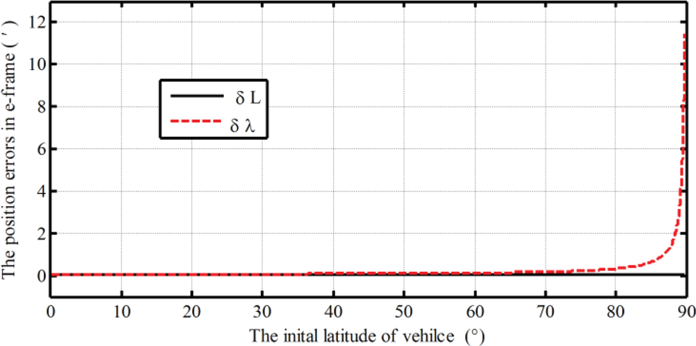
From Equations (19) and (20), the latitude error (δ L) is mainly influenced by pseudo-longitude error (δλ p ), while the longitude error (δλ p ) is proportional to both the pseudo-latitude error (δ L p ) and the secant function of initial latitude (sec L 0). Consequently, in high-latitude regions, a small pseudo-position error may cause a very large heading error. Suppose the drift errors of pseudo-longitude and latitude are all 100 m at the end of initial alignment. Then, with a different initial latitude, the influence of drift errors of pseudo-position on latitude error and longitude error is shown in Figure 2.
The influence of drift errors of pseudo-position on latitude and longitude errors at the different initial latitudes.
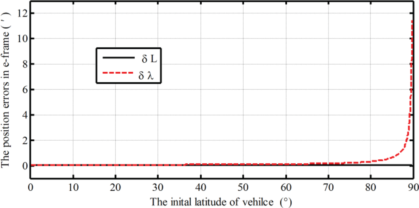
From Figure 2, the latitude error is a constant and never changes with the initial latitude of the vehicle. The influence is also very small and is only
 $0{\cdot}054^{\prime}$
when the drift errors of pseudo-longitude and latitude are 100 m. The longitude error increases with the increasing of initial latitude. Especially near the pole regions, the longitude error would become infinite. As a result, the alignment accuracy of the heading would be influenced severely by drift errors of pseudo-position in high latitude regions. Therefore, the transformational method for the attitude matrix using Equation (9) would be not an ideal solution. Thus a proper transformational method without sacrifice of alignment accuracy and influence of both position errors and initial position needs to be proposed.
3.2 Solution
By computation, nevertheless, it is easily found that the initial transformation matrix between the g
p
-frame and the g-frame at the initial position is a constant matrix and never changes with the initial position of the vehicle. Substituting Equation (2) into Equation (9), the initial transformation matrix
 $C_{g}^{g_{p}} (0)$
can be given by
 $$C_g^{g_p} (0)=\left[ {\matrix{ 0 & {-1} & 0 \cr 1 & 0 & 0 \cr 0 & 0 & 1 \cr }} \right]$$
From Equation (21), we can see that the initial transformation matrix
 $C_{g}^{g_{p}} (0)$
is a fixed known constant matrix and never influenced by the initial position of the vehicle, and the g
p
-frame (E
p
N
p
U
p
) overlaps with the traditional South-East-Up (SEU) geographic frame at the initial position. As a result, it would be very advantageous to achieve the transformation of the attitude matrix between the g-frame and the g
p
-frame. This has low transformational computational complexity, and the influence of position errors can also be removed. Therefore, if the pseudo-attitude matrix at the initial position is obtained when the initial alignment is completed, the initial attitude matrix
 $C_{b}^{g} (0)$
can be obtained directly by initial transformation matrix without the influence of both calculated position errors and initial position of the vehicle. Fortunately, the backward process for SINS can be applied to solve the problem (Chang et al., Reference Chang, Hu and Li2015a; Shin, Reference Shin2005; Gao et al., Reference Gao, Ben, Zhang, Li and Yu2011; Yan et al., Reference Yan, Yan and Xu2008).
The term “backward process” means that the operating process is opposite to the normal time direction. A traditional application of a backward algorithm is usually expected to shorten the required time for the alignment process with certain accuracy requirement or to improve the alignment performance with a certain amount of available navigation data. However, for the application of a backward algorithm to in-motion alignment based on pseudo-north-oriented mechanisation, it is expected to not only shorten alignment time, but also solve the problem of alignment accuracy influenced by initial position and position errors. As a result, there are some differences with the traditional method in implementation.
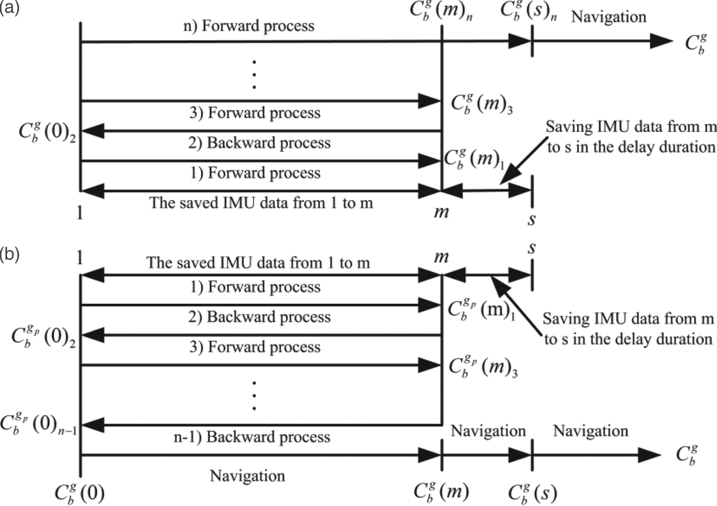
For a traditional application of a backward algorithm, the Inertial Measurement Unit (IMU) data is firstly saved during coarse alignment or during the first forward KF estimation. Suppose the IMU data is saved during the first forward fine alignment with the estimation of attitude matrix
 $C_{b}^{g} (\hbox{m})_{1}$
, and the time index of sequence is from 1 to m. Then, the backward process of the filter estimation is carried out with the estimated matrix
 $C_{b}^{g} (0)_{2}$
. Furthermore, the forward process and backward process are carried out repeatedly by the navigation computer. Since the reciprocating process will take some time, the IMU data from during the delay period also needs to be saved. The time index of the “saved” time is from m to s. Suppose the nth forward KF estimation is carried out from 1 to s, and the final estimation of alignment
 $C_{b}^{g} (s)_{n}$
is obtained. Next, the SINS starts navigation. However, the time of the KF estimation could only be n-1 in in-motion alignment with the improved model. The last attitude matrix estimation is the backward KF process with the estimated value
 $C_{b}^{g_{b}} (0)_{n-1}$
. Thus, the initial attitude matrix relative to the g-frame
 $C_{b}^{g} (0)$
can be obtained by Equation (21). Subsequently, the navigation operation is carried out from 1 to s with the initial strapdown matrix
 $C_{b}^{g} (0)$
. Then the SINS starts navigation. According to above description, for the application of the backward algorithm with a traditional model or the proposed model, the specific processes are shown in Figure 3. In addition, a more detailed derivation and implementation process for the application of the backward algorithm can be found in Gao et al., (Reference Gao, Ben, Zhang, Li and Yu2011).
Flow chart for SINS in-motion alignment based on forward and backward process. (a) Application of backward algorithm with traditional model. (b) Application of backward algorithm with proposed model.

4. DYNAMIC ERROR MODEL OF SINS WITH PSEUDO-EARTH FRAME
According to the navigation equations in Section 2.2, the pseudo-error equations with small misalignment angles can be easily derived. Since the navigation equations based on the proposed modelling are the same as the traditional ones in mathematical form, the error model of pseudo-SINS is also same as the traditional one in mathematical form. As a result, the error model in the pseudo-frame can be given by (Shin, Reference Shin2005):
 $$\dot{\phi}_p =\delta \omega_{in}^n -\omega_{in}^n \times \phi_p + \varepsilon_p^n$$
 $$\delta \dot{V}_p^n =V_p^n \times (\delta \omega_{ip}^n +\delta \omega _{in}^n)-(\omega_{ip}^n +\omega_{in}^n)\times \delta V_p^n +f^n\times \phi_p +\nabla_p^n$$
 $$\delta \dot{P}_p =\lsqb {\delta \dot{L}_p} \quad {\delta \dot{\lambda}_p} \quad {\delta \dot{h}_p} \rsqb ^T$$
where ϕ
p
,
 $\delta V_{p}^{n}$
, δP
p
,
 $\varepsilon_{p}^{n}$
,
 $\nabla_{p}^{n}$
are the pseudo-attitude error, pseudo-velocity error, pseudo-position error, constant gyroscope drift, and the constant accelerometer zero-bias vectors respectively, and
 $\phi_{p} =\left[ \phi_{x_{p}} \quad {\phi_{y_{p}}} \quad {\phi_{z_{p}}} \right]^{T}$
,
 $\delta V_{p}^{n} = \left[ {\delta V_{E_{p}}} \quad {\delta V_{N_{p}}} \quad {\delta V_{U_{p}}} \right]^{T} \delta P_{p} = \left[ {\delta L_{p}} \quad {\delta \lambda_{p}} \quad {\delta h_{p}} \right]^{T}$
,
 $\varepsilon_{p}^{n} =\left[ {\varepsilon_{E_{p}}} \quad {\varepsilon_{N_{p}}} \quad {\varepsilon_{U_{p}}} \right]^{T}$
,
 $\nabla_{p}^{n} = \left[ {\nabla_{E_{p}}} \quad {\nabla_{N_{p}}} \quad {\nabla_{U_{p}}} \right]^{T}$
,
 $f^{n}=\lsqb f_{E_{p}} \quad f_{N_{p}} \quad f_{U_{p}}\rsqb ^{T}$
. Then the rest of the vectors can also be given by
 $$\left\{ \matrix{ \delta \omega_{pn}^n =\lsqb \omega_{21} \quad \omega_{22} \quad \omega_{23} \rsqb^T \hfill \cr \omega_{21} ={V_{N_p} \over {R_h^2}}\delta h_p -{\delta V_{N_p} \over {R_h}} \hfill \cr \omega_{22} =-{V_{E_{p}} \over {R_h^2}}\delta h_p +{\delta V_{E_p} \over {R_h}} \hfill \cr \omega_{23} ={V_{E_{p}} \over {R_h}}\sec^2L_p \delta L_p -{V_{E_{p}} \tan L_p \over {R_h^2}}\delta h_p + {\delta V_{E_{p}} \over {R_h}}\tan L_p } \right.$$
 $$\left\{ \matrix{ \delta \omega_{ip}^n = \lsqb {\omega_{11}} \quad {\omega_{12}} \quad {\omega_{13}} \rsqb^T \hfill\cr \omega_{11} =-\Omega \cos \lambda_p \delta \lambda_p \hfill\cr \omega_{12} =-\Omega \cos L_p \cos \lambda_p \delta L_p +\Omega \sin L_p \sin \lambda_p \delta \lambda_p \hfill\cr \omega_{13} -\Omega \sin L_p \cos \lambda {}_p\delta L_p -\Omega \cos L_p \sin \lambda_p \delta \lambda_p \hfill} \right.$$
 $$\delta \omega_{in}^n =\delta \omega_{ip}^n +\delta \omega_{pn}^n$$
 $$\left\{ \matrix{ \delta \dot{L}_p =-{V_{N_{p}} \over {R_h}}\delta h_p +{\delta V_{N_{p}} \over {R_h}} \hfill\cr \delta \dot{\lambda}_p ={V_{E_{p}} \tan L_p \sec L_p \over {R_h}}\delta L_p - {V_{E_{p}} \sec L_p \over {R_h^2}}\delta h_p + {\delta V_{E_{p}} \over {R_h}}\sec L_p \hfill\cr \delta \dot{h}_p =\delta V_{U_p} \hfill} \right.$$
On the other hand, from Equation (2), it can be seen that the initial pseudo-latitude (L
p0) is always zero. The alignment process can usually be completed within a short period of time. As a result, in the process of initial alignment, we have
 $L_{p} \approx L_{p0} =0^{\circ}$
. Therefore, Equations (22)–(24) can be rewritten as
 $$\phi_{x_p} = -\Omega \cos \lambda_p \delta \lambda_p + {V_{N_{p}} \over {R_h^2}}\delta h_p -{\delta V_{N_p} \over {R_h}}+\phi_{y_p} \Omega \cos \lambda -\phi_{z_p} {V_{E_p} \over {R_h}} + \varepsilon_{E_p}$$
 $$\dot{\phi}_{y_p} =-\Omega \cos \lambda_p \delta \phi_p -{V_{E_{_p}} \over {R_h^2}}\delta h_p +{\delta V_{E_p} \over {R_h}}-\phi_{x_p} \Omega \cos \lambda_p -\phi_{z_p} \left(\Omega \sin \lambda_p +{V_{N_p} \over {R_h}} \right)+\varepsilon_{N_p}$$
 $$\dot{\phi}_{z_p} ={V_{E_p} \over {R_h}}\delta \phi_p -\Omega \sin \lambda_p \delta \lambda_p +\phi_{x_p} {V_{E_p} \over {R_h}}+\phi _{y_p} \left(\Omega \sin \lambda_p +{V_{N_p} \over {R_h}} \right)+\varepsilon_{U_p}$$
 $$\eqalign{ \delta \dot{V}_{E_p} =&\left({V_{E_p} V_{N_p} \over {R_h}}+2\Omega \cos \lambda_p V_{U_p} \right)\delta L_p -2\Omega \sin \lambda_p V_{N_p } \delta \lambda_p +{V_{E_p} V_{U_p} \over {R_h^2}}\delta h_p \cr &- {V_{U_p} \over {R_h}}\delta V_{E_p} +2\Omega \cos \lambda_p \delta V_{N_p} - {V_{E_p} \over {R_h}}\delta V_{U_p} -\phi_{y_p} f_{U_p} +\phi_{z_p} f_{N_p} +\nabla_{E_p}}$$
 $$\eqalign{ \delta V_{N_p} =&-{V_{E_p}^2 \over {R_h}}\delta L_p +\lpar 2\Omega \sin \lambda_p V_{E_p} -2\Omega \cos \lambda_p V_{U_p} \rpar \delta \lambda_p +{V_{N_p} V_{U_p} \over {R_h^2}}\delta h_p -2\Omega \cos \lambda_p \delta V_{E_p} \cr &-{V_{U_p} \over {R_h}}\delta V_{N_p} -\left(2\Omega \sin \lambda_p + {V_{N_p} \over {R_h}} \right)\delta V_{U_p} +\phi_{x_p} f_{U_p} -\phi_{z_p} f_{E_p} +\nabla_{N_p}}$$
 $$\eqalign{ \delta \dot{V}_{U_p} =&-2\Omega \cos \lambda_p V_{E_p} \delta L_p +2\Omega \cos \lambda_p V_{N_p} \delta \lambda_p -{V_{E_p }^2 +V_{N_p}^2 \over {R_h^2}}\delta h_p +{V_{E_p} \over {R_h}}\delta V_{E_p} \cr &+\left(2\Omega \sin \lambda_p + {V_{N_p} \over {R_h}} \right)\delta V_{N_p} -\phi_{x_p} f_{N_p} +\phi_{y_p} f_{E_p} +\nabla_{U_p}}$$
 $$\delta \dot{L}_p =-{V_{N_p} \over {R_h}}\delta h_p +{\delta V_{N_p} \over {R_h}}$$
 $$\delta \dot{\lambda}_p =-{V_{E_p} \over {R_h^2}}\delta h_p + {\delta V_{E_p} \over {R_h}}$$
 $$\delta \dot{h}_p =\delta V_{U_p}$$
From Equations (29)–(37), compared with the traditional SINS error model, it can be seen that those error items proportional to the secant or tangent function of latitude are all removed. As a result, the error propagation can never be sharply enlarged due to the initial latitude of the vehicle. Therefore, the proposed SINS modelling can decrease the degree of the enlargement of navigation errors, thereby eliminating the influence of the alignment model on the performance of the initial alignment across global regions.
On the other hand, from Equations (35)–(37), the influence of level linear movement errors
 $(\delta V_{E_{p}},\delta V_{N_{p}})$
on position errors are all only inversely proportional to R
h
. As a result, the influence of initial position (L0, δ0) on position errors is decreased, and hence the proposed algorithm can decrease the influence of level linear movement errors on position errors.
Moreover, from Equations (32)–(34), the items
 $\lpar V_{E_{p}} \tan L_{p} / R_{h} \rpar \delta V_{N_{p}}$
and
 $\lpar V_{E_{p}} \tan L_{p} / R_{h} \rpar \break \delta V_{E_{p}}$
are removed. The level linear movement errors caused by the change of latitude and longitude are eliminated. Therefore, the proposed algorithm can eliminate the influence of the transport rate on linear movement errors.
In traditional mechanisation, the heading error is proportional to both east linear movement error and the tangent function of latitude. This can be disadvantageous to in-motion alignment, especially in high latitude regions. From Equation (31), the proposed algorithm decreases the influence of velocity errors on heading error, (namely, from the influence of the transport rate errors). As a result, the proposed INS mechanisation is advantageous to in-motion alignment.
According to the above analysis, we can conclude that the proposed algorithm can decrease the influence of level linear movement and level linear movement errors on initial alignment, which is always equivalent to the traditional state model in equatorial regions. Therefore, the proposed algorithm can decrease the estimated oscillation of a closed-loop KF, thereby improving the stabilisation and anti-interference of the alignment system, and can also be applied to solve the problem of high latitude alignment caused by traditional SINS modelling.
5. SIMULATIONS
In this section, simulations are performed to show the advantage of the proposed SINS model compared with conventional north-oriented mechanisation, which is assisted by closed-loop KF. V b is selected as the external reference information. Two groups of in-motion data at different initial positions were obtained by a SINS simulator. The main parameters of the SINS simulator are as follows: the constant and random drifts of gyroscope are 0·01°/h and 0·001°/h, respectively; and the constant and random biases of the accelerometer are 100 μ g and 10 μ g, respectively. The initial longitude and latitude are (126°, 45°) and (126°, 85°) respectively; the attitudes of the SINS are all set to zero; the vehicle moves with a constant speed of 15 m/s. In all simulations, the update frequency of IMU data is 100 Hz, and the Kalman filter update time interval is set to 0·1 s.
5.1 In-motion alignment at low latitude
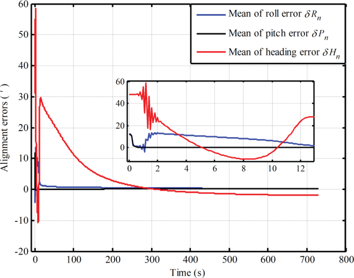
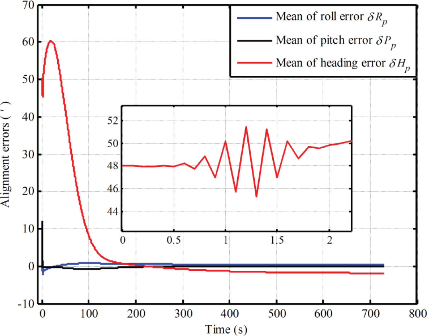
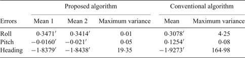
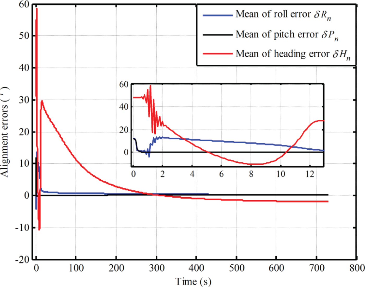
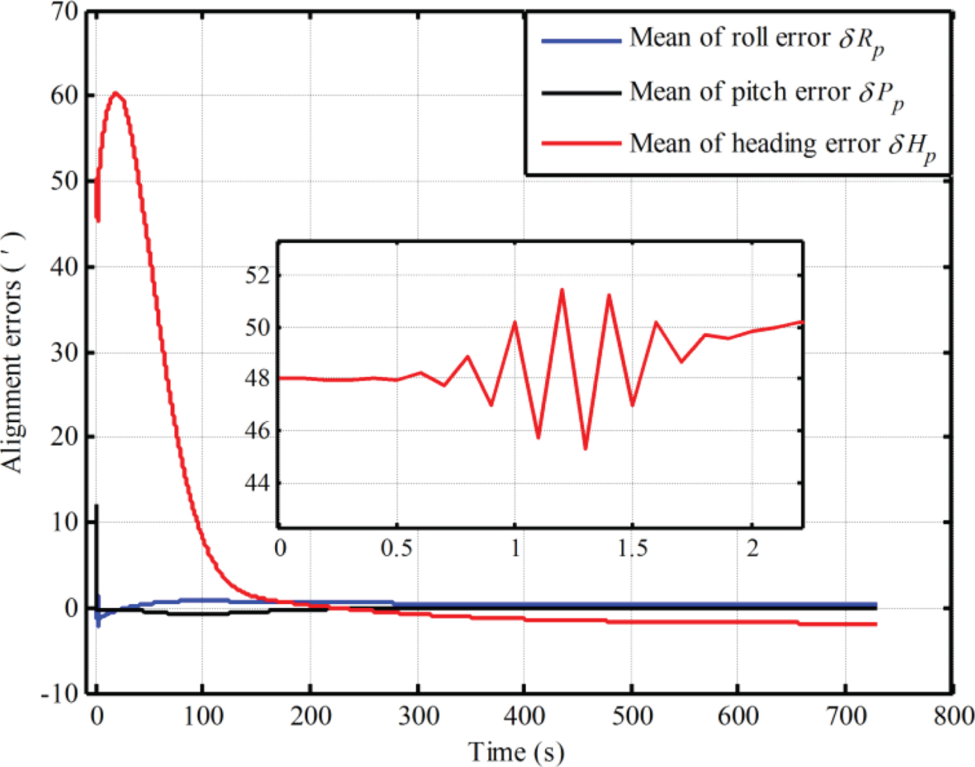
The alignment simulations at 45° latitude are conducted using Monte Carlo simulation by intentionally adding initial attitude errors (0·8° for heading, 0·2° for both pitch and roll). Table 1 shows the mean of 50 alignment errors over 700 s and the maximum value of variance curves of 50 alignment errors. In Table 1, Mean 1 denotes the mean errors of alignment results with the proposed algorithm, which is obtained by the calculated pseudo-position from pseudo-SINS calculation, while Mean 2 denotes mean errors of alignment results with the local position in the e-frame from the SINS simulator. Then, due to the limitation of the figures, only the mean error curves of alignment result are shown in Figures 4 and 5.
The simulation results of initial alignment with conventional SINS modelling.
The simulation results of initial alignment with with the proposed SINS modelling.
Mean and maximum variance of alignment errors at 45° latitude.

Comparing Figures 4 and 5, the oscillation of heading alignment error based on the traditional model is more evident at the beginning of the alignment, and the amplitudes based on the two methods are
 $42{\cdot}4^{\prime}$
and
 $6{\cdot}18^{\prime}$
, respectively. As a result, the estimated oscillation of the in-motion alignment based on the proposed algorithm is smaller, which is advantageous to the stability of the KF. The smaller oscillation can decrease the risks of filter divergence. In addition, from Table 1, the maximum variances of alignment results of three axes based on the proposed method are also smaller. As a result, the convergence of alignment results with the proposed SINS model is more stable. Furthermore, the mean errors of alignment results obtained by the two methods over 700 s have almost no difference from Table 1. Even the heading error with the pseudo-SINS modelling is smaller. This is because the proposed SINS modelling decreases the influence of transport rate errors on heading error. Therefore, the proposed SINS model has superior performance for in-motion alignment at low latitudes.
5.2 In-motion alignment at high latitude
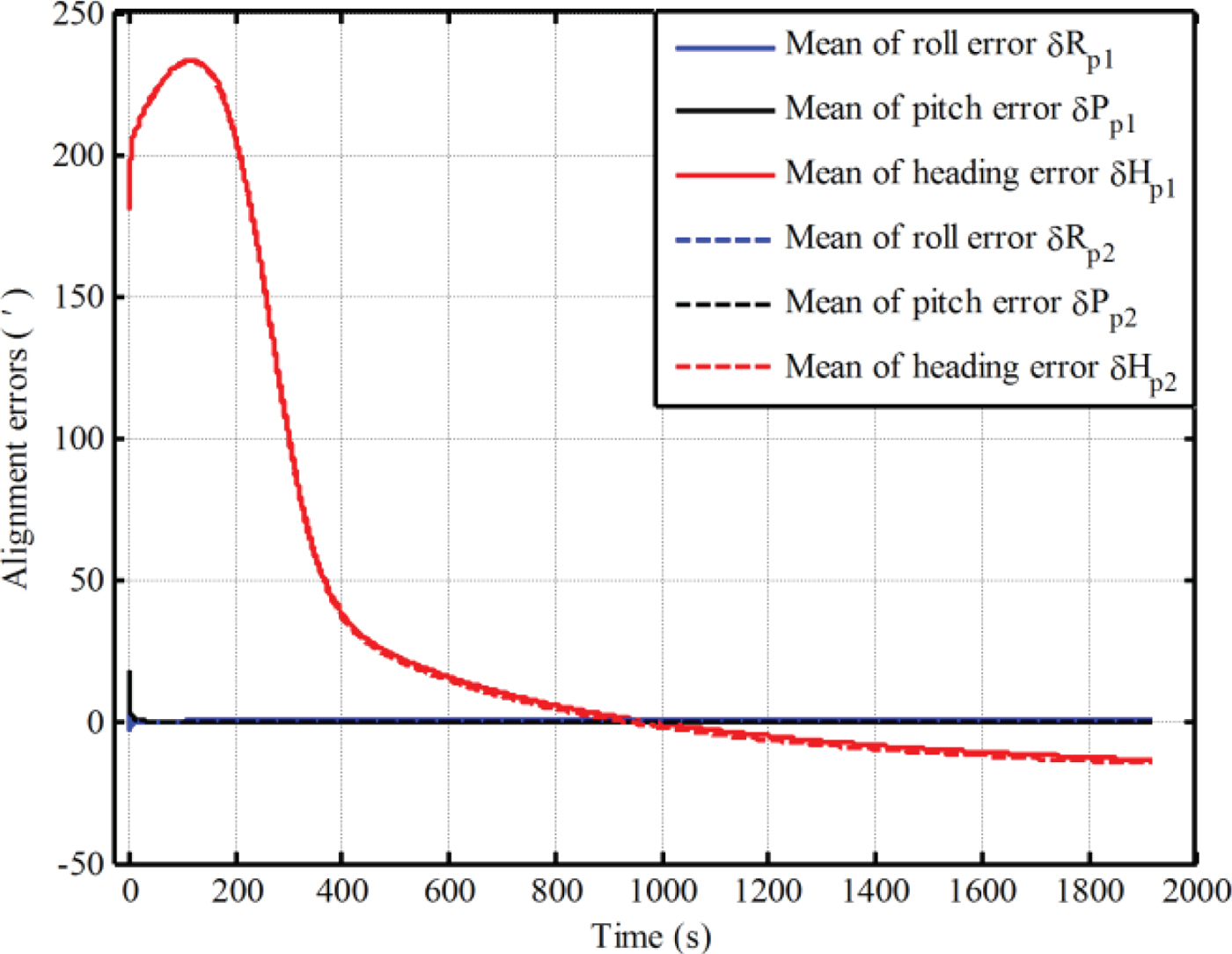
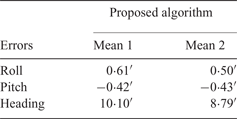
In this section, in-motion alignments at 85° latitude are performed by using the proposed SINS model. Considering that an accurate coarse heading alignment is difficult to obtain in high latitude regions, the initial attitude errors (roll, pitch and heading errors) of alignment are set to 0·3°, 0·3° and 3° respectively. The mean of 50 alignment errors over 700 s is shown in Table 2, and Mean 1 and Mean 2 denote the mean errors of alignment results obtained by the calculated pseudo-position and the local position in the e-frame from the SINS simulator, respectively. The mean error curves of alignment results based on two transformational methods are shown in Figure 6.
The alignment errors based on two methods of transformation.

Mean of alignment errors based on proposed algorithm at 85° latitude.

In Figure 6, the solid lines denote the alignment results obtained by the calculated pseudo-position and dotted lines denote the alignment results for the local position in the e-frame from the SINS simulator. Comparing the two alignment results, there is almost no difference at the beginning of alignment. However, as time passes, the differences become evident, and the alignment errors (pitch, roll and heading) based on the two methods over 1,800 s are
 $0{\cdot}35^{\prime}$
,
 $-0{\cdot}34^{\prime}$
,
 $-12{\cdot}74^{\prime}$
and
 $-0{\cdot}24^{\prime}$
,
 $-0{\cdot}30^{\prime}$
,
 $-13{\cdot}96^{\prime}$
respectively. The difference mainly comes from the drift errors of the pseudo-position. Therefore, the alignment accuracy is influenced by the drift errors of pseudo-position. Some additional alignment errors may be added, thereby decreasing the alignment accuracy.
In addition, the influence of drift errors of pseudo-position on alignment accuracy is more serious at high latitudes. From Mean 1 and Mean 2 in Tables 1 and 2, the influence of three-axis errors at 45° and 85° latitudes are
 $0{\cdot}0057^{\prime}$
,
 $0{\cdot}005^{\prime}$
,
 $0{\cdot}0059^{\prime}$
and
 $0{\cdot}11^{\prime}$
,
 $0{\cdot}01^{\prime}$
,
 $1{\cdot}31^{\prime}$
, respectively. This is consistent with the analysis results concerning alignment accuracy in Section 3.1. As a result, the transformational method based on the calculated pseudo-position is not an ideal solution for in-motion alignment, especially for high latitude alignment.
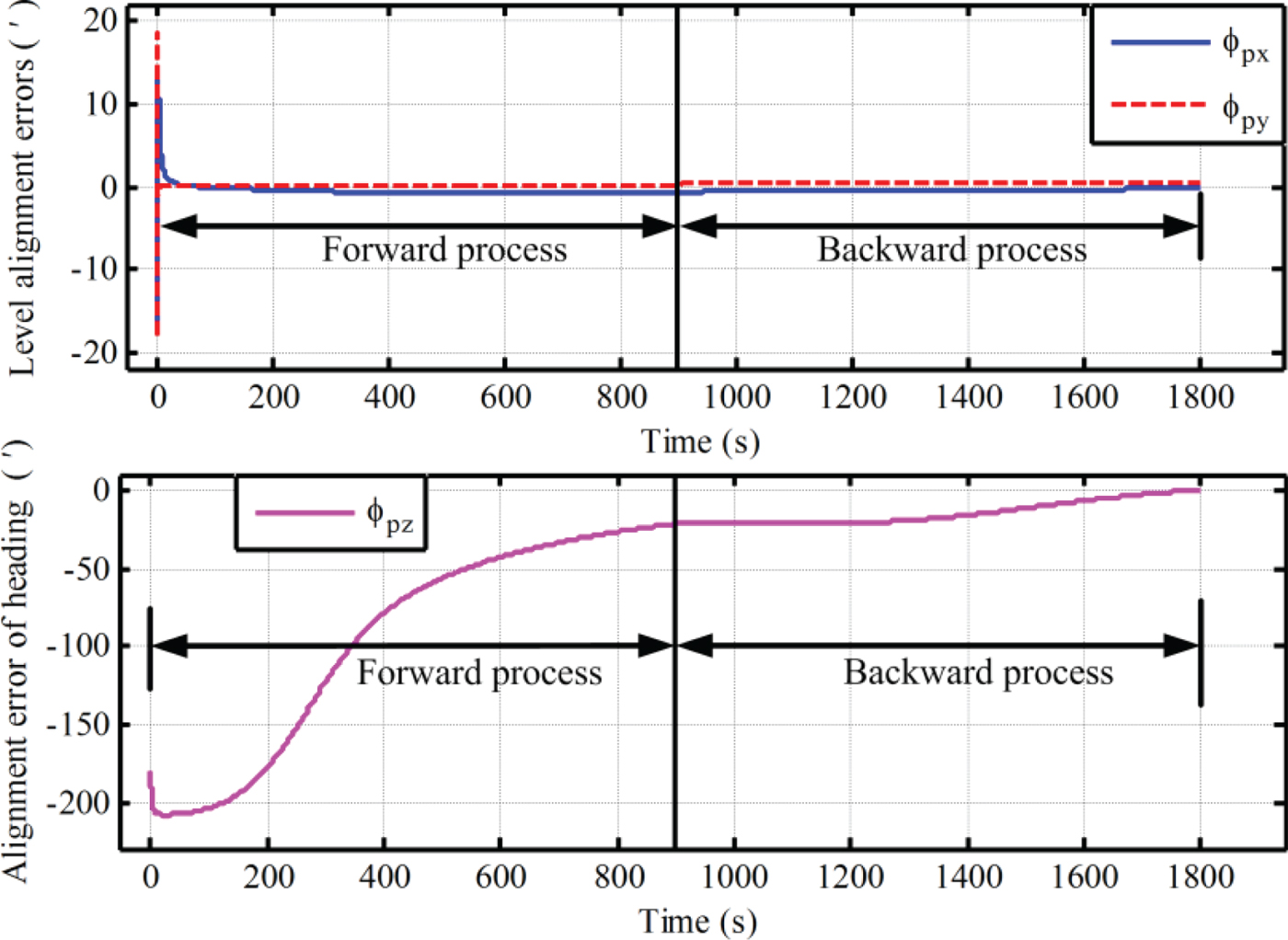
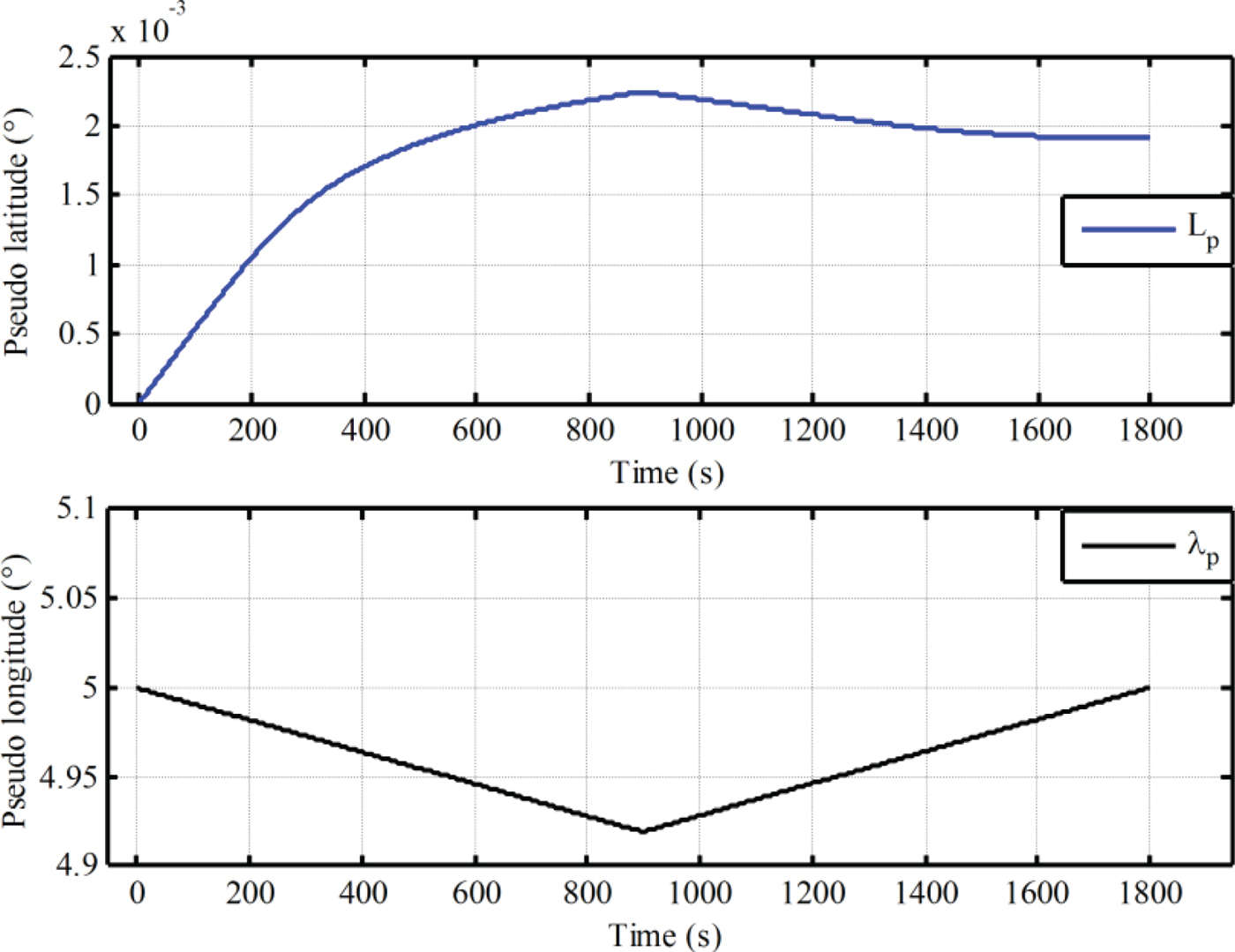
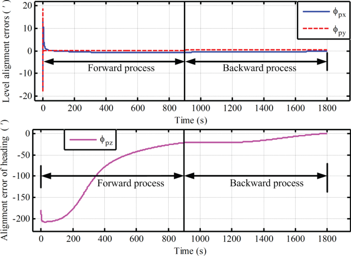
Furthermore, the proposed alignment algorithm based on the backward process at 85° is also conducted. Since this paper mainly focuses on the design of the alignment scheme with the pseudo-SINS modelling, the application of a backward process to accelerate the alignment process has not been presented. A backward process is only conducted here to implement initial alignment. For the application of a backward process to decrease the alignment time further, more details can be found in Shin (Reference Shin2005) and Gao et al. (Reference Gao, Ben, Zhang, Li and Yu2011). The in-motion data over 900 s were collected to implement the high latitude alignment, and the alignment results based on the backward process are shown in Figures 7 and 8.
The alignment errors of three axes based on the proposed SINS modelling associated with the backward process.
The calculated pseudo-latitude and pseudo-longitude in the process of initial alignment with the proposed algorithm.
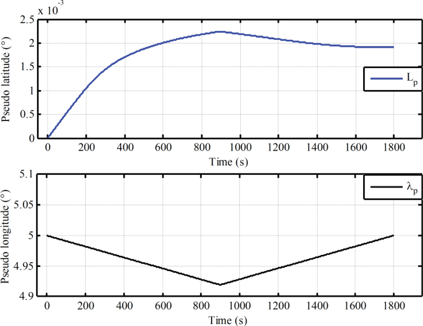
From Figure 7, the three-axis alignment errors are convergent with time and a better alignment result is obtained with the proposed alignment scheme, even in high latitude regions. This is because the proposed SINS model can eliminate the influence of alignment model on the performance of initial alignment. Therefore, the proposed alignment algorithm can be applied to solve the problem of high latitude alignment caused by SINS modelling. On the other hand, from Figure 8, we can see that the calculated pseudo-position returns to the initial position when the initial alignment is completed, although there are still some differences between the initial value and the calculated final value of pseudo-position. The drift errors in the calculated pseudo-position are unavoidable since the external velocity information is selected as the filter observation information, but they are very small and can be neglected. As a result, with Equation (21), the initial attitude matrix in the e-frame is obtained by the pseudo-attitude matrix at the initial position without sacrifice of alignment accuracy and influence of both position errors and initial position. There is low transformational computational complexity. In addition, the backward process can still be used to accelerate the process of alignment. Therefore, the proposed SINS modelling associated with the backward algorithm has superior performance for velocity-aided in-motion alignment, and can be applied to solve the problem of high latitude alignment caused by SINS modelling.
6. EXPERIMENTS
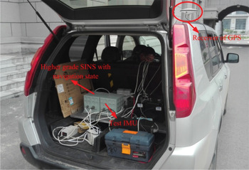
To verify the validity of the proposed alignment algorithm, a vehicle test was executed. The test vehicle was equipped with a differential GPS receiver and two different grades of Fibre Optic Gyroscope (FOG) SINSs as shown in Figure 9. The velocity error and location error of GPS were 0·05 m/s (Root Mean Square - RMS) and 0·1 m (RMS). The integrated navigation system with left side higher grade FOG SINS and GPS served as the benchmark for attitude, velocity and position, and provided the external reference speed V b for in-motion alignment. The integrated navigation system and the test IMU were fixed on a rigid aluminium alloy board, and the installation errors were also measured and compensated. In addition, the time synchronisation of the two systems is considered, and the time-delay is also compensated. The gyro constant drift and the accelerometer constant bias of the test IMU are less than 0·01°/h and 100 μ g respectively. The update frequency of GPS is 1 Hz. The local longitude and latitude were 126·6778° and 45·7778°, respectively.
The vehicle test.

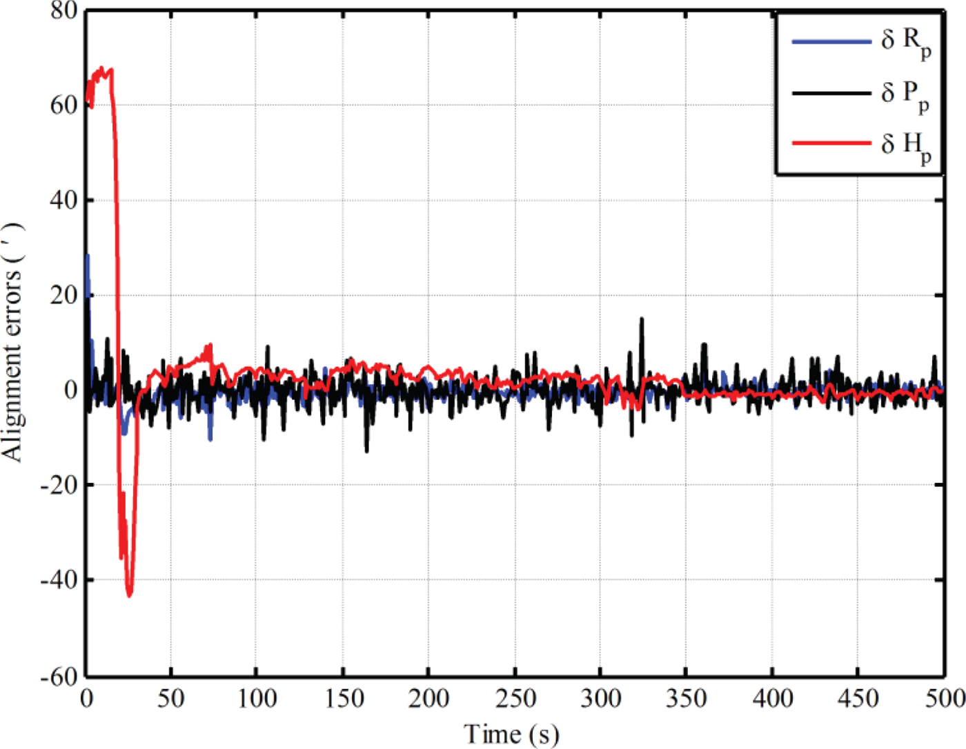
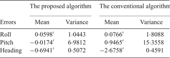
Firstly, fine alignment experiments based on the proposed model and the traditional one are conducted by intentionally adding initial attitude errors (1° for heading; 0·3° for both pitch and roll). Under the condition of the same smaller initial values of the noise matrix, the in-motion alignment with the conventional algorithm diverges. Therefore, the alignment results based on the traditional method are obtained by setting larger initial values of the noise matrix. The alignment results with pseudo-SINS modelling are obtained by transformation with the real time position in the e-frame from the integrated navigation system. The alignment results based on the two algorithms are shown in Figures 10 and 11. The statistics of alignment errors of the last 100 s are shown in Table 3.
The test results of initial alignment with conventional SINS modelling.

The test results of initial alignment with pseudo-SINS modelling.

Mean of alignment errors based on proposed algorithm at 85° latitude.

Comparing Figure 10 and Figure 11, the trends and oscillating processes of error curves of alignment are all similar. However, the heading alignment error with the traditional algorithm is larger than the one based on the proposed SINS modelling. The mean of heading alignment error of the last 100 seconds based on the two algorithms are
 $-0{\cdot}6941^{\prime}$
and
 $-2{\cdot}6758^{\prime}$
, respectively. As a result, the method of setting larger initial values of the noise matrix can maintain the KF performance, but at the expense of alignment accuracy. Moreover, the oscillation of level alignment error (roll and pitch errors) based on the traditional mechanisation is still larger, and the disturbances of level alignment errors are also more evident. The oscillation of the level alignment error with the pseudo-SINS modelling is still smaller, and the error curves are also smoother. In addition, from Table 3, the mean and variance of the alignment errors based on pseudo mechanisation are also smaller. As a result, the in-motion alignment with the pseudo-SINS modelling can improve the robustness of the alignment system. Therefore, the proposed SINS modelling has more advantages for in-motion alignment.
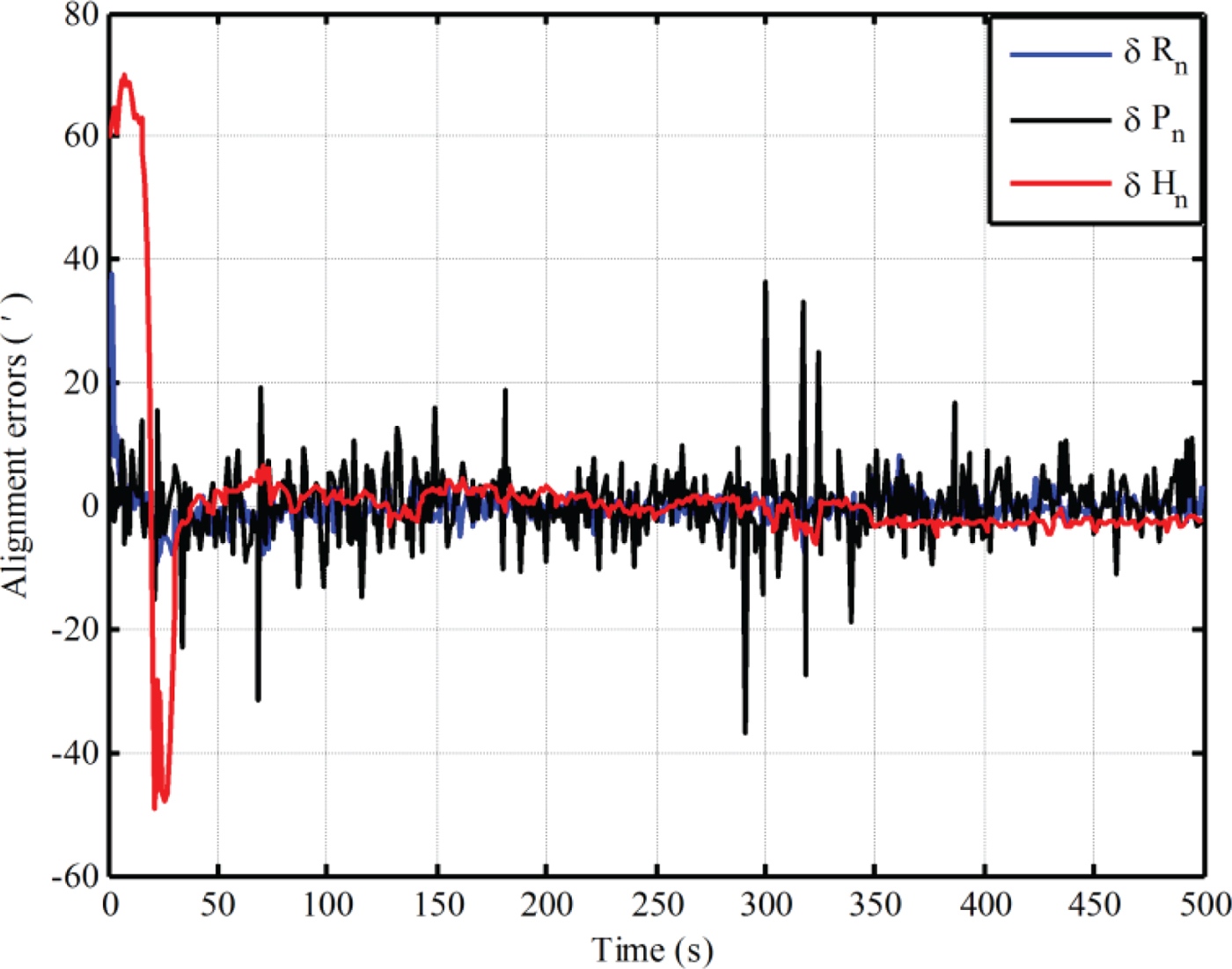
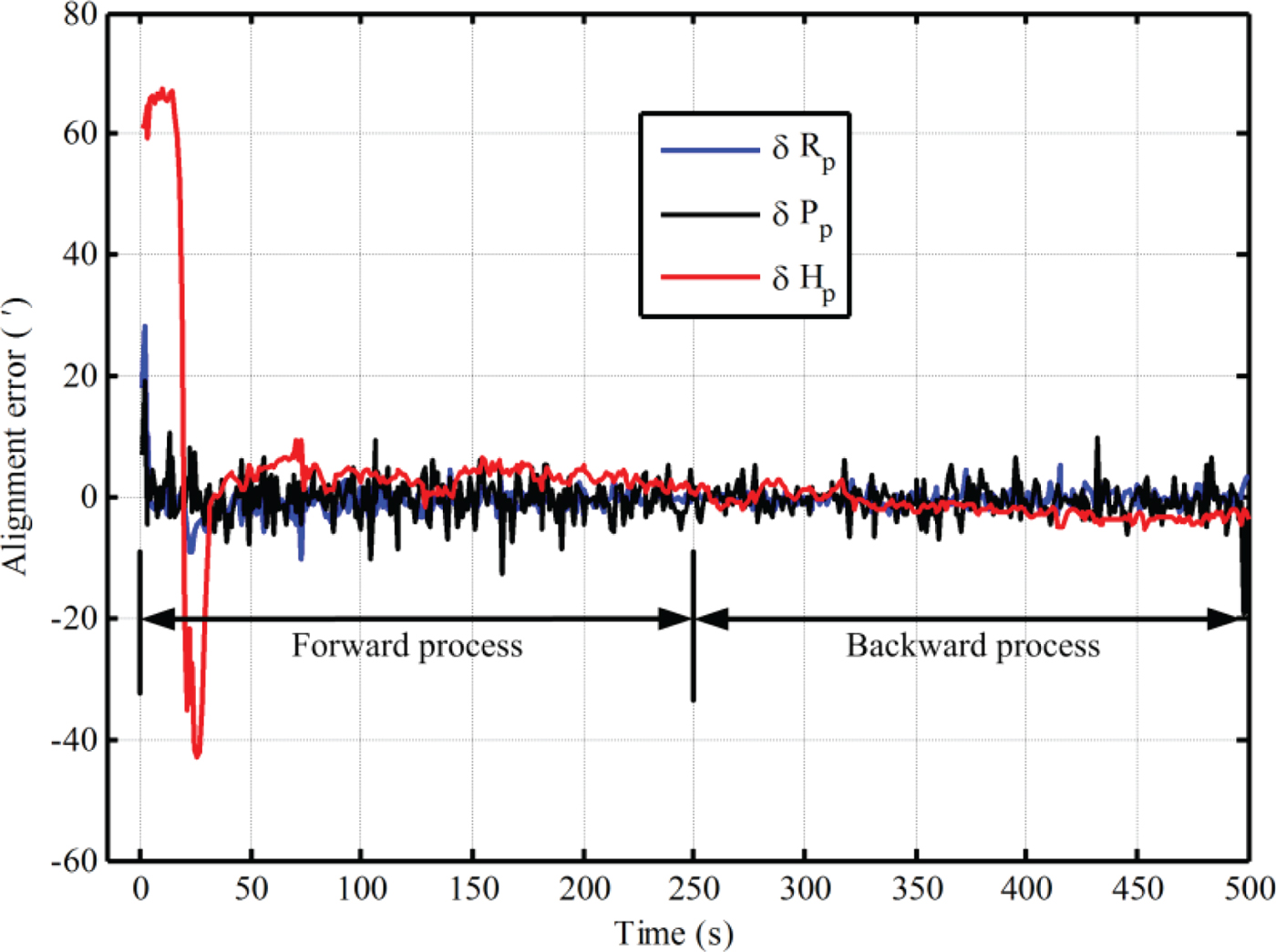
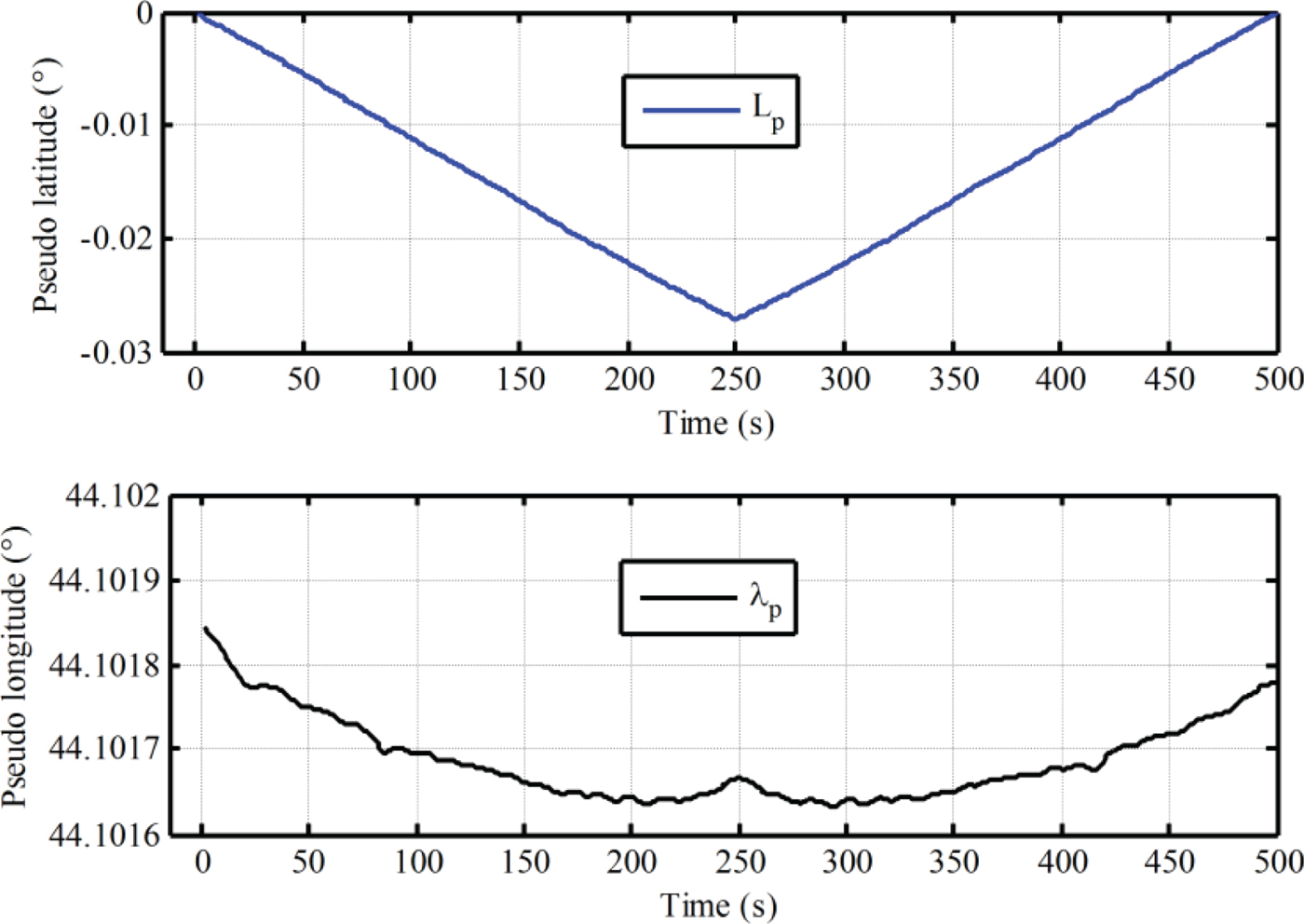
An in-motion alignment experiment based on the pseudo-SINS modelling and a backward process was also carried out, but only 250 s test data was used. The in-motion alignment test was achieved with a backward process, and the test results with the proposed algorithm are shown in Figures 12 and 13.
The test results of initial alignment based on pseudo-SINS modelling and a backward process.

The calculated pseudo-latitude and pseudo-longitude in the test process of alignment with the proposed algorithm.

As shown in Figure 12, the estimated errors of level misalignment angles and heading misalignment angle are convergent with time. Better alignment results are obtained with the proposed alignment algorithm. Moreover, from Figure 13, the calculated pseudo-latitude and pseudo-longitude returns to the initial position with a backward process. As a result, the pseudo-attitude matrix at the initial position is obtained at the end of the alignment phase. The initial attitude matrix relative to the g-frame can be obtained directly with Equation (21). This method has a less cumbersome derivation and low computational complexity, although some small drift errors of calculated pseudo-position are still unavoidable. This is because the external velocity information is selected as the observation information. The influence of drift errors of pseudo-position on the initial transformation matrix
 $C_{g}^{g_{p}} (0)$
is very small and can be neglected, since the initial pseudo-latitude is always zero. In conclusion, the proposed algorithm has superior performance compared with the traditional method.
7. CONCLUSION
In this paper, pseudo-SINS modelling associated with the backward algorithm is proposed to achieve velocity-aided in-motion alignment. The in-motion alignment is implemented with the pseudo-alignment model which is always equivalent to the traditional one in equatorial regions. As a result, the improved SINS modelling can eliminate the influence of alignment model on the performance of initial alignment caused by SINS modelling over the globe, and thus improve stability and robustness of the initial alignment and solve the problem of high latitude in-motion alignment caused by SINS modelling. The alignment accuracy of in-motion alignment based on a pseudo-alignment model is also analysed. The backward algorithm is proposed to obtain the pseudo-attitude matrix of the initial position at the end of initial alignment. Then, by initial transformation matrix, the initial attitude matrix in the e-frame can be obtained without sacrifice of alignment accuracy. The transformational computational complexity is also low and the backward process can still be used to accelerate the process of alignment. Finally, simulations and field experiments demonstrate the superior performance of the proposed method.
ACKNOWLEDGEMENTS
This work is supported by Ministry of Science and Technology of China (grant number 2014DFR10010)