1. Introduction
Flow choking presents a critical issue in supersonic ground effect flows (Li et al. Reference Li, Ning, Hou, Luo, Bo and Zhang2024) and inlet unstarting phenomena (Yue et al. Reference Yue, Jia, Xu, Zhang and Zhang2018; Saravanan et al. Reference Saravanan, Desikan, Francise and Kalimuthu2021; Jin et al. Reference Jin, Sun, Tan, Zhang and Huang2022; Tong et al. Reference Tong, Yue, Chen, Zhang and He2023). Under supersonic conditions, excessively low inflow Mach numbers or oversized contraction ratios induce choking within the inlet (Van Wie, Kwok & Walsh Reference Van Wie, Kwok and Walsh1996; Li et al. Reference Li, Qu, Li, Luo and Chen2025). Crucially, choked flow at the throat constitutes the primary mechanism for unstart (Yang et al. Reference Yang, Xie and Xu2024a , Reference Yang, Xie, Xu and Mab ), which significantly reduces captured mass flow rates while simultaneously amplifying total pressure losses, elevating aerodynamic drag, and inducing transient loads (Chang et al. Reference Chang, Li, Xu, Bao and Yu2017). Similarly, for supersonic vehicles in ground effect, the contracted passage between body and ground may develop choking (Li et al. Reference Li, Ning, Hou, Luo, Bo and Zhang2024). Under such choked conditions, substantial flow restructuring occurs, thereby severely degrading vehicle aerodynamics and stability. Precise quantification of the choked/unchoked transition boundary is therefore imperative.
The critical state between choked and unchoked flow is termed the choking limit (Im & Do Reference Im and Do2018), beyond which further reductions in Mach number or increases in contraction ratio will transition the flow from unchoked to choked states. There are two classical theories for determining choking in inlets at given contraction ratios: the isentropic limit (Veillard et al. Reference Veillard, Tahir, Timofeev and Molder2008) and the Kantrowitz limit (Kantrowitz Reference Kantrowitz1945). The isentropic limit postulates isentropic compression throughout the inlet, while the Kantrowitz limit assumes a normal shock at the contraction entry where incoming flow undergoes shock compression followed by isentropic acceleration to sonic speed at the throat. However, the complex shock structure in ground effect flows deviates significantly from the idealised configurations assumed in both theories, resulting in an actual choking limit Mach number (
 $M_{\textit{ch}}$
) that lies between the two theoretical predictions. Luo et al. (Reference Luo, Hou, Bo and Li2025)investigated choking characteristics in supersonic diamond airfoil ground effect flows, employing both isentropic and Kantrowitz limits to predict
 $M_{\textit{ch}}$
, yet their predictions exhibited non-negligible errors. This necessitates detailed investigation of shock structures specific to supersonic vehicle ground effect flows.
During supersonic ground effect flight, complex shock interaction phenomena occur in the flow field between vehicle and ground (Doig et al. Reference Doig, Barber, Leonardi, Neely and Kleine2010). Li et al. (Reference Li, Ning, Hou, Luo, Bo and Zhang2024) identified multiple shock structures in the near-ground flow field of a typical three-dimensional configuration, with significant variations in aerodynamic characteristics across different ground clearances. Doig et al. (Reference Doig, Barber, Leonardi, Neely and Kleine2008, Reference Doig, Wang, Kleine and Young2016) employed a twin-bullet model with symmetric arrangement to simulate ground effect in supersonic flow experiments. Their results demonstrated that shocks reflect off the symmetry plane and impinge on the bullet surfaces, with shock interaction locations and resultant flow structures varying with ground clearance. Doig (Reference Doig2014) also established the validity of inviscid flow assumptions for shock reflection studies in ground effect. For inviscid flows, shock reflection (Mach Reference Mach1878) configurations are categorised as regular reflection (RR) or Mach reflection (MR). The Neumann (Reference Neumann1943) and Von Neumann (Reference Von Neumann1945) criterion governs the RR-to-MR transition, while the three-shock theory provides analytical solutions for flow parameters near the triple point. Azevedo & Liu (Reference Azevedo and Liu1993) formulated the flow between the slip line and reflection surface through a quasi-one-dimensional isentropic approach, assuming linear slip line behaviour prior to expansion wave interactions, thereby deriving a Mach stem height model. Subsequent theoretical models for Mach stem height prediction were developed by Li & Ben-Dor (Reference Li and Ben-Dor1997) and Mouton & Hornung (Reference Mouton and Hornung2007). Gao & Wu (Reference Gao and Wu2010) and Bai & Wu (Reference Bai and Wu2017) investigated expansion wave effects on slip line curvature, establishing a refined Mach stem height model.
Extensive studies indicate that the ground clearance at the wedge trailing edge significantly influences shock reflection patterns (Vuillon, Zeitoun & Ben-Dor Reference Vuillon, Zeitoun and Ben-Dor1995; Baby, Paramanantham & Rajesh Reference Baby, Paramanantham and Rajesh2024; He & Shi Reference He and Shi2025). Vuillon et al. (Reference Vuillon, Zeitoun and Ben-Dor1995) investigated the effect of wedge aft clearance on shock reflection, proposing that the clearance at which the reflected shock impinges on the trailing edge defines the minimum ground clearance. Further reduction in clearance causes upstream Mach stem migration, ultimately forming a detached bow shock ahead of the wedge. Li & Ben-Dor (Reference Li and Ben-Dor1997) attributed this phenomenon to instability arising from interactions between the reflected shock, the rereflected shock on the wedge surface and the slip line, deriving an analytical formula for the minimum ground clearance related to the Mach stem height. These studies assume supersonic flow downstream of a straight reflected shock prior to expansion wave interactions. However, reflected shocks may exhibit curvature with subsonic downstream flow. Colella & Henderson (Reference Colella and Henderson1990) demonstrated that reflected shocks become curved as the inlet Mach number decreases. Through shock-polar analysis, Henderson & Lozzi (Reference Henderson and Lozzi1979) determined the free-stream Mach number at which sonic conditions occur downstream of the reflected shock. Similarly, Chow & Chang (Reference Chow and Chang1975) established criteria distinguishing supersonic and subsonic post-reflected-shock flows. Qin et al. (Reference Qin, Shi, Dowell, Pei and Huang2022) synthesised prior work to introduce the strong Mach reflection (sMR) concept, characterised by three features: (i) a non-uniform subsonic-to-supersonic transition region downstream of the reflected shock, (ii) a curved reflected shock and (iii) sonic flow (M = 1) at the intersection point of the reflected shock and the first expansion wave from the wedge trailing edge. When curvature develops in ground effect reflected shocks, the minimum clearance formula becomes inapplicable, necessitating new theoretical models for the choking limit that circumvent the influence of reflected shock curvature.
Given the identical leading-edge geometry between diamond airfoils and wedges, this study adopts a two-dimensional diamond airfoil as the research subject. To simplify the problem while retaining physical essence, we analyse supersonic ground effect flow structures under inviscid conditions. The results reveal that sMR occurs at the choking limit, with the reflected shock impinging on the lower vertex of the airfoil. Consequently, predicting the choking limit is reformulated as determining the free-stream Mach number at which the reflected shock strikes this vertex. By strategically selecting a control volume and solving its mass and momentum conservation equations, we circumvent the influence of reflected shock curvature. This approach establishes governing equations for the flow field under critical choking conditions, yielding a theoretical model to predict
 $M_{\textit{ch}}$
in supersonic ground effect flows.
Section 2 characterises the shock structure in diamond airfoil ground effect flows, analysing the influence of dimensionless ground clearance on flow configurations while benchmarking numerical simulations against one-dimensional theoretical predictions. Subsequent §§ 3 and 4 establish predictive models for
 $M_{\textit{ch}}$
in different scenarios, allowing predictions of
 $M_{\textit{ch}}$
at varied wedge half-angles and ground clearance heights. These models are rigorously validated through comparative analysis with numerical simulations and one-dimensional theories. The concluding § 5 synthesises key findings of this study.
2. Choking limits in two-dimensional ground effect flow
2.1. Flow structure of the two-dimensional ground effect flow field
The two-dimensional diamond airfoil studied herein is illustrated in figure 1, with chord length
 $c$
= 1 m, wedge half-angle
 $\theta$
and non-dimensional ground clearances defined as the trailing vertex clearance
 $H_t=h_t/c$
and leading-edge clearance
 $H_e=h_e/c$
. A coordinate system is defined with its origin at the leading-edge point O of the diamond airfoil, where the X-axis is horizontal and the Y-axis is vertical. Given the two-dimensional configuration of the flow, ground clearance is treated as the flow passage cross-sectional area; adopting the conventional inlet contraction ratio (
 $CR$
) concept to characterise airfoil proximity, this study defines
 \begin{equation} \left \{\begin{array}{l} \displaystyle \frac {1}{C R}=\frac {H_t}{H_e} ,\\ H_e=H_t+\displaystyle \frac {1}{2} \tan \theta .\end{array}\right . \end{equation}
Schematic of flow field parameters for a diamond airfoil in ground effect.

This study employs the finite volume method for numerical simulations using a density-based solver. Inviscid fluxes are computed via Roe’s scheme with shock capturing handled by the MUSCL scheme, assuming ideal gas behaviour. An implicit time-stepping method was employed to obtain the steady-state flow solution. The temporal discretisation was accomplished using the lower–upper symmetric Gauss–Seidel scheme to accelerate convergence. The computational domain utilises structured grids with boundary conditions configured as follows: far-field pressure at the inlet, back pressure at the outlet and no-penetration wall conditions on model surfaces. Further details regarding the numerical solver can be found in our previous work (Hu et al. Reference Hu, Jiang, Gao and Lee2018; Han et al. Reference Han, Hu, Jiang and Lee2024; Mo & Gao Reference Mo and Gao2024), while validation cases and a grid independence study are provided in Appendix A.
Numerical simulations were performed for diamond airfoils at wedge half-angle
 $\theta =10^{\circ }$
, non-dimensional ground clearance
 $H_t=0.5$
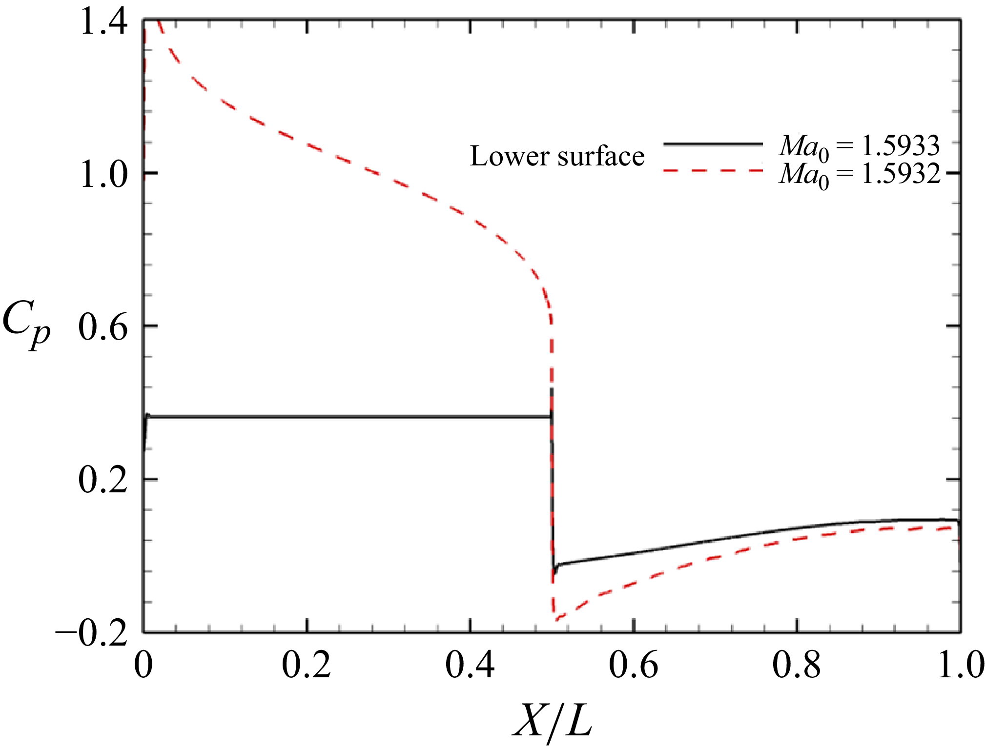
, zero angle of attack and varying free-stream Mach numbers under inviscid steady-state conditions. As shown in figure 2, The ground effect flow fields at
 $M_0=1.5932$
and
 $M_0=1.5933$
exhibit fundamentally different flow structures. For clarity, these are respectively termed the choked state (figure 2
a) and unchoked states (figure 2
b). In the choked state, a detached bow shock forms ahead of the airfoil. Downstream of this shock, the upper-surface flow reaches sonic speed immediately at the leading edge and undergoes sequential acceleration via expansion waves at both the leading-edge and maximum thickness locations. Conversely, the lower-surface flow remains subsonic after the bow shock passage, only attaining sonic speed at the maximum thickness position. Streamline analysis further reveals upstream flow spillage toward the upper surface near the leading edge. Figure 3 illustrates that the bow shock in choked conditions generates exceptionally high pressure coefficients on the lower surface near the leading edge, consequently producing a significant pitch-up moment. As depicted in figure 2(b), the unchoked state generates two oblique shocks at the airfoil leading edge. Beneath the airfoil, the entire flow passes through these shocks into the ground effect region without upper-surface spillage, forming a sMR comprising incident shock, reflected shock, Mach stem and slipline structures. The reflected shock is curved with subsonic flow downstream, impinging precisely on the airfoil’s lower vertex, where it generates a sonic line followed by expansion waves. Subsonic conditions persist downstream of the Mach stem, while the flow beneath the slipline approximates quasi-one-dimensional isentropic behaviour. Crucially, this vertex impingement configuration holds only near the choking limit; increasing the Mach number shifts the impingement point downstream. For clarity, we designate this near-choke flow state simply as ‘unchoked’.
Mach number contours of choked/unchoked ground effect flow fields at
 $H_t=0.5$
and (a)
 $M_0=1.5932$
, (b)
 $M_0=1.5933$
.

Pressure coefficient distribution on airfoil surface.

In unchoked flows, isentropic acceleration to sonic speed occurs downstream of the reflected shock, necessitating progressive pressure reduction along streamlines. The subsonic nature of this region permits upstream disturbance propagation, while downstream flow non-uniformity induces shock curvature. Parameters along the sonic line exhibit approximate uniformity because sonic line properties depend on free-stream conditions and total pressure loss along streamlines. Crucially, although the shock angle varies along the curved reflected shock, all solutions reside on the strong branch with uniform upstream flow at slightly supersonic Mach numbers. This results in minimal differences in total pressure loss across streamlines. Subsequent isentropic acceleration – a lossless process – then yields nearly identical pressure and density values for all streamlines upon reaching sonic conditions. Consequently, parameters are effectively uniform along the sonic line downstream of the reflected shock, justifying the assumption of consistent sonic line properties in subsequent modelling.
The physical mechanism underlying this drastic transition lies in the fact that the diamond airfoil and the ground form a two-dimensional, virtual nozzle with a convergent–divergent geometry. To satisfy mass conservation through the contracting cross-section, the local mass flux must increase, attaining a maximum at the sonic condition in the throat. Choking occurs when this maximum achievable mass flux at the throat is insufficient to pass the total incoming mass flow. Once the throat chokes, the resultant local pressure rise forces the triple point to propagate upstream along the incident shock. The upstream displacement of the shock system augments its total entropy rise, which in turn reduces the mass flux at the sonic condition, further intensifying the choking. This positive feedback loop ultimately ejects the entire shock system from the channel. The excess mass flow is then diverted over the leading edge, culminating in the deflection of the incoming flow and the formation of the detached bow shock.
In summary, the flow fields exhibit distinct characteristics between choked and unchoked states for diamond airfoils. The choked state is defined by a detached bow shock with upstream flow spillage, while the unchoked state features sMR comprising curved reflected shocks that impinge on the lower vertex, generating a sonic line with near-uniform flow parameters along its entire length.
2.2. Effect of
 $H_t$
on flow field structure

Ground clearance
 $H_t$
critically influences the flow structure by modulating the contraction ratio. To characterise its impact on both flow characteristics and the choking limit Mach number (
 $M_{\textit{ch}}$
), extensive numerical simulations were conducted over wide ranges of
 $M_0$
and
 $H_t$
. Critical Mach numbers distinguishing choked and unchoked states were obtained for
 $H_t$
= 0.2–0.8. Figures 4–9 present Mach number contour plots for both flow states at varying clearances. The choked state is characterised by two salient features: the formation of a detached bow shock upstream of the airfoil, and the deflection of the incoming flow. As a portion of the flow is unable to pass through the choked throat, it is deflected upward, detours around the leading edge and subsequently travels over the upper surface of the airfoil.
Mach number contours of choked/unchoked flow fields at
 $H_t=0.2$
and (a)
 $M_0=1.8513$
, (b)
 $M_0=1.8514$
.

Mach number contours of choked/unchoked flow fields at
 $H_t=0.25$
and (a)
 $M_0=1.7620$
, (b)
 $M_0=1.7621$
.

Mach number contours of choked/unchoked flow fields at
 $H_t=0.3$
and (a)
 $M_0=1.7129$
, (b)
 $M_0=1.7130$
.

Mach number contours of choked/unchoked flow fields at
 $H_t=0.4$
and (a)
 $M_0=1.5427$
, (b)
 $M_0=1.6428$
.

Mach number contours of choked/unchoked flow fields at
 $H_t=0.6$
and (a)
 $M_0=1.5562$
, (b)
 $M_0=1.5563$
.

Mach number contours of choked/unchoked flow fields at
 $H_t=0.8$
and (a)
 $M_0=1.5045$
, (b)
 $M_0=1.5046$
.

In unchoked flows, ground clearance
 $H_t$
significantly alters flow configurations. Distinct structures emerge across
 $H_t$
values: Mach stems are absent at
 $H_t$
= 0.2 and 0.25 but present at higher
 $H_t$
. Increasing
 $H_t$
elevates the Mach stem height and induces curvature. At ground clearance
 $H_t$
= 0.2, a RR occurs between the airfoil and ground, as shown in figure 4(b). The reflected shock manifests as a straight oblique shock with supersonic flow downstream, which constitutes the prerequisite for straight shock formation. This configuration exhibits uniform pre-shock flow and straight walls without curvature. The pressure gradient along streamlines arises primarily to satisfy throat mass flow requirements, necessitating Mach number variations immediately downstream of the reflected shock. Since disturbances cannot propagate upstream in supersonic flow, the Mach contours confirm uniform post-shock conditions, thereby validating both the shock straightness and its impingement on the lower vertex of the diamond airfoil.
When ground clearance increases to
 $H_t$
= 0.25, the flow structure at Mach features a curved reflected shock without Mach stem formation, corresponding to the strong solution (figure 5
b). This curvature occurs because subsonic flow downstream of the shock requires fluid acceleration to sonic speed at the throat to satisfy mass flux continuity. Given isentropic flow expansion downstream, pressure must decrease along streamlines, creating pressure gradients that propagate upstream to distort the shock. Consequently, the downstream Mach number serves as a diagnostic criterion: supersonic flow maintains straight shocks, whereas subsonic flow induces curvature. Figures 4–9 further confirm that the reflected shock consistently impinges on the lower vertex of the airfoil.
At
 $H_t$
= 0.3 (figure 6
b), the flow structure at
 $M_{\textit{ch}}$
exhibits a nearly straight Mach stem. At
 $H_t$
= 0.4 (figure 7
b), the structure exhibits an increased Mach stem height. For
 $H_t$
= 0.6 (figure 8
b) and 0.8 (figure 9
b), Mach stems develop with progressively larger heights and more pronounced curvature as ground clearance increases. Crucially, reflected shock attachment at the lower vertex persists universally across all clearances in unchoked states. As shown in figure 10, ground effect flow fields exhibit three distinct shock structures depending on ground clearance: RR, curved shock reflection and sMR. Regular reflection occurs at
 $H_t$
= 0.2. At
 $H_t$
= 0.25, a curved reflection shock forms without Mach stems. For clearances at
 $H_t=0.3{-} 0.8$
, Mach stems develop with progressively increasing height and curvature as
 $H_t$
rises. Crucially, reflection shock impingement on the airfoil lower vertex constitutes a fundamental characteristic of all unchoked field models.
Schematic diagram of the structural model of the ground effect flow field: (a) RR, (b) curved reflection and (c) MR.

Sonic line parameters.

Across all investigated cases, although the reflected shock exhibits curvature and the flow downstream displays non-uniform characteristics, the parameter variations along the sonic line remain negligible. As shown in figure 11, the flow parameters extracted along the sonic line segment between the airfoil lower vertex and the slip line demonstrate near-uniform distribution.
To assess viscous effects, supplementary simulations were performed for four cases (with
 $\theta =10^{\circ }$
and
 $H_t=0.3{-}0.6$
). The results show that the
 $M_{\textit{ch}}$
differs by less than 0.5 % between viscous and inviscid flows. The minimal influence of viscosity in this problem can be attributed to two primary reasons. First, in our supersonic ground effect scenario where the airfoil moves over a stationary ground, the viscous simulation set-up assigns the ground wall a velocity identical to the free stream, This effectively suppresses the formation of a ground boundary layer, thereby confining viscous effects to the airfoil surfaces only. Second, under the
 $p_0=101\,325$
Pa,
 $\rho _0=1.1768\,\rm kg\,m^{-3}$
,
 $T_0=300$
K inflow conditions of this study (
 $Re = 10^7$
), the boundary layer developing on the diamond airfoil remains very thin. Most importantly, it does not undergo significant shock-wave/boundary-layer interaction with the reflected shock. Owing to these factors, the influence of viscosity on the choking limit Mach number is confined to a very small range (
 ${\lt}0.5\,\%$
). Therefore, our subsequent investigation focuses on the theoretical prediction of the
 $M_{\textit{ch}}$
under inviscid conditions.
Viscous Mach number contours: (a)
 $H_t=0.3,M_0= 1.7204$
, (b)
 $H_t=0.4,M_0= 1.6486$
, (c)
 $H_t=0.5,M_0= 1.5967$
, (d)
 $H_t=0.6,M_0= 1.5604$
.

2.3. Effect of angle of attack
Based on the discussion of choking characteristics for diamond airfoils at zero angle of attack across various ground clearances in the preceding section, this study further investigates scenarios involving non-zero angles of attack. Our analysis demonstrates that these non-zero-angle-of-attack cases can be effectively transformed into equivalent zero-angle-of-attack problems.
As illustrated in figure 13(a), the diamond airfoil and the ground form a two-dimensional, converging–diverging nozzle. The occurrence of choking primarily depends on whether all the fluid entering this nozzle inlet can pass through the throat. Therefore, it is reasonable to conclude that the flow above the X-axis does not influence the choking phenomenon. Furthermore, our research indicates that the diverging section of the nozzle between the airfoil and the ground has a negligible effect on
 $M_ch$
, because once the flow passes the throat, choking cannot occur in the subsequent diverging section. Thus, we can deduce that the decisive factor for choking is the converging section, specifically the wall OR. When the diamond airfoil is at an angle of attack, the position and orientation of the compression wall OR change, as shown in figure 13(b). Based on this modified compression wall, we can conceptually define an equivalent diamond airfoils with zero angle of attack but with modified half-angle and chord length. The choking characteristics of the equivalent case are identical to those of the original airfoil at an angle of attack. The formulas for calculating the new half-angle and chord length are provided
 \begin{equation} \left \{\begin{array}{l} \displaystyle \theta _{new}=\theta +\alpha ,\\ c_{new}=\displaystyle \frac {\cos(\theta +\alpha )}{\cos\theta }c. \end{array}\right . \end{equation}
Schematic diagram of non-zero-angle-of-attack model.

To validate this conclusion, we performed additional simulations for two cases:
 $\theta =10^{\circ }$
, with
 $\alpha =2^{\circ }$
and
 $5^{\circ }$
. We first transformed these cases into their zero-angle-of-attack equivalents,
 $\theta =12^{\circ }$
and
 $15^{\circ }$
, while maintaining the same non-dimensional ground clearance of
 $H_t=0.5$
. We then numerically simulated the flow fields for all these configurations. The resulting choking limit Mach numbers and the corresponding Mach contours are presented and compared in figures 14 and 15.
Mach number contours for
 $\alpha =2^{\circ }$
: (a)
 $\theta =10^{\circ }, \alpha =2^{\circ }, M_0=1.6854$
, (b)
 $\theta =12^{\circ }, \alpha =0^{\circ }, M_0=1.6857$
, (c)
 $\theta =10^{\circ }, \alpha =2^{\circ }, M_0=1.6855$
, (d)
 $\theta =12^{\circ }, \alpha =0^{\circ }, M_0=1.6858$
.

The flow field contours clearly demonstrate that the key feature of the reflected shock impinging on the lower vertex persists even at non-zero angles of attack. Furthermore, both the Mach number contours and the choking limit Mach number for the non-zero-angle-of-attack cases are in excellent agreement with those of their equivalent zero-angle-of-attack cases. This close agreement validates the transformation of non-zero-angle-of-attack cases into equivalent zero-angle-of-attack cases. Consequently, it is fully justified for the subsequent theoretical investigation in this paper to focus on the choking limit Mach number of diamond airfoils at zero angle of attack.
Mach number contours for
 $\alpha =5^{\circ }$
: (a)
 $\theta =10^{\circ },\alpha =5^{\circ },M_0=1.8345$
, (b)
 $\theta =15^{\circ },\alpha =0^{\circ },M_0=1.8345$
, (c)
 $\theta =10^{\circ },\alpha =5^{\circ },M_0=1.8346$
, (d)
 $\theta =15^{\circ },\alpha =0^{\circ },M_0=1.8346$
.

2.4. Benchmarking numerical simulations against one-dimensional theory
Analogous to the starting Mach number in supersonic inlets,
 $M_{\textit{ch}}$
for ground effect flows should correlate with the contraction ratio, which is governed by
 $H_t$
and
 $\theta$
. Inviscid steady flow fields at varying contraction ratios were computed for
 $\theta = 5^\circ$
,
 $10^\circ$
and
 $15^\circ$
, as depicted in figure 16. Given the close resemblance between supersonic ground effect flows and internal flows within supersonic inlets, the choking phenomenon in ground effect scenarios exhibits strong similarity to inlet starting/unstarting behaviour. Comparative analysis of the Kantrowitz limit, isentropic limit and present numerical results partitions the parameter space into three distinct regions: the unstart zone below the isentropic limit, the self-starting zone above the Kantrowitz limit and the dual-solution region bounded by these two curves. The choking limit Mach number for two-dimensional airfoil ground effect flows resides within this dual-solution region.
Variation of choking limit Mach number with contraction ratio.

Both the Kantrowitz limit and the isentropic limit, as one-dimensional theoretical predictions for
 $M_{\textit{ch}}$
, exhibit certain discrepancies; this is primarily attributed to significant differences between the assumed flow field structures in these limits and the actual two-dimensional ground effect flow field. Within the two-dimensional ground effect flow field, a sMR is established, wherein the reflected shock impinges directly on the lower apex of the diamond airfoil. The total pressure loss incurred by the fluid passing through the incident and reflected shocks should be less than that caused by a normal shock, while the total pressure loss across the Mach stem is comparable to that of a normal shock. Consequently, the overall total pressure loss for the entire flow field lies between the scenarios of no loss and normal-shock loss; correspondingly,
 $M_{\textit{ch}}$
resides between the starting Mach numbers predicted by these two theoretical limits. When
 $\theta$
remains constant,
 $CR^{-1}$
depends solely on the
 $H_t$
. For larger
 $H_t$
values, the choking limit Mach number approaches the Kantrowitz limit more closely; this occurs because the increased ground clearance height corresponds to a taller Mach stem, resulting in greater overall total pressure loss within the flow field. Conversely, when
 $H_t$
decreases, the Mach stem diminishes in size, leading to reduced total pressure loss and a choking limit Mach number that shifts closer to the isentropic limit.
In the RR regime, straight reflection shocks enable calculation of
 $M_{\textit{ch}}$
using the canonical theoretical model. However, curved reflection shocks invalidate this theoretical model. Therefore, it is necessary to develop a new predictive model based on the specific shock structure inherent to ground effect flow fields.
3. Curved reflection choking limit theoretical model
In ground effect flow fields around diamond airfoils under critical choking conditions, the reflection shock impinges on the lower vertex of the diamond airfoil. Further reducing the free-stream Mach number (
 $M_0$
) causes upstream shock movement, triggering flow choking. Conversely, increasing the Mach number shifts the shock impingement point downstream. Therefore, predicting Mach reduces to determining
 $M_0$
at which the reflection shock precisely attaches to the lower vertex of the diamond airfoil.
Schematic of curved reflection flow field at choking limit.

When the reflection shock is curved, direct determination of the corresponding
 $M_0$
from geometric relationships becomes infeasible. The associated flow structure is illustrated in figure 17, with point R defined as the airfoil lower extremity. Following conventional notations, we use
 $\rho , p, V, a, \gamma$
to denote the density, pressure, velocity, sound speed and ratio of specific heats of the gas, respectively. Mach numbers at discrete spatial locations are annotated directly in the schematic, with numerical subscripts identifying specific points. All physical quantities share identical subscript conventions, denoting co-located parameters at the same spatial position. For instance: Mach number
 $M_2$
, pressure
 $p_2$
and density
 $\rho _2$
correspond to identical coordinates at region 2. We also use
 $\beta$
and
 $\theta$
to denote the shock angle and flow deflection angle across an oblique shock wave. Since the reflection shock is curved and its geometry remains unknown, direct computation of
 $M_0$
corresponding to shock impingement at point R is infeasible.
The non-uniform flow in region 3 precludes analytical solutions. However, mass conservation yields an integral formulation. By selecting the control volume
 $\varOmega$
bounded by the curved reflection shock, sonic line and reflection wall surface, the total mass flow entering through the reflection shock equals the total mass flow leaving across the sonic line. This specific selection is based on the following physical reasoning: first, the flow upstream of the curved shock is uniform. Consequently, the mass flux entering the control volume through the reflected shock depends solely on the relative coordinates of the shock’s start and end points, and is independent of the shock’s specific curvature. Second, the outlet boundary of the control volume is defined as the sonic line, where flow parameters (such as pressure and density) can be considered approximately uniform, thereby allowing the outflow mass flow rate to be determined. Although the control volume geometrically encloses a non-uniform region, the boundaries we have selected – the reflected shock in the uniform upstream flow and the approximately uniform sonic line – ensure that all necessary physical quantities for applying the integral conservation equations can be determined at these boundaries. Thus, the continuity equation for the control volume
 $\varOmega$
is established as follows:
 \begin{equation} \oint _{\partial \varOmega }\rho (\boldsymbol{V}\boldsymbol{\cdot }\boldsymbol{n}){\rm d}l=0, \end{equation}
where
 $\partial \varOmega$
is the closed boundary curves of
 $\varOmega$
,
 $\boldsymbol{n}$
is the outward-pointing unit normal vector and
 ${\rm d}l$
is the scalar differential element of arc length.
For oblique shock waves, the following classical shock relations hold:
 \begin{equation} M_2^2=f\left (M_0, \beta \right )\!, \displaystyle \frac {p_2}{p_0}=g\left (M_0, \beta \right ), \frac {\rho _2}{\rho _0}=h\left (M_0, \beta \right ), \tan \theta =S\left (M_0, \beta \right )\!, \end{equation}
where
 \begin{align} \left \{\begin{array}{l}f(M , \beta )=\displaystyle \frac {M ^2+\displaystyle \frac {2}{\gamma -1}}{\displaystyle \frac {2 \gamma }{\gamma -1} M ^2 \sin ^2 \beta -1}+\displaystyle \frac {M ^2 \cos ^2 \beta }{\displaystyle \frac {\gamma -1}{2} M ^2 \sin ^2 \beta +1} ,\\ g(M , \beta )=1+\displaystyle \frac {2 \gamma }{\gamma +1}\left (M ^2 \sin ^2 \beta -1\right ) ,\\ h(M , \beta )=\displaystyle \frac {(\gamma +1) M ^2 \sin ^2 \beta }{2+(\gamma -1) M ^2 \sin ^2 \beta }, \\ S(M , \beta )=2 \cot \beta \displaystyle \frac {M ^2 \sin ^2 \beta -1}{M ^2(\gamma +\cos 2 \beta )+2}.\end{array}\right . \end{align}
In this study, the reflection shock intersects expansion waves at point R, with the Mach number behind the reflection shock designated as
 $M_3 = 1$
. This specification stems from established findings that the post-interaction Mach number equals 1 at the intersection point between the reflection shock and the first expansion wave. Based on this fundamental condition, we determine the flow parameters at the initiation point of the sonic line. The specific formula is as follows:
 \begin{equation} M_3^2=f\left (M_2, \beta _2\right )\!, \displaystyle \frac {p_3}{p_2}=g\left (M_2, \beta _2\right ), \frac {\rho _3}{\rho _2}=h\left (M_2, \beta _2\right )\! . \end{equation}
We postulate that the total pressure loss is approximately equivalent across all streamlines traversing the reflection shock, allowing for the approximation of uniform flow properties along the sonic line, identical to the point R conditions. Furthermore, velocity vectors along the sonic line remain parallel to the reflection surface, with magnitudes computable via
 \begin{equation} \begin{aligned} & \left \{\begin{array}{l}V_2=E\left (M _2, p_2, \rho _2\right )\! ,\\ V_3=E\left (M _3, p_3, \rho _3\right ), \end{array}\right .\end{aligned} \end{equation}
where
 \begin{align} E(M , p, \rho )=M \sqrt {\gamma \frac {p}{\rho }}. \end{align}
The geometries of the reflection shock and sonic line remain unknown in this formulation. However, uniform conditions prevail both upstream of the reflection shock and along the sonic line itself. This dual uniformity renders the integral solution independent of shock and sonic line geometries. The governing parameter reduces exclusively to the ground clearance at point R. Integration of (3.1) provides the final form of this model
 \begin{equation} \frac {\sin (\beta -\theta )}{\sin \beta } \rho _2 V_2 H_t^{\prime }=\rho _3 V_3 H_t^{\prime }. \end{equation}
This equation can be solved inversely by postulating candidate Mach numbers within the range between the isentropic and Kantrowitz limits. For a given wedge half-angle
 $\theta$
, each assumed Mach number yields a computed ground clearance
 $H_t^{\prime }$
whose deviation from the actual clearance
 $H_t$
defines the height error. Iteration proceeds until the height error satisfies precision requirements, at which point the assumed Mach number constitutes the sought after
 $M_{\textit{ch}}$
.
As demonstrated in the figure 18 for
 $\theta =10^\circ$
at
 $H_t=0.23{-}0.25$
, theoretical predictions from this method show excellent agreement with numerical simulations, exhibiting relative errors below 1 %. However, this Mach-stem-free approach possesses a severely limited operational domain. At
 $H_t=0.3$
, where the Mach stem develops in the ground effect flow field, methodology extension becomes essential to accommodate flow fields containing Mach stems.
Choking limit Mach number versus ground clearance
 $H_t$
for curved reflection.

4. Mach reflection choking limit theoretical model
4.1. Flow structure model
Supersonic ground effect flow at the choking limit for a two-dimensional diamond-shaped airfoil is illustrated in figure 19, defining
 $H_t$
as the height from the lower vertex of the airfoil to the ground,
 $H_e$
as the frontal height from the leading edge to the ground and
 $H_0$
as the triple point height above ground. The flow domain is partitioned into distinct regions: region 1 occupies the zone ahead of the incident shock and Mach stem, while region 2 lies between the incident shock and the reflected shock. Isentropic acceleration develops downstream of both the reflected shock and the Mach stem. At the lower vertex of the airfoil, a sequence of expansion waves emanates, in which the first expansion wave constitutes the sonic line. Region 3 is bounded by this sonic line, reflected shock and slip line, where the sonic line is characterised by its vertical projection height
 $H_3$
and horizontal projection length
 $L_3$
. Perpendicular NM is drawn from the sonic line and slip line intersection to the ground, defining region 4 enclosed by the Mach stem, slip line, perpendicular NM and ground, with
 $H_4$
specifying the perpendicular NM height.
Regions 1–3 exhibit flow structures analogous to configurations in curved reflection. In prior studies of MR, region 4 was treated as quasi-one-dimensional flow; however, slip line deformation due to interaction with the expansion fan necessitates defining region 4 to isolate its influence. This study postulates that the segment ON of the slip line, prior to encountering the expansion fan, remains approximately rectilinear. Crucially, subsonic conditions prevail along perpendicular NM, necessitating
 $M_4$
computation via isentropic flow relations.
Schematic of MR flow field at choking limit: (a) height and region, (b) parameters at various locations, (c) close-up view of region 3.

Parameters near the triple point T are resolved via the three-shock theory. Shock relation equation (3.2) governs the incident shock, reflection shock and Mach stem. The incident shock admits the weak solution, while both the reflection shock and Mach stem require strong solutions due to subsonic post-shock flow downstream of the reflection shock. The governing equations are given by (4.1)
 \begin{equation} \left \{ \begin{aligned} &M_2^2=f\left (M_0,\beta \right ),\frac {p_2}{p_0}=g\left (M_0,\beta \right ),\frac {\rho _2}{\rho _0}=h\left (M_0,\beta \right ),\tan\theta =S\left (M_0,\beta \right ) ,\\ &M_{{T}3}^2=f\left (M_2,\beta _{{T}r}\right ),\frac {p_{{T}3}}{p_2}=g\left (M_2,\beta _{{T}r}\right ),\frac {\rho _{{T}3}}{\rho _2}=h\left (M_2,\beta _{{T}r}\right ),\tan\theta _{{T}3}=S\left (M_2,\beta _{{T}r}\right ), \\ &M_{{T}1}^2=f\left (M_0,\beta _{{T}m}\right ),\frac {p_{{T}1}}{p_0}=g\left (M_0,\beta _{{T}m}\right ),\frac {\rho _{{T}1}}{\rho _0}=h\left (M_0,\beta _{{T}m}\right ),\tan\theta _{{T}1}=S\left (M_0,\beta _{{T}m}\right ), \end{aligned} \right . \end{equation}
 \begin{equation} p_{{T}1}=p_{{T}3}. \end{equation}
Pressure continuity and identical velocity directions hold across the slip line. This yields (4.2), and the flow deflection angle formulas
 $\theta _{{T}1}=\theta -\theta _{{T}3}$
apply to standard three-shock configurations and
 $\theta _{{T}1}=\theta +\theta _{{T}3}$
for non-standard three-shock configurations.
Due to the curvature of the Mach stem, post-shock parameters differ between its upper and lower extremities. Parameters at the wall-attached end correspond to a normal-shock solution (4.3). Spatially averaged values across both extremities (4.4) provide representative inflow parameters for region 4
 \begin{equation} {M}_{\mathrm{G}}^2={f}\left ({M}_0,\frac {\pi }{2}\right )\!,\frac { {p}_{\mathrm{G}}}{{p}_0}={g}\left ({M}_0,\frac {\pi }{2}\right ),\frac {{\rho }_{\mathrm{G}}}{{\rho }_0}={h}\left ({M}_0,\frac {\pi }{2}\right )\!, \end{equation}
 \begin{equation} {M}_1=\frac { {M}_{{T}1}+ {M}_{\mathrm{G}}}{2},{p}_1=\frac { {p}_{{T}1}+ {p}_{\mathrm{G}}}{2},{\rho }_1=\frac { {\rho }_{{T}1}+ {\rho }_{\mathrm{G}}}{2}. \end{equation}
Similar to curved reflection scenarios, sonic line parameters require computation. We maintain the assumption of uniform sonic line properties but implement dual-point averaging at endpoints (points R and N) to reduce errors. Point R parameters inherit the curved reflection calculation methodology in (4.5), while point N parameters are computed via isentropic relations (region 3 isentropic flow). Critically, the velocity deflection angle
 $\theta _3$
along the sonic line equals the average of
 $\theta _{{R}}$
and
 $\theta _{{N}}$
, where
 $\theta _{{N}}$
approaches zero
 \begin{equation} \left \{ \begin{aligned}&M_3^2=f\left (M_2,\beta _{{R}}\right ),\frac {p_{{R}}}{p_2}=g\left (M_2,\beta _{{R}}\right ),\frac {\rho _{{R}}}{\rho _2}=h\left (M_2,\beta _{{R}}\right ),\tan\theta _{{R}}=S\left (M_2,\beta _{{R}}\right ),\\&M_3=1 ,\end{aligned}\right . \end{equation}
 \begin{equation} \begin{cases} \displaystyle \frac {p_{{N}}}{p_{{T}3}}=\chi (M_{{T}3},M_3)^{\gamma } ,\\ \displaystyle \frac {\rho _{{N}}}{\rho _{{T}3}}=\chi (M_{{T}3},M_3) ,\end{cases} \end{equation}
where
 \begin{align} \chi \left (M_1,M_2\right )=\left (\frac {2+(\gamma -1)M_1^2}{2+(\gamma -1)M_2^2}\right )^{\frac {1}{\gamma -1}}, \end{align}
 \begin{align} p_3=\frac {p_{{R}}+p_{{N}}}{2},\theta _3=\frac {\theta -\theta _{{R}}}{2}. \end{align}
However, three-shock theory solutions occasionally contradict experimental and numerical results – a discrepancy termed the von Neumann paradox. This phenomenon persists in ground effect flows over two-dimensional airfoils. As shown in figure 20, at
 $\theta =10^\circ$
and
 $M_{\textit{ch}}$
corresponding to clearances
 $H_t=0.3, 0.6$
and 0.8, the flow structures exhibit: standard MR at
 $H_t=0.3$
, non-standard MR at
 $H_t=0.6$
and three-shock theory violation at
 $H_t=0.8$
, where the reflected shock polar fails to intersect the incident shock polar.
Shock pole.

For configurations lacking triple-point solutions, we determine region 4 inflow conditions via the normal-shock solution, substituting sonic line parameters with point R parameters. The computational approach proceeds as follows:
 \begin{equation} {M}_1^2= {f}\left ( {M}_0,\frac {\pi }{2}\right ),\frac { {p}_1}{ {p}_0}= {g}\left ( {M}_0,\frac {\pi }{2}\right ),\frac { {\rho }_1}{ {\rho }_0}= {h}\left ( {M}_0,\frac {\pi }{2}\right )\!, \end{equation}
 \begin{equation} M_3^2=f\left (M_2,\beta _{{R}}\right ),\displaystyle \frac {p_3}{p_2}=g\left (M_2,\beta _{{R}}\right ),\frac {\rho _3}{\rho _2}=h\left (M_2,\beta _{{R}}\right ),\theta _3=\displaystyle \frac {\theta -\theta _{{R}}}{2}. \end{equation}
Region 4 is approximated as a quasi-one-dimensional isentropic flow following established literature. Given pressure continuity across the slip line, the pressure along MN equals that along the sonic line in region 3; all flow parameters are resolved through isentropic relations
 \begin{equation} \left \{ \begin{array} {l}\displaystyle \frac {p_{4}}{p_{1}}=\chi \left (M_{1},M_{4}\right )^{\gamma } ,\\ \displaystyle \frac {\rho _{4}}{\rho _{1}}=\chi \left (M_{1},M_{4}\right ),\\ p_4=p_3 .\end{array}\right . \end{equation}
4.2. Governing equations
All flow field parameters are now fully correlated with free-stream conditions, leading to the governing equations (4.12) to (4.16). By considering regions 3 and 4 as distinct control volumes
 $\varOmega _1$
and
 $\varOmega _2$
, the continuity and momentum conservation equations for each region are formulated, with the solution of these equation systems yielding
 $M_{\textit{ch}}$
 \begin{equation} \oint _{\partial \varOmega _1}\rho (\boldsymbol{V}\boldsymbol{\cdot }\boldsymbol{n}){\rm d}l=0, \end{equation}
 \begin{equation} \oint _{\partial \varOmega _2}\rho (\boldsymbol{V}\boldsymbol{\cdot }\boldsymbol{n}){\rm d}l=0, \end{equation}
 \begin{equation} \oint _{\partial \varOmega _2}\rho u(\boldsymbol{V}\boldsymbol{\cdot }\boldsymbol{n}){\rm d}l=-\oint _{\partial \varOmega _2}p(\boldsymbol{n}\boldsymbol{\cdot }\boldsymbol{i}){\rm d}l, \end{equation}
 \begin{equation} \oint _{\partial \varOmega _1}\rho u(\boldsymbol{V}\boldsymbol{\cdot }\boldsymbol{n}){\rm d}l=-\oint _{\partial \varOmega _1}p(\boldsymbol{n}\boldsymbol{\cdot }\boldsymbol{i}){\rm d}l, \end{equation}
 \begin{equation} \oint _{\partial \varOmega _1}\rho v(\boldsymbol{V}\boldsymbol{\cdot }\boldsymbol{n}){\rm d}l=-\oint _{\partial \varOmega _1}p(\boldsymbol{n}\boldsymbol{\cdot }\boldsymbol{j}){\rm d}l. \end{equation}
In the formulation,
 $\partial \varOmega _1$
and
 $\partial \varOmega _2$
denote the closed boundary curves of
 $\varOmega _1$
and
 $\varOmega _2$
.The velocity vector is decomposed as
 $\boldsymbol{V} = (u, v)$
, where
 $u$
and
 $v$
represent the X-axis direction velocity and the Y-axis direction velocity,
 $i$
and
 $j$
represent Cartesian unit vectors in the X and Y directions,
 $V_1$
denotes the post-Mach stem flow velocity,
 $V_2$
the fluid velocity in region 2,
 $V_3$
the velocity along the sonic line and
 $V_4$
the velocity along the vertical line. The velocities in each region can be expressed by the following equations:
 \begin{equation} \begin{cases} \boldsymbol{V}_{1}= {E}\left ( {M}_{1}, {p}_{1}, {\rho }_{1}\right ), \\ \boldsymbol{V}_{2}= {E}\left ( {M}_{2}, {p}_{2}, {\rho }_{2}\right ), \\ \boldsymbol{V}_{3}= {E}\left ( {M}_{3}, {p}_{3}, {\rho }_{3}\right ), \\ \boldsymbol{V}_{4}= {E}\left ( {M}_{4}, {p}_{4}, {\rho }_{4}\right ) .\end{cases} \end{equation}
Equation (4.12) represents the mass flow through the reflection shock into
 $\varOmega _1$
and mass flow across the sonic line out of
 $\varOmega _1$
. The mass flow through the reflection shock is simplified by computing the mass flow along perpendicular PT (where PT is the vertical segment connecting triple point T to the airfoil surface). This simplification yields (4.18)
 \begin{equation} (H_{e}-H_{0})\frac {\sin (\beta -\theta )}{\sin \beta }\rho _{2}V_{2}=(H_{3}\cos \theta _{3}-L_{3}\sin \theta _{3})\rho _{3}V_{3}. \end{equation}
Equation (4.13) represents the mass flow into
 $\varOmega _2$
through the Mach stem and the mass flow out of
 $\varOmega _2$
across perpendicular MN. During computation, the curved Mach stem is approximated as a vertical segment normal to the wall surface. Subsequent integration yields (4.19)
 \begin{equation} H_0\rho _1V_1=H_4\rho _4V_4. \end{equation}
In (4.14), the terms represent: the total X-component momentum influx into
 $\varOmega _2$
through the Mach stem surface, the total X-component momentum outflux from
 $\varOmega _2$
across perpendicular MN and the net X-component pressure force acting on
 $\varOmega _2$
boundaries (including the Mach stem, perpendicular MN and slip line surfaces), where neglecting viscous effects ensures the wall-contact force contributes no X-component force, with integration yielding (4.20)
 \begin{equation} p_{1}\gamma M_1^{2}H_{0}-p_{4}\gamma M_4^{2}H_{4}=p_{4}H_{4}-p_{1}H_{0}+\bar {p}(H_{0}-H_{4}), \end{equation}
where
 $\bar {p}$
denotes the mean pressure along the slip line, with
 $l_s$
representing the ON segment of the slip line, given by
 \begin{equation} \bar {p}=\frac {\int _{l_s}p{\rm d}l}{\int _{l_s}{\rm d}l}. \end{equation}
In (4.15), the terms represent: total X-component momentum influx into
 $\varOmega _1$
through the reflection shock surface, total X-component momentum outflux from
 $\varOmega _1$
across the sonic line surface and net X-component pressure force on
 $\varOmega _1$
boundaries (including reflection shock, sonic line and slip line surfaces), with integration yielding (4.22)
 \begin{equation} \begin{aligned} & p_2\gamma M_2^2\cos \theta \left (H_e-H_0\right )\displaystyle \frac {\sin (\beta -\theta )}{\sin \beta }-p_3\gamma M_3^2\cos \theta _3\left (\cos \theta _3H_3-\sin \theta _3L_3\right ) \\ & =p_3H_3-p_2\left (H_t-H_0\right )-\bar {p}\left (H_0-H_4\right ) .\end{aligned} \end{equation}
In (4.16), the terms represent: total Y-component momentum influx into
 $\varOmega _1$
through the reflection shock surface, total Y-component momentum outflux from
 $\varOmega _1$
across the sonic line surface and net Y-component pressure force on
 $\varOmega _1$
boundaries (including reflection shock, sonic line and slip line surfaces), with integration yielding (4.23)
 \begin{equation} \begin{aligned} & p_2\gamma M_2^2\sin \theta \left (H_e-H_0\right )\frac {\sin \left (\beta -\theta \right )}{\sin \beta }-p_3\gamma M_3^2\sin \theta _3\left (\cos \theta _3H_3-\sin \theta _3L_3\right ) \\ & =\bar {p}\left (\frac {1}{2}-\frac {H_e-H_0}{\tan \beta }+L_3\right )-p_2\left (\frac {1}{2}-\frac {H_e-H_0}{\tan \beta }\right )-p_3L_3 .\end{aligned} \end{equation}
After simplification, the system comprises five equations with five unknowns. By solving the coupled equations (4.18) to (4.23), we determine the height of the Mach stem
 $H_0$
, height of the sonic line
 $H_3$
, length of the sonic line
 $L_3$
, height of the perpendicular MN
 $H_4$
and average pressure on the slip line
 $\bar {p}$
, with results as follows:
 \begin{equation} \left \{ \begin{aligned} &\bar {p}=\frac {{p}_{1}\gamma {M}_{1}^{2}-{p}_{4}\gamma M_{4}^{2}E+{p}_{1}-{p}_{4}{E}}{1-{E}} ,\\&H_0=\frac {D-\left (\displaystyle \frac {\left (A+B+C\right )\left (K-p_2\right )}{p_3-K}+\left (A+B\right )\right )\displaystyle \frac {\tan \theta }{2}}{\left (\displaystyle \frac {\left (A+B+C\right )\left (K-\bar {p}\right )}{p_3-K}+\left (A+B\right )\right )\left (E-1\right )} ,\end{aligned} \right . \end{equation}
where
 \begin{align} \begin{cases} {K}=p_{2} {\gamma } {M}_{2}^{2}\cos \theta \displaystyle \frac {\sin( {\beta }- {\theta })}{\sin {\beta }}-p_{3} {\gamma } {M} _{3}^{2}\cos \theta _{3}\displaystyle \frac {\sin( {\beta }- {\theta })}{\sin {\beta }}\displaystyle \frac { {\rho }_{2}V_2}{ {\rho }_{3}V_3}+ {p}_{2}, \\ {A}=p_{2} {\gamma } {M}_{2}^{2}\sin \theta \displaystyle \frac {\sin( {\beta }-\theta )}{\sin {\beta }}-p_{3} {\gamma } {M}_{3}^{2}\sin \theta _{3}\frac {\sin( {\beta }- {\theta })}{\sin {\beta }}\frac { {\rho }_{2}V_2}{ {\rho }_{3}V_3}+\displaystyle \frac { \bar {p}- {p}_{2}}{ {\tan} {\beta }} ,\\ {B}=\left (\bar {p}-p_{3}\right )\displaystyle \frac {\sin( {\beta }-\theta )}{\sin {\beta }}\frac { {\rho }_{2}V_2}{ {\rho }_{2}V_2\sin \theta _{3}}, \\ {C}=\displaystyle \frac { {p}_{3}-\bar {p}}{ {\tan} {\theta }_{3}} ,\\ {D}=\displaystyle \frac { { \bar {p}-{p}_{2}}}{2} ,\\ {E}=\displaystyle \frac { {\rho }_{1} {V}_{1}}{ {\rho }_{4} {V}_{4}} .\end{cases} \end{align}
Through additional simplifications, both
 $H_0$
and
 $\bar {P}$
become expressible through known parameters, where coefficients
 $K$
,
 $A$
,
 $B$
,
 $C$
,
 $D$
and
 $E$
are introduced to streamline expressions and
 $H_3$
,
 $L_3$
and
 $H_4$
reduce to functions solely dependent on the
 $H_0$
. This enables calculation of the airfoil-to-ground clearance at the lower extremity
 $H_t^{\prime }$
 \begin{equation} H_3=\frac {(K-\bar {p})(1-E)H_0+(p_2-K)\displaystyle \frac {\tan \theta }{2}}{K-p_3}, \end{equation}
 \begin{equation} L_3=\frac {H_3}{\tan \theta _3}-(H_e-H_0)\frac {\sin (\beta -\theta )}{\sin \beta }\frac {\rho _2V_2}{\rho _3V_3\sin \theta _3}, \end{equation}
 \begin{equation} H_4=EH_0, \end{equation}
 \begin{equation} H_t^{\prime }=H_3+H_4. \end{equation}
Given free-stream conditions
 $p_0,\,\rho _0$
and wedge half-angle
 $\theta$
, an appropriate
 $M_0$
(between isentropic and Kantrowitz limits) is assumed. Classical oblique shock relations compute the flow parameters in the uniform region 2. Normal-shock relations determine the flow parameters at point G at the foot of the Mach stem. The existence of a triple-point solution is evaluated based on the incoming flow conditions. Where present, triple-shock theory resolves the flow parameters near the triple point. Parameters near the triple point in region 4 and those at point G are averaged to define the inlet parameters for region 4. Parameters near the triple point in region 3 determine point N properties via isentropic relations. The condition
 $M_3$
= 1 at the airfoil lower vertex yields point R parameters. The averaged values of points R and N define the sonic line parameters. Finally, isentropic relations compute the parameters along the vertical line MN. Where no triple-point solution exists, point G parameters directly define the region 4 inlet conditions and point R parameters define the sonic line parameters, with all other computational procedures remaining unchanged. With all boundary parameters of the
 $\varOmega _1$
and
 $\varOmega _2$
thus established, substitution into the governing equations (4.24)–(4.29) yields the computed height
 $H_t^{\prime }$
. If
 $H_t^{\prime }$
exceeds the given ground clearance
 $H_t$
, the assumed
 $M_0$
is too small; conversely, if
 $H_t^{\prime }$
is less than
 $H_t$
,
 $M_0$
is too large. Iterative refinement continues until
 $H_t^{\prime }=H_t$
, at which point the corresponding
 $M_0$
defines the sought choking limit Mach number
 $M_{\textit{ch}}$
.
4.3. Model verification and comparison
The theoretical model developed in this work is strictly valid only under the assumptions of two-dimensional, steady, inviscid flow over a smooth rigid ground surface. The predictive methodology for choking limit Mach number in supersonic two-dimensional airfoil ground effect flows developed within this study determines the choking limit Mach number given the diamond airfoil wedge half-angle and ground clearance. Validation of the theoretical model applicability across diverse diamond airfoils involved computations at
 $\theta =5^\circ$
,
 $10^\circ$
and
 $15^\circ$
. Figure 21 compares predictions from the present methodology against CFD simulations, the isentropic limit and the Kantrowitz limit. Conventional models exhibit significant deviations from numerical results, while the present methodology shows strong agreement with CFD data: prediction errors remain below 3 % across all ground clearances at
 $\theta =5^\circ$
and
 $10^\circ$
. For the
 $\theta =15^\circ$
case, the maximum errors stay under 3 % at
 $H_t$
between 0.3 and 0.7, reaching 3.31 % only at
 $H_t=0.8$
. The primary error source stems from increasingly pronounced Mach stem curvature at larger ground clearances. Our method assumes a straight Mach stem segment, neglecting the y-direction pressure term on the Mach stem in the momentum equations. This omitted term grows with curvature, amplifying errors at greater ground clearances. Nevertheless, overall errors remain acceptable. On the other hand, a kink emerges in the prediction curve at
 $H_t=0.8$
for the
 $\theta =10^\circ$
case. This discontinuity primarily arises because triple-point solutions are absent under this condition, requiring substitution of post-Mach stem parameters using normal-shock relations. The model transition triggers the abrupt curve variation, while no such shift occurs at
 $\theta =5^\circ$
and
 $10^\circ$
. These results collectively confirm methodology robustness for various diamond airfoils. The solution process simultaneously resolves the Mach stem height. At smaller ground clearances, mathematically negative height values may emerge, indicating operation beyond the model validity domain. This methodology applies strictly to configurations with positive Mach stem height.
Choking limit Mach number versus ground clearance
 $H_t$
for MR.

Choking limit Mach number prediction: theory versus numerical simulations.

The
 $CR^{-1}{-}M_{\textit{ch}}$
plane contains a family of choking limit boundaries (figure 22), each uniquely associated with a semi-wedge angle
 $\theta$
. For any
 $\theta$
, the characteristic curve
 $M_{\textit{ch}}(CR^{-1})$
delineates the critical transition: below this boundary, flow choking initiates either when
 $M_0$
decreases below
 $M_{\textit{ch}}(h_t)$
at fixed ground clearance
 $H_t$
, or when
 $H_t$
reduces below the critical height at fixed Mach number.
5. Conclusions
This study investigates supersonic ground effect flows around two-dimensional diamond airfoils, elucidating flow configurations, ground clearance effects on shock structures and choking limit flow characteristics. A novel method for predicting choking limit Mach numbers is proposed. The primary contribution lies in identifying curved reflected shocks in ground effect flows and developing a control-volume approach solving mass and momentum conservation equations. By leveraging uniform pre-shock properties and homogeneous sonic line parameters, this method circumvents complications from reflected shock curvature and sonic line curvature, significantly enhancing prediction accuracy. Key conclusions are:
-
i. Choked and unchoked flows exhibit fundamentally distinct features: choked flows feature detached bow shocks and upstream spillage, while unchoked flows manifest three configurations with increasing ground clearance
$H_t$
– RR at small
$H_t$
, curved reflection without Mach stems at moderate
$H_t$
and sMR at larger
$H_t$
. In curved reflection and sMR cases, reflected shocks curve with subsonic downstream flow. Crucially, across all
$H_t$
values, reflected shocks impinge on the lower vertex of the airfoil, generating a sonic line with near-uniform parameters. Choking limit Mach numbers decrease as
$H_t$
increases. -
ii. Although the reflected shock is curved and the flow downstream is non-uniform, key parameters such as the pressure coefficient and density along the sonic line at the throat exhibit minimal variation.
-
iii. Choking limit Mach numbers for diamond airfoils lie between the isentropic and Kantrowitz limits. At fixed
$\theta$
, larger
$H_t$
increases Mach stem height and total pressure loss, shifting predictions toward Kantrowitz limits; smaller
$H_t$
reduces Mach stem height and total pressure losses, aligning results with isentropic limits. -
iv. The proposed model transforms choking limit prediction into determining the free-stream Mach number at reflected shock impingement on the lower vertex. Two control volumes are defined:
$CV_1$
(bounded by reflected shock, sonic line, slip line) and
$CV_2$
(enclosed by Mach stem, slip line, vertical line and ground). Solving conservation equations for these volumes yields choking limit Mach numbers. Uniform properties upstream of the reflected shock and along the sonic line, respectively, eliminate the influence of reflected shock curvature and sonic line curvature in this model, requiring only relative endpoint coordinates. Validation shows maximum errors of 3 % for
$\theta =5^\circ ,10^\circ$
and 3.31 % for
$\theta =15^\circ$
across all
$H_t$
values, demonstrating high-fidelity predictions for diverse diamond airfoils. This method enables rapid assessment of choking phenomena and supports ground effect vehicle design.


Funding
This work was jointly supported by National Natural Science Foundation of China (12472233,12402384), Beijing Municipal Science & Technology Commission and Administrative Commission of Zhongguancun Science Park (Z241100005424001) and Fundamental Research Funds for the Central Universities
Declaration of interests
The authors report no conflicts of interest.
Appendix A. Computational fluid mechanics method
The wind tunnel experimental data and numerical results of Doig et al. (Reference Doig, Wang, Kleine and Young2016) on the supersonic projectile ground effect serve as the validated benchmark for the numerical methodology in this study. Although detailed geometric parameters of the projectile model are not provided by Doig, these have been reported by Lang et al. (Reference Lang, Connolly, Boer, Shahpar, Hinchliffe and Gilkeson2024). This study employs an identical projectile geometry to that used by Lang et al. (Reference Lang, Connolly, Boer, Shahpar, Hinchliffe and Gilkeson2024), with a bullet length
 $l=120\rm\,mm$
, diameter
 $d=42.6\rm\,mm$
and ground clearance
 $h=0.5d$
. The computational domain is illustrated in figure 23. A density-based steady solver is adopted, utilising a second-order discretisation scheme for convective terms and the SST
 $k-\omega$
turbulence model. The free-stream Mach number is set to 1.1. All other inflow parameters and mesh counts are consistent with those reported by Doig et al. (Reference Doig, Wang, Kleine and Young2016). The computed surface pressure coefficient distribution of the projectile is presented in figure 24. Results show good agreement between the present simulation and the numerical data of Lang et al. (Reference Lang, Connolly, Boer, Shahpar, Hinchliffe and Gilkeson2024), while a minor discrepancy is observed relative to the results of Doig et al. (Reference Doig, Wang, Kleine and Young2016). This deviation is primarily attributed to differences in the projectile geometry specifications provided by Lang et al. (Reference Lang, Connolly, Boer, Shahpar, Hinchliffe and Gilkeson2024). The consistency with Lang et al. (Reference Lang, Connolly, Boer, Shahpar, Hinchliffe and Gilkeson2024) validates the accuracy of the current numerical methodology.
Schematic diagram of the computing domain.

Pressure coefficient curve of the projectile surface and comparison with the experimental and numerical results of Doig et al. and the numerical data of Alex J. Lang et al.

A grid independence study for the present investigation is presented below. We employ structured grids for the computational domain. To verify grid convergence, three distinct mesh resolutions – coarse, medium and fine – were constructed with identical topological structure, as illustrated in figure 25. Given that the choking characteristics of diamond airfoils in ground effect are primarily governed by the flow region between the airfoil and the ground, selective grid refinement was applied exclusively to this critical zone while maintaining consistent mesh density in the remaining areas. A grid convergence study was conducted at
 $M_0=1.6,\theta =10^{\circ },H_t=0.5$
. The pressure coefficient along the airfoil lower surface was adopted as the evaluation metric. As shown in the figure 26, the results indicate noticeable oscillations in the pressure distribution computed with the coarse mesh, while the medium and fine meshes exhibit excellent agreement. Consequently, the medium mesh resolution was selected for all subsequent investigations. A consistent grid strategy – maintaining identical cell counts and block topology – was applied across all combinations of half-wedge angles and ground clearances.
Grid topology and quantity.

Computed results: (a) density gradient contours at medium mesh, (b) wall pressure coefficient distributions across three mesh resolutions.