I. INTRODUCTION
Recently, the long-term evolution (LTE) system [1] is a major technological advance in mobile communication and has received much attention due to significantly higher data rate than that of 3 G wireless wide area network (WWAN) operations. To embed into a limited space in a 4 G mobile device and fulfill the bandwidth specifications of 698–960/1710–2690 MHz bands, planar printed monopole antenna (MA) is the optimal candidate with the compact profile and their multi-band operation capability. However, with the defect of greater dimension, several planar internal mobile phone antennas (MAs) have been presented for LTE/WWAN operation [Reference Ku, Liu and Ding2–Reference Ban, Liu, Li, Guo and Kang14]. Meanwhile, due to the trend of thinner thickness, slim profile has become popular for the handsets, especially for the smartphones. Therefore, by accommodating the battery inside the rectangular notch of the system circuit board to decrease the total required thickness of the handsets, this study firstly proposes dual parasitic shorted strips to generate dual 0.25-wavelength resonant modes at approximately 798/940 MHz bands to cover the LTE700/GSM850/900 operating bandwidth. Then, a modified F-shaped monopole strip is utilized to excite a resonant mode in the upper (1710–2690 MHz) band of the desired antenna and fed with a C-shaped ground plane [Reference Lu and Guo15] devised to enhance the operating bandwidth of an antenna disposed on the shaped system circuit board, which is larger than that disposed on the traditional simple system circuit board. As for the overall antenna volume of 35 × 10 × 0.8 mm3, the proposed MA has the same dimension as that of the internal mobile phone antenna [Reference Lu and Guo15]; however, with the simpler antenna structure. Therefore, the proposed design is more easily to be manufactured and embedded into a mobile phone. This paper is organized as follows: the design concept of the proposed MA is described in Section II, and Section III presents the results of performance tests of the proposed antennas, including both simulation results and actual measurement data. Simulation results related to antenna performance, e.g. operating bandwidth and antenna gain, are also discussed. Finally, Section IV summarizes the findings and conclusions of the study. Details of the proposed antenna design and experiment results are presented and discussed in related sections.
II. ANTENNA DESIGN
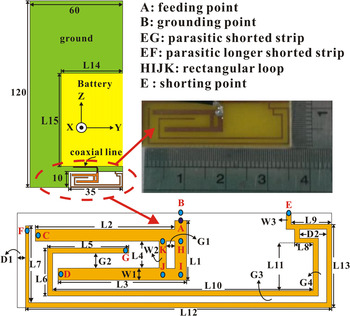
Figure 1 shows the geometrical configuration of the proposed small-size monopole antenna. To make it more promising for practical slim handset application, the rectangular notch with the size of L14 × L15 is utilized to suitably embed a battery with the connection at proper positions to the ground plane of the C-shaped circuit board. Meanwhile, the antenna is printed on the same side of an FR4 substrate with the dimension of 35 × 10 × 0.8 mm3 and mounted along the bottom-right edge of the C-shaped system ground with the dimension of 120 × 60 × 0.8 mm3. In this study, an F-shaped driven monopole with the end points at points C and D is introduced and coupled with dual parasitic monopole strips shorted at point E. A 50 Ω mini coaxial line is utilized to connect at the feeding point (point A) of the F-shaped driven monopole and the system grounding point (point B). First, the resonant modes operating at 722/1810 MHz bands (modes I and IV in Fig. 2) with half- and one-wavelength surface current distribution, respectively, are excited along the rectangular notch's edge of the C-shaped ground plane from the shorted point E to the end edge of the system ground. Then, the quarter-wavelength resonant mode (mode II) at near 798 MHz band is excited by the lower meandered arm (section EF) of dual parasitic shorted strips. Moreover, to enhance the impedance bandwidth of the lower band, the upper meandered arm (section EG) is introduced to generate 940 MHz band (mode III). Next, the F-shaped driven strip is arranged as a quarter-wavelength monopole to generate the fundamental resonant mode (mode V) close to 2300 MHz. To optimize the proposed antenna, a commercially available software package, Ansys HFSS, based on the finite element method [16], is utilized according to the above guidelines. The return loss (RL) and input impedance of the proposed MA were measured with an Agilent N5230A vector network analyzer. Figure 1 displays the design parameter values obtained by the above strategy. Moreover, those results are simultaneously optimized using Ansys HFSS as the following parameters are set: L1 = 6.5 mm, L2 = 15.9 mm, L3 = 14.3 mm, L4 = 2.9 mm, L5 = 9 mm, L6 = 5.2 mm, L7 = 8.5 mm, L8 = 2 mm, L9 = 4.5 mm, L10 = 29 mm, L11 = 5.2 mm, L12 = 34 mm, L13 = 9 mm, L14 = 40 mm, L15 = 60 mm, W1 = 1.3 mm, W2 = 1 mm, W3 = 0.5 mm, G1 = 1 mm, G2 = 1.7 mm, G3 = 0.8 mm, G4 = 1 mm, D1 = 1 mm, and D2 = 3 mm.
Geometry and photograph of the proposed printed MA for slim mobile phone application.

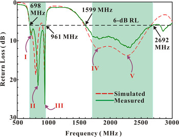
Simulated and measured RL against frequency for the proposed planar monopole antenna.

III. RESULTS AND DISCUSSIONS
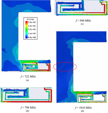
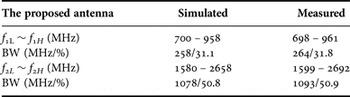
Figure 2 summarizes the simulation and experimental results for RL in the proposed monopole antenna. Table 1 compares the related results, indicating a satisfactory correlation for the proposed planar monopole antenna operating at the LTE/WWAN bands in a slim mobile phone. The lower band reveals a 3:1 voltage standing wave ratio (6 dB RL) and a bandwidth of 263 MHz (698–961 MHz), whereas the higher band has a bandwidth of 1093 MHz (1599–2692 MHz). Dual widebands can comply with the bandwidth requirements of the desired eight-band LTE/WWAN (LTE700/GSM850/900/GSM1800/1900/UMTS/LTE2300/2500) operations. We can find that the first resonant mode in the lower band can be excited using the rectangular notch to enhance the operating bandwidth, which is similar to that in [Reference Lu and Guo15]. To completely introduce the operation of the proposed monopole antenna, Fig. 3 shows the simulated surface current distributions on the C-shaped system ground, the F-shaped driven monopole and dual parasitic shorted strips at typical frequencies. First, the surface current distribution along the rectangular notch's edge of the C-shaped ground plane is excited at its fundamental mode at 722 MHz with a 0.5 wavelength surface current distribution. Then, in Fig. 3(b), the surface current at 798 MHz is distributed along the lower meandered arm (section EF) of dual parasitic shorted strips, which is excited with a 0.25 wavelength surface current distribution having a maximum strength at point E and decreasing to be generally null at the end of the shorted strip (point F). Next, Fig. 3(c) illustrates the fundamental mode is excited at 940 MHz with maximum strength along the upper shorted strip (section EG) of dual parasitic shorted strips. Finally, at the 1810 MHz band, a null point is found along the rectangular notch of the C-shaped system ground, indicating that the first operating mode of the upper band is the higher-order mode of the first resnant mode in the lower band.
Simulated surface current distributions on the major metal pattern of the proposed printed monopole antenna. (a) f = 722 MHz. (b) f = 798 MHz. (c) f = 940 MHz. (d) f = 1810 MHz.

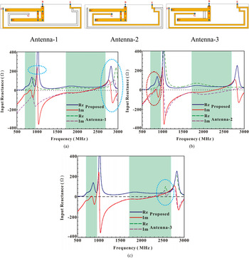
Moreover, the operating principles of the proposed small-size printed MA are examined. Figure 4 compares the simulated input impedance for various antenna structures with the modified F-shaped coupled-fed or dual parasitic shorted strips. For Antenna-1 case, without the upper monopole (section EG) of dual parasitic shorted strips, the resonant mode at 940 MHz can be not excited to make the operating bandwidth narrower. Similarly, Fig. 4(b) shows that the resonant mode at about 798 MHz band cannot be easily excited without the lower arm (Antenna 2) of dual parasitic shorted strips. Additionally, according to our results of Fig. 4(c), we find that the resonant mode at about 2600 MHz band can be excited for the conventional F-shaped driven monopole (Antenna 3), however, with worse antenna efficiency. Therefore, in this study, by introducing section KJ into the F-shaped monopole to have a loop monopole, the peak gain and antenna efficiency of this proposed planar MA can be enhanced with little variation across the higher operating band.
Comparison of the simulated input impedance for the cases without the upper monopole (Antenna 1) and the lower-arm (Antenna 2) of dual parasitic shorted strips and the case without the section KJ of the modified F-shaped driven monopole strip (Antenna 3).

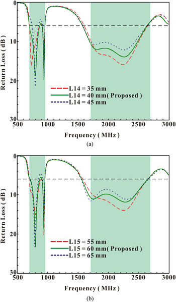
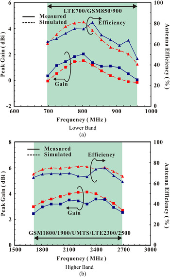
To achieve the desired impedance match, in this study, the rectangular notch plays an important role for the system ground plane. Figure 5 summarizes the results of the simulated RL for various dimensions of the rectangular notch. This figure reveals less effect on the impedance matching of the resonant modes at the lower and higher operating bands. It indicates that the proposed MA antenna can be more feasible for various battery dimensions of the practical mobile phones. For a complete study of the far-field performance of the proposed compact antenna inside an anechoic chamber, an Agilent N5230A vector network analyzer and a computer workstation running three-dimensional (3D) NSI 800F far-field measurement software were used according to generally applied methodologies for measuring antenna gain, directivity and efficiency as described in IEEE Standard Test Procedures for Antennas: ANSI/IEEE-STD149-1979 [17]. The proposed compact MA is arranged on the test platform to receive power radiated from the transmitted double-ridged horn antenna with a 1–18 GHz operating frequency. The measured peak gain is then obtained using the gain transfer method by utilizing a standard gain horn antenna as a reference. The calculation for radiation efficiency was the ratio of radiated power to total power supplied to the radiator at a given frequency [17]. Figure 6 presents the measured antenna gain and efficiency (mismatching loss included, [Reference Huang and Boyle18]) for the proposed compact multiband antenna. The simulation results are summarized in this figure for comparison with the measured ones. For frequencies over the lower band, the measured antenna gain and efficiency are approximately 0.1 ~ 2 dBi and 46– 80%, respectively. Meanwhile, the gain for the higher band ranges from ~2.4 to 3.6 dBi, while the antenna efficiency is ~61 – 75%.
Simulated RL against frequency for the proposed MA with C-shaped ground system of various dimensions. (a) RL versus L14. (b) RL versus L15.

Measured and simulated antenna gain and efficiency for the proposed small-size printed monopole antenna. (a) Lower band. (b) Higher band.

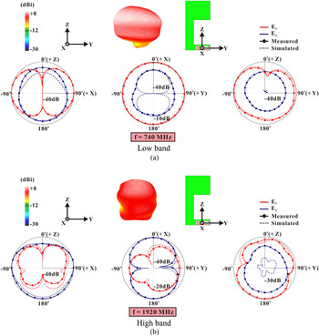
Figure 7 illustrates the measured 3D total-power radiation with three radiation patterns seen from the top, front, and side directions at typical frequencies of 740 and 1920 MHz bands. On one hand, at 740 MHz in the antenna's lower band, it is observed that the radiation patterns are omnidirectional in the azimuthal plane (x–y plane), which is close to half-wavelength dipole-like patterns. On the other hand, at 1920 MHz in the higher band, since the operating wavelength is comparable to the length of the system ground plane, more variations and dips can be observed in the radiation patterns, especially in the azimuthal plane due to the surface current nulls usually excited in the system ground plane.
Measured 3D total-power radiation patterns for the proposed planar multi-band monopole antenna.

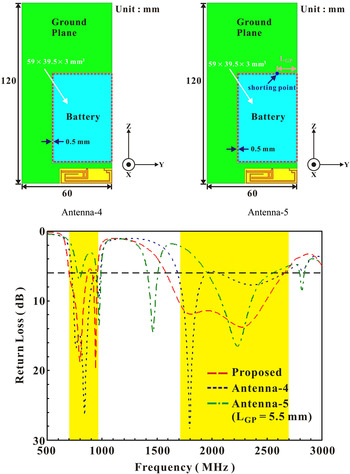
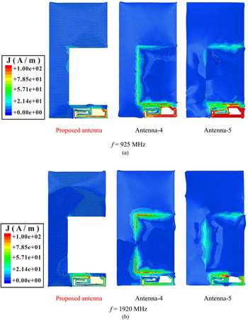
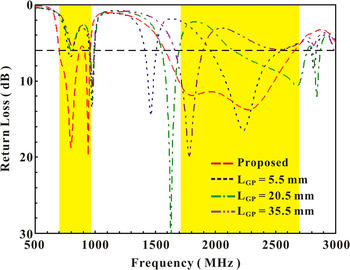
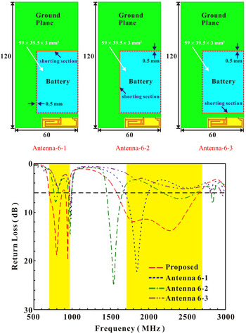
Effects of the battery embedded into the shaped ground plane are also analyzed. The battery is modeled as a metal box with the dimension of 59 × 39.5 × 3 mm3 enclosed by a 0.2 mm thick plastic casing (ε r = 3.2), as shown in Fig. 1 in [Reference Lu and Guo15]. The gap between the battery and the shaped ground plane is 0.5 mm. The metal box is also short-circuited at the position of point GP to the ground plane of shaped circuit board with the distance of L GP . Figure 8 shows the simulated RL for the battery isolated with the shaped circuit board (Antenna 4), the battery shorted with the shaped circuit board at the certain position (Antenna 5 with L GP = 5.5 mm) and the proposed design. Results indicate that for Antenna 5, due to the great variation of the excited surface current on the shaped ground board when there is the connection, the impedance matching is degraded to be far from covering the low- and high-band for LTE/WWAN bands. However, for Antenna 4 with the isolation between the battery and the shaped circuit board, the obtained operating bandwidths in the antenna's lower and upper bands are similar to those of the proposed antenna. This above behavior may be explained from the excited surface current distributions shown in Fig. 9, in which it is observed that, for the proposed antenna and Antenna 4, similar surface currents on the portion adjacent to the notch in the longitudinal direction are found. On the other hand, for the Antenna 5, the surface current distributions of the low- and high-band are significantly different from those for the proposed antenna. Then, the study of various shorted positions has also been investigated and illustrate in Fig. 10. We can find that the excited surface currents on the shaped ground board are greatly affected with various shorted positions. Therefore, the impedance matching cannot meet the bandwidth requirement of the low- and high-band for LTE/WWAN applications. It is also noted that, for the high-band, the resonant mode close to 1800 MHz band is decreased with the distance (L GP ) increased (i.e. the case with the shorted position more close to the vertical edge of the shaped ground plane). Moreover, Fig. 11 illustrates the RL against the operating frequency for Antenna 6 with various sections shorted with the shaped ground board. Similarly, the impedance matching for dual-band operation of LTE/WWAN bands becomes worse for each case of Antenna 6 with shorted section. It is also noted that as the shorted section closer to the MA (i.e. the case of Antenna 6–3), the obtained results become worse due to the surface current distribution significantly affected.
Simulated RL for the battery isolated (Antenna 4) and shorted (Antenna 5) with the shaped circuit board, and the proposed design.

Simulated surface current distributions on the ground plane of shaped circuit board for various antenna designs. (a) f = 925 MHz. (b) f = 1920 MHz.

Simulated RL for the battery shorted at the various positions for Antenna 5.

Simulated RL for the battery shorted with the various sections for Antenna 6.

IV. CONCLUSION
This work proposes a modified F-shaped MA to excite with dual parasitic monopole strips shorted in a C-shaped system ground and provides eight-band operation for an LTE/WWAN mobile phone. The impedance bandwidth across LTE and WWAN bands can approach ~263 and 1093 MHz, respectively. The measured peak gains and antenna efficiencies are approximately 2/3.6 dBi and 80/75% for the LTE/WWAN bands, respectively. The overall antenna size of the proposed printed MA is only 35 × 10 × 0.8 mm3.
Simulated and measured operating bandwidths of the proposed LTE/WWAN monopole antenna.

ACKNOWLEDGEMENTS
It is a particular pleasure to acknowledge the grant and support of the Ministry of Science and Technology (MOST), Taiwan, Republic of China. (Ref no. NSC101-2221-E-022-011-MY2 and MOST103-2221-E-022-003-MY2).
 Jui-Han Lu has received the Ph.D. degree in Electrical Engineering from National Sun Yat-sen University, Kaohsiung, Taiwan in 1997. In 2001, for his published SCI papers highly cited, he received the Institute for Scientific Information (ISI) Citation Classic Award for “Honoring Excellence in Taiwanese Research” from ISI and the National Science Council of Taiwan. In 2003, he became a Full Professor and was elected as Ten Outstanding Young Persons in Taiwan in 2005 for his contributions in antenna researches and academic-industry cooperation. From 2007 to 2010, Professor Lu served as Dean of the College of Ocean Engineering at National Kaohsiung Marine University. In 2013, with contributions in EM Theory teaching and Mobile Antenna researches, he received MOE (Ministry of Education) Outstanding Teaching and Research Award. Professor Lu presently serves as Chair of IEEE AP-S Tainan Chapter (2013–2014) and is the Awards Committee Chair of 2013 NST (National Symposium on Telecommunications in Taiwan), 2014 ISAP (International Symposium on Antennas and Propagation) and 2016 IEEE 5th Asia-Pacific Conference on Antennas and Propagation. He is a life member of IAET (Institute of Antenna Engineers of Taiwan) and a Senior Member of the IEEE.
 Ying-Sheng Fang has received the B.S. degree in Electronic Communication Engineering from National Kaohsiung Marine University, Kaohsiung, Taiwan in 2014. He is currently working toward the M.S. degree at National Kaohsiung University of Applied Sciences, Kaohsiung, Taiwan. His current research interests include antenna design and microwave circuit.