I. INTRODUCTION
Laser solid forming (LSF), as an advanced manufacturing technology, has made great progress and been applied in many high-tech fields in recent years.Reference Lu, Zhang, Tong, Yang, Li and Lu1–Reference Lupei3 However, this technology has its own shortcomings, such as solidification cracks and brittle precipitation phase with network distribution, which seriously limit its further development in engineering. Thus, the modifications of metallurgical defects such as cracks, pores, and brittle networks are considered to be very important to enhance the service lifetime and reliability of laser-processed components.Reference Lin, Lu, Wang, Xu and Xue4 Usually, toughening element addition,Reference Zhang, Zhang, Yan, Zhang, Wang, Song and Shi5 gradient heating, or preheating were applied to suppress the laser solidification crack; however, cracks cannot be thoroughly eliminated through these methods. Usually, the material failure originates from the surface of the LSF component,Reference DebRoy, Wei, Zuback, Mukherjee, Elmer, Milewski, Beese, Wilson-Heid, De and Zhang6 thus, repairing the surface crack is considered to be very important. It is well known that the ultrafine grain or nanograin endows the excellent mechanical properties from the Hall–Petch theory. Metals could be refined to nanograin by severe plastic deformation (SPD) on the surface with gradient variation from nano to micro.Reference Schiotz and Jacobsen7,Reference Liu, Zhang and Lu8 More importantly, SPD can enable the crack closure by strong material flow. Various surface SPD methods have been developed to crush the coarse grain into ultrafine grain, such as surface mechanical attrition treatment,Reference Samih, Beausir, Bolle and Grosdidier9 air blast shot peening,Reference Unal and Varol10 surface mechanical grinding treatment,Reference Li, Tao and Lu11 and surface sliding friction. Compared with other SPD processes, friction stir processing (FSP), which is based on the fundamental principles of friction stir welding, can readily be used for preparation of ultrafine grains or nanograins.Reference Samih, Beausir, Bolle and Grosdidier9,Reference Zhang, Zhang, Niu, Chen, Wang, Xiao, Chen, Yu, Yuan and Bai12 During the FSP process, a rotary tool is plunged into workpiece and yields friction heat, then plasticizes the material.Reference Chen, Fujii, Tsumura, Kitagawa, Nakata, Ikeuchi, Matsubayashi, Michishita, Fujiya and Katoh13,Reference Grewal, Arora, Singh and Agrawal14 Recently, FSP has been widely used in preparing ultrafine grain and even nanograin materials.Reference Qian, Li, Xiong, Zhang and Lin15,Reference Li, Yuan, Qiu, Zhou and Li16 Previous literature studies have shown that FSP can not only crush brittle network into nanoparticles but also close the microcrack. Li et al. investigate FSP on the microstructure and mechanical properties of the Co–Cr–Fe alloy.Reference Li, Yuan, Qiu, Zhou and Li16 They pointed out that FSP could make the grain refinement from tens of micrometers to tens of nanometers with the microhardness increased up from 490 to 819 Hv of the laser parent alloy. All these studies indicate that FSP can significantly eliminate the metallurgical defects and improve properties of materials. The solidification crack is also another common metallurgical defect of LSF, especially for the high crack-sensitive material, but the previous investigations on crack repairing by FSP are few. FSP has been proved to be an effective route for eliminating solidification crack and refining microstructure, such as high-entropy CrFeCoNiMoWC alloy,Reference Li, Wang, Yuan, Song and Shi17 Fe–Cr–Si alloy,Reference Xie, Li, Yuan, Chen, Zhang, Wang and Cao18 Co–Cr–W alloy,Reference Peng, Lia, Yuan, Wu and Yan19 Ni–Al–WC coating, and Ni– Cr–Fe alloy.Reference Xiong, Qiu, Li, Yuan, Wu and Liu20,Reference Xie, Li, Yuan, Chen, Zhou, Song and Shi21
In this paper, repairing the surface crack of the LSF-printed crack-sensitive Ni–16Cr–8Fe alloy by FSP was studied. Although this LSF-printed Ni–16Cr–8Fe alloy possesses outstanding oxidation and corrosion resistance, high-temperature mechanical properties have been applied in many practical engineering fields, such as turbine blade, vanes, valve trims, and this alloy is highly crack-sensitive. First, FSP is anticipated to eliminate the solidification crack, meanwhile transform the coarse microstructure into nanostructure. The nanograin formation, microstructural evolution, and mechanical and electrochemical properties were characterized, and the corresponding mechanisms were illuminated, so as to improve the mechanical performances and extend their applicable fields.
II. EXPERIMENTAL PROCEDURE
First, the chemical composition of a powder material of Ni-based alloy powder is as follows: C: 1.5%, Si: 1.5%, Fe: 8%, Cr: 16%, and Ni in balance. The Ni-based samples were deposited on a LSF system, which consists of 5 kW continuous wave CO2 laser, a four-axis numerical control working table, and a powder feeder with a coaxial nozzle. During laser processing, a continuous flow of argon gas was blown to the deposition zone to prevent the molten pool and thermomechanical effect zone from oxidation or contamination. The substrate was polished to reduce the surface reflectance with 400 mesh grit paper before cladding. The Ni–16Cr–8Fe alloy was prepared by laser cladding with Ar gas protection on the copper substrate with a dimension of 50 mm × 70 mm × 10 mm. The dilution ratio was below 10%. The laser cladding parameters were as follows: a laser power of 2.8 kW, a spot size of 3 mm, a scanning speed of 10 mm/s, and an overlapping ratio of 50%. A Ni–16Cr–8Fe block with the dimensions of length 100 mm, width 100 mm, and thickness 8 mm was built by LSF. After laser cladding experiments, the laser-clad Ni-based coating was processed by in situ FSP. The FSP tool made of the WC–Co alloy had a columnar shape with the diameter of 12 mm without a probe. The FSP parameters were as follows: rotation speed 600–1500 rpm and constant travel speed 10 mm/min. At last, the FSP-processed laser samples for metallographic examination were cut perpendicular to the friction surface and the samples for metallographic analysis were produced by standard methods. The microstructure was analyzed by SEM and the chemical composition was obtained by energy dispersive X-ray spectrometer (EDS) analysis. The microstructures of the laser cladding samples and laser-FSP samples were observed by transmission electron microscopy (TEM; JEOL-2100F, JEOL, Tokyo, Japan) operating at 200 kV, and high-resolution transmission electron microscopy (HRTEM) with the selected area electron diffraction (SAED) pattern. The microhardness was measured using a micro-Vickers hardness tester (Vickers, Foundrax, United Kingdom) with an applied load of 300 g for 10 s. The electrochemical corrosion behaviors of the Ni–16Cr–8Fe alloy before and after FSP were studied using potentiodynamic polarization. A conventional three-electrode cell assembly was used for electrochemical measurements, with a saturated calomel electrode as the reference electrode and a platinum foil as the auxiliary electrode. Potentiodynamic polarization scans were carried out with a scan rate of 1 mV per second. The potential range measured was from −0.15 to 0.15 V.
III. RESULTS AND DISCUSSION
A. Microstructure characterization of the LSF-printed Ni–16Cr–8Fe-based alloy
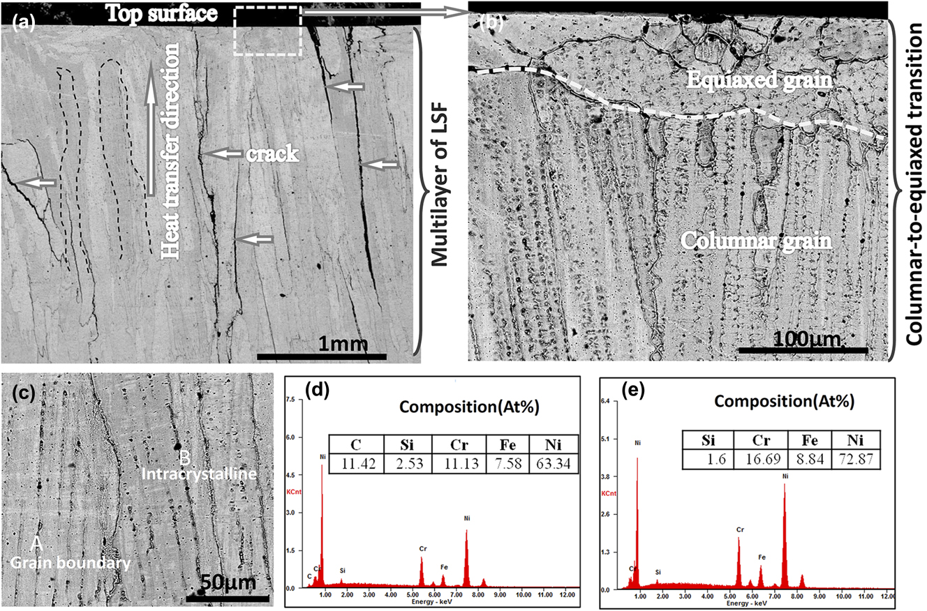
The typical SEM microstructures of the LSF-printed Ni–16Cr–8Fe-based alloy along the building direction are shown in Fig. 1. The columnar grains perpendicular to the top surface are visible, between which exist a great many of solidifying cracks and perpendicularly extend to the top surface of the printed part [Fig. 1(a)]. There are also micropores in the solidified structure, which not only decrease the density of the printed part but also worsen the anticorrosive capability and mechanical property of printed materials. According to Fig. 1(b), we can see the columnar-to-equiaxed transition (CET) from the inner to the top surface of the LSF-printed sample. In the interior of the LSF part, the grain grows into columnar shapes in the opposite heat transfer direction while it transfers into equiaxed grain at the end of solidification. The EDS analysis of the LSF produced part is shown in Fig. 1(c). It can be seen that C and Si elements are mainly distributed in the grain boundary (GB), suggesting the interdendritic segregation of C or Si. The brittle phase segregated in GB is very easy to incur the intercrystalline crack during the laser solidification process. Under the action of external force, the cracks are apt to propagate along the GB, resulting in GB fracture.
SEM images of the typical macrostructure (a) and microstructure (b) of LSF-processed Ni–16Cr–8Fe, showing solidifying crack (a) and CET (b). SEM morphology and EDS spectra of LSF Ni–16Cr–8Fe coating: (c) SEM morphology, and (d) and (e) spectrum of point A and B.

B. Solidification crack formation during LSF
The main features of LSF are fast heating, cooling, and nonequilibrium solidification, which lead to a complex heat and mass transfer. The rapid solidification of LSF easily results in a large thermal stress during LSF, and then causes cracks in the solidified layer. In addition, due to the gradient distribution of the temperature in the molten pool during the LSF process, the orientation of the eutectic grain is uncertain in the process of crystallization and compression and collision constantly. More importantly, with the growth of columnar crystals, the grain boundaries are in contact with each other. It can prevent the melted metal liquid from flowing down. All these will cause the crack generation.
During the solidification of the present crack-sensitive Ni–16Cr–8Fe alloy, the primary equilibrium phase solidifies first in the liquid of the different components, resulting in the solute enrichment of the liquid close to the solidifying interface. This phenomenon locally changes the equilibrium liquid temperature and then produces an unstable, undercooled condition. Thus, the decomposition of the solid–liquid interface leads to the growth of the crystal and dendrites along the liquid long channel. In the solidification region, with the decrease of temperature and liquid volume fraction, the volume solidification shrinks and thermal contraction of these channels will produce holes and hot cracks. These cracks may diffuse in the entire columnar grains and propagate through the intergranular regions.Reference Li, Wang, Yuan, Song, Chen, Zhou and Cao22–Reference Rappaz, Drezet and Gremaud25 In the present work, the FSP was successfully applied to eliminate the laser solidifying crack.
C. Microstructure evolution of the laser-clad Ni–16Cr–8Fe alloy by FSP
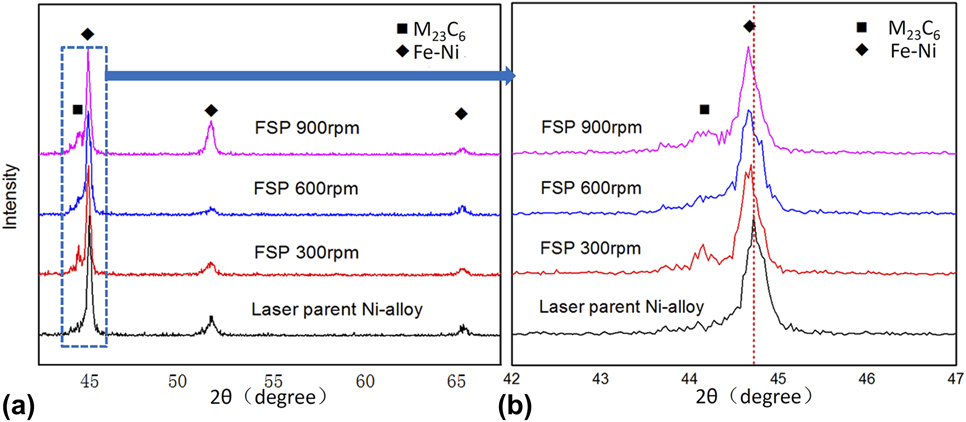
XRD was used to determine the phase composition of the LSF samples before and after FSP. As shown in Fig. 2, the Ni–16Cr–8Fe-based alloy is mainly composed of Ni–16Cr–8Fe solid solution with the austenite structure and M(Fe,Ni,Cr)23C6. Figure 2(a) illustrates that the phase compositions of the LSF alloy exhibit no significant difference before and after FSP, but the diffraction peaks shift to a lower angle. By the well-known Bragg’s formula 2d sin θ = λ, it can be inferred that the lattice parameters of the Fe–Ni phase increase after FSP, owing to the mixing of interstitial atom under strong deformation. In addition, with the increase of FSP rotary speed, the diffraction angle becomes higher, which is due to the much stronger strain under a higher FSP rotary speed.
(a) XRD pattern of the LSF Ni–16Cr–8Fe alloy layer before and after FSP with various rotary speeds and (b) the peak of Fe–Ni enlarged drawing.

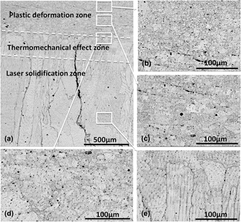
Figure 3 shows the typical microstructural evolution of the LSF-printed Ni–16Cr–8Fe alloy modified by FSP at a rotary speed of 900 rpm. Apparently, the solidification crack (running throughout the LSF part along the building direction) was closed under the strongly plastic flow at the surface, indicating that FSP is a feasible technique for repairing LSF cracks [Fig. 3(a)]. Besides, it can be seen that there are three typical zones in the cross section: plastic deformation zone, thermomechanical effect zone, and laser solidification zone. The plastic deformation zone characterized by submicrostructured grain at the top area with a thickness of about 320 μm was strongly stirred by using an FSP tool and subjected the high shear deformation, resulting in the transformation of coarse grains to ultrafine grains by breaking the coarse grains [Fig. 3(b)]. Beneath the plastic region is the thermomechanical effect zone, which grain size is between the grain size of the plastic zone and laser apparent zone under the influence of coupled stress and friction heat fields, but they are lower than the plastic zone; the thermomechanical effect zone is the transition zone between the ultrafine and original laser solidification microstructure [Fig. 3(d)]. The laser solidification zone below the thermomechanical effect region showed no significant microstructure change.
SEM images taken from the cross section of the Ni–16Cr–8Fe layer after FSP with a rotary speed of 600 rpm: (a) low magnification, (b) and (c) high magnifications showing the plastic deformation zone, (d) high magnification showing the interface of the plastic deformation and thermomechanical effect zone, and (e) high magnification showing the laser-solidified zone.

To further observe the plastic deformation zone, TEM was used to identify the detailed microstructure, as shown in Fig. 4. It can be seen that the laser-solidified grain was dramatically refined even broken into nanograins, owing to the effect of SPD and the resultant dislocation glide induced by FSP [Figs. 4(a) and 4(b)]. Meanwhile, a large number of subgrains and dislocations can be found in the TEM images. In addition, in the plastic deformation zone, the dynamic balance of strong strain and recovery causes dynamic recrystallization, which will also refine the microstructure with the mechanism of “strain-induced GB migration”.Reference Jafari, Jamshidian, Ziaei-Rad, Raabe and Roters26 The austenitic phase with the fcc crystal structure of the matrix was confirmed by the SAED image with a zone axis of [011] [Fig. 4(c)]. The CrC phase can be observed in the SAED image with a zone axis of [001] [Fig. 4(d)]. HRTEM was then conducted to observe the plastic zone, as presented in Fig. 5. Figures 5(a)–5(d) show the deformation twins. Some of the boundaries of deformation twin or matrix lamellae are fuzzy owing to the interactions between dislocations and twin boundaries (TBs) and the activation or propagation of dislocations in the twins.Reference Morisada, Fujii, Mizuno, Abe, Nagaoka and Fukusumi27 So it is suggested that the TB stems from the GB. This is due to the grain suffers heavy stress during the FSP process, which leads to stacking fault and deformation twinning,Reference Razmpoosh, Zarei-Hanzaki, Heshmati-Manesh, Fatemi-Varzaneh and Marandi28 which can be observed in Fig. 5(a). Twinning is another important microstructure deformation and grain refinement mechanism. Besides, ultrafine even near-amorphous can be observed in Fig. 5(d). The formation of amorphous was also observed in FSP of other alloys, during which the material experienced the severest plastic deformation.Reference Morisada, Fujii, Mizuno, Abe, Nagaoka and Fukusumi29 Therefore, twinning and dislocation are considered to be the dominant mechanism for the evolution of the microstructure. So it proves that dislocation slips, stacking faults, and twinning cause grain fractures and refinement.
(a) and (b) TEM bright-field images of the plastic zone showing the subgrain Ni–16Cr–8Fe-based alloy surface layer processed at an FSP rotary speed of 300 rpm; (c) and (d) corresponding SAED patterns of (a) and (b).

HRTEM showing the formations of (a) and (d) subgrain TEM bright-field images showing the deformation twins (b) and corresponding diffraction pattern (c) of the deformation plastic zone.

The rotary speed of the stirring head is the main factor determining the microstructural evolution. When a low rotary speed of 300 rpm was applied, a different microstructure is formed, as shown in Fig. 6. The thickness of the plastic deformation zone was decreased to 80 μm [Fig. 6(a)] compared with the plastic deformation zone of 320 μm at a higher rotary speed of 900 rpm [Fig. 3(a)]. In the deformation plastic zone, the continuous network is crushed into submicron structure, where the subparticles are evenly distributed [Fig. 6(b)]. It can be found that the WC–Co layer at the top of the deformation plastic zone appeared as what can be seen in Fig. 6(b), with a thickness of about 10 μm. During the FSP process, the Ni–16Cr–8Fe alloy sample reaches a very high temperature under remarkable friction heat. Concurrently, it makes the sample soften quickly. Under this circumstance, the FSP tool was worn, so the nanostructured WC–Co layer formed, which eventually stuck together with the deformation plastic zone and retained at the top surface.
SEM images taken from the cross section of the Ni–16Cr–8Fe layer after FSP with a low rotary speed of 300 rpm: (a) low magnification; (b) showing the plastic deformation zone; (c) high magnification of (b); (d) showing the submicron grain in the plastic deformation zone.

With the rotary speed further increased to 600 rpm, the thickness of the deformation plastic zone becomes much thicker with the thickness of about 200 μm, as shown in Fig. 7. Furthermore, the changing WC–Co layer thickness is consistent with the deformation plastic zone. It should be noted that the nanostructure consists of dispersive nanoparticles, which is similar to the results of FSP of other alloys.
SEM images taken from the cross section of the Ni–16Cr–8Fe layer after FSP with a rotary speed of 600 rpm: (a) low magnification, (b) high magnification of the deformation plastic zone, and (c) and (d) are the further magnification of (b).

When the rotary speed of FSP was increased to 1200 rpm, the deformation plastic zone was expanded to about 400 μm. From Fig. 8, it can be found that a large number of nanotwins appeared at the deformation zone due to the high rotary speed, in which a strong thermomechanical coupling and high shear deformation effect occurred in the plastically deformed zone.
SEM images taken from the cross section of the Ni–16Cr–8Fe layer after FSP with a rotary speed of 1200 rpm: (a) low magnification, and (b) and (c) are the high magnification of different deformation plastic zones.

D. Effect of FSP on properties of the LSF Ni-16Cr-8Fe alloy
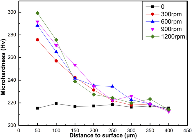
Figure 9 shows the microhardness profile along the cross section of the Ni-based alloy before and after FSP with different rotary speeds and different depths. It is obvious that the microhardness was markedly improved from 212 Hv of the parent material to 299 Hv at the top surface of the plastic region after FSP. Furthermore, a higher rotary speed, to some extent, can lead to a higher hardness. This is because higher rotational speed will result in much severer SPD, which then leads to a finer microstructure. The variations of hardness are inversely proportional to the grain size, which is consistent with the well-known Hall–Petch theory. Besides, the microhardness decreases with the depth from the deformation plastic zone to the original laser zone because the plastic deformation ratio becomes lower far from the surface. Li et al.Reference Li, Yuan and Qiu30 also reported that nanocrystallization occurred in the surface with gradient grain size ranging from tens of nanometers to tens of micrometers along the depth direction, which leads to a gradient mechanical property.
Microhardness in depth of the cross section of the Ni–16Cr–8Fe-based alloy prepared by LSF and subsequent FSP.

E. Strengthening mechanism
The LSF Ni–16Cr–8Fe-based alloy layer exhibited more prominent performance after FSP. There are three kinds of strengthening mechanisms involved in the process. The first is dislocation strengthening mechanism. During the FSP process, it can produce massive crystal defects, such as dislocation and stacking fault. When the nanostructured material is subjected to external loads, it can prevent the dislocation movement, thereby increases the strength. The second strengthening mechanism is fine grain strengthening.Reference Song, Wang, Yan, Zhang, Zhang, Cai, Wei and Shi31 According to the Hall–Petch formula, fine particles can induce strength increments and can be calculated as follows:
 $$\Delta {\sigma _{{\rm{Hall}} - {\rm{Petch}}}} = k{d^{ - {1 / 2}}}\quad ,$$
where k is the Hall–Petch slope and d is the grain size. According to Eq. (1), the strength of the Ni–16Cr–8Fe-based alloy increases with the decrease of grain size, which improves the strength of the Ni-based alloy due to the formation of nanocrystals on the surface after FSP. The last strengthening mechanism is Orowan strengthening (ΔτOR) and the contribution of the Orowan strengthening can be estimated by the following equationReference Liu, Zhang, Jiang, Ding, Sun, Sun and Ma32:
 $$\Delta {\tau _{{\rm{OR}}}} = {{\varphi {G_{\rm{m}}}b} \over d}{\left( {{{6V} \over \pi }} \right)^{1/3}}\quad ,$$
where G m is the shear modulus of the matrix and b is the Burgers vector. d and V are the volume friction and the size of the dispersion phase, respectively. φ is a constant around the order of 2. After FSP, the coarse network carbides were crushed into dispersed nanoparticles in the Ni solution matrix, resulting in very small d and large volume fraction. In a word, the combined contributions of dislocation strengthening, fine grain strengthening, and Orowan strengthening improved the mechanical properties of the LSF Ni-based alloy after FSP.
F. Electrochemical properties of Ni–16Cr–8Fe
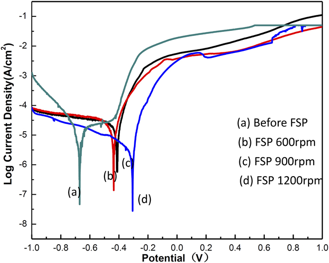
Figure 10 shows the potentiodynamic polarization curves of the Ni–16Cr–8Fe-based alloy before and after FSP. It can be seen that FSP has a significant influence on the corrosion resistance. Usually, the corrosion resistances were improved after FSP. The increase of FSP rotary speed also improves the corrosion resistance. In the laser-melted Ni–16Cr–8Fe-based alloy, there are two microstructures: austenite and continuous M(Fe,Ni,Cr)23C6 phase, which have different potentials about corrosion resistances. It is known that the continuous M23C6 phase at the GB promoted the corrosion. The continuous M23C6 is uniformly distributed after FSP. Meanwhile, the carbide phase was crushed into nanoparticles inside the austenite nanograins instead of on the boundaries. All these are helpful for the improvement of their electrochemical corrosion property.
Potentiodynamic polarization curves of the Ni–16Cr–8Fe-based alloy at different FSP rotary speeds.

IV. CONCLUSIONS
In this paper, a new LSF technology assisted by FSP is investigated to eliminate the solidified crack and refine the microstructure. In FSP, microstructure modification is induced and the mechanical performance is improved. Therefore, LSF assisted by the FSP technology for the preparation of laser materials has abroad application prospects. The main results can be summarized as follows.
(1) The microstructure of the LSF-printed Ni–16Cr–8Fe alloy is mainly composed of columnar and cell particle grains. There exists a great many of solidifying cracks between columnar grains; cracks are even extend from inner to the top surface of the printed part. The phase compositions of the LSF Ni-based alloy are Fe–Ni, M23C6. The brittle second phase tended to precipitate along GB, forming continuous network microstructures in the LSF alloy.
(2) FSP is found to be an effective route for eliminating the LSF crack at the surface and also transforming the network carbides into uniform nanoparticles dispersed in the base austenite. The austenitic grain is refined with the occurrence of large number of lamellar nanocrystal and nanotwins.
(3) With the rotary speed increased from 300–1200 rpm, the plastic deformation layer thickness increased from 80–400 μm. The hardness is increased by about 20–33%, which is much higher than that of the LSF Ni–16Cr–8Fe-based alloy. The main strengthening mechanisms are refinement strengthening, working hardening, and dislocation strengthening.
(4) The corrosion resistances of the Ni–16Cr–8Fe alloy were improved after FSP. This is mainly due to austenite and continuous M(Fe,Ni,Cr)23C6 phase have different potentials about corrosion resistance and the continuous M23C6 is uniformly distributed after FSP. All these are helpful for the improvement of their electrochemical corrosion property.
ACKNOWLEDGMENTS
The authors wish to acknowledge the financial support of National Natural Science Foundation of China (51505166, 51474245, and 51771233), National Key Research and Development Program “Additive Manufacturing and Laser Manufacturing” (2016YFB1100101), and Hunan Natural Science Foundation (2018JJ3659).