I. INTRODUCTION
Wetting of a solid surface has been the subject of research at the border separating physics and chemistry for many years. Wettability control of a solid against a liquid is widely investigated in industry because it can support various beneficial physical and chemical phenomena related to solids and liquids. Wettability is commonly compared by the contact angle (CA) (θ), which is given by Young's equation as
 $${\gamma _{{\rm{SG}}}} = {\gamma _{{\rm{SL}}}} + {\gamma _{{\rm{LG}}}}\cos \itheta \quad ,$$
where γSL, γSG, and γLG, respectively, represent the interfacial free energies per unit area of solid–liquid, solid–gas, and liquid–gas interfaces. This equation is valid for the wettability of a homogeneous smooth solid surface.
Hydrophobic coatings, representing an important technology for wettability control, are anticipated for use in various industrial applications such as anti-wetting, anti-snow (or ice)-adherence, anti-rusting, and reduced friction resistance by decreasing solid–liquid interaction. Generally, a hydrophobic surface is one on which water forms a round droplet (water CA >90°) that is removed easily.
The maximum CA on a flat surface that is attainable merely by lowering the surface energy is calculable as approximately 115°. Reference Nakajima1 Providing surface roughness to enhance hydrophobicity is necessary to obtain a greater CA. Reference Wenzel2,Reference Cassie and Baxter3 Surfaces, materials, and states in which water CAs are greater than 150° are generally designated as superhydrophobic. All superhydrophobic surfaces have been obtained by combining surface roughness with lowering surface energy. Reference Nakajima, Hashimoto and Watanabe4–Reference Blossey6 Excellent water shedding properties of superhydrophobic surfaces are obtainable by air intrusion in the hydrophobic solid–liquid interface, which decreases the practical contact area between a solid and liquid. Reference Miwa, Nakajima, Fujishima, Hashimoto and Watanabe7,Reference McHale, Shirtcliffe and Newton8 However, practical application of this surface remains limited because of insufficient mechanical strength and inadequate long-term outdoor durability. Reference Nguyen, Brunet, Coffinier and Boukherroub9,Reference Bocquet and Lauga10
Very recently, a new bulk composite material prepared by impregnating low-surface-energy liquid in hydrophobic porous solid with interconnected pore structure was proposed (hereinafter, the material is described as solid–liquid bulk composite (SLBC) in this text). Reference Wong, Kang, Tang, Smythe, Hatton, Grinthal and Aizenberg11 The pore structure of the material is used not as a field for chemical reactions but as one for retaining the liquid in the solid. The SLBC surface becomes either a mixture of a hydrophobic solid with a low surface energy liquid or only the liquid. That surface provides a low SA for water droplets: The critical angle at which a liquid droplet starts sliding down on an inclined surface by gradual tilting. The impregnated liquid does not flow out of the porous solid easily because of the capillary pressure. When the SLBC surface is damaged, the impregnated liquid spreads over the portion and prevents remarkable deterioration of surface hydrophobicity. Consequently, SLBC can overcome the shortcomings of superhydrophobic surface.
Preparation of SLBC requires satisfaction of the following several conditions for impregnated liquid: (a) stability in the porous solid, Reference Courbin, Denieul, Dressaire, Roper, Ajdari and Stone12 (b) wettability against porous solid surface, Reference Bauer and Federle13 and (c) no mixture against water droplets on the surface. Various phenomena such as droplet sliding, evaporation, condensation, and frost formation, and the effects of solid structure or impregnated liquid properties on the of SLBC performance have been studied extensively since 2011. Reference Lafuma and Quéré14–Reference Yao, Hu, Grinthal, Wong, Mahadevan and Aizenberg22 However, research on SLBC using porous ceramics that have better chemical or thermal stability than polymers remains limited. Moreover, the reports describing dynamic hydrophobicity such as sliding or moving velocity on SLBC are scarce compared with those describing static hydrophobicity, which is not a function of time as the SA is. Recently, reports have described that slipping and rolling modes exist for the sliding motion of a water droplet. Reference Gogte, Vorobieff, Truesdell, Mammoli, van Swol, Shah and Brinker23,Reference Hodges, Jensen and Rallison24 Nevertheless, no report to date describes the sliding motion of water droplets on an SLBC surface. Furthermore, control of liquid droplets on a solid surface has attracted much attention as an indispensable technology for various industrial items including MEMS or lab-on-a-chip, especially for hydrophobic coatings. To date, various investigations have been conducted to examine the motion of a liquid droplet on a solid surface using external fields such as a heat gradient, Reference Brzoska, Brochard and Rondelez25 gravity, electric fields, Reference Takeda, Nakajima, Hashimoto and Watanabe26 magnetic fields, Reference Hong, Gao and Jiang27 photo-illumination, Reference Ichimura, Oh and Nakagawa28 and blowing wind. Reference Hashimoto, Sakai, Yoshida, Suzuki, Kameshima and Nakajima29 However, water droplet control on an SLBC by an external electric field has not been reported in the literature.
Based on that background, we prepared alumina-based porous ceramics. Then a hydrophobic silane coupling agent was coated onto the porous alumina. Subsequently, SLBC was prepared by impregnating fluorinated oil in the porous alumina. Using the SLBC, we investigated the effects of the solid structure on the static and dynamic hydrophobicity, and of the external electric field on the motion of water droplets on the SLBC.
II. EXPERIMENTAL
A. Sample preparation
We prepared alumina-based porous ceramics according to the following process described by Tokudome et al. using phase separation. Reference Tokudome, Fujita and Nakanishi30 Aluminum chloride (43.2 g, AlCl3·6H2O; Aldrich) was dissolved in a mixture of water (40 g) and ethanol (43.5 g). Then, polyethylene oxide (0.8 g, (C2H4O) n ; Aldrich) was dissolved gradually in the solution. Subsequently, propylene oxide (31.1 g, C3H6O; Aldrich) was added. The liquid was stirred until a clear homogeneous solution was obtained. These operations were conducted under an ice-cooling condition. The obtained clear solution was sealed and aged at 40 °C for 24 h. During this aging, the solution changed to opaque gel, which was removed carefully from the reaction vessel. Then liquid in the gel was replaced from the water/ethanol mixture to acetone and methyl ethyl ketone by soaking the gel in the solvent for a few days. Subsequently, the gel was dried gradually at room temperature for 14 days. Finally, it was dried in vacuum for 1 day. The dried porous gel was fired at 550, 750, 1000, and 1100 °C for 5 h in ambient air. Thereby, alumina-based porous ceramics were obtained.
We conducted hot-water treatment on the alumina-based porous ceramic fired at 750 °C with the following work by Tadanaga et al. Reference Tadanaga, Katata and Minami31 to provide fine roughness on the surface. The alumina-based porous ceramic was immersed in pure water under vacuum for 3 h to impregnate water completely in the pores. Then, hot-water treatment was conducted by immersing the sample in boiling water for 0.5, 1, 2, 4, and 6 h. After drying, the sample was fired again in ambient air at 700 °C for 0.5 h.
The obtained alumina-based porous ceramics were cut and washed in ethanol for 15 min by sonication. After drying, we coated hydrophobic silane coupling agent (1H, 1H, 2H, 2H-perfluorodecyltrimethoxysilane (FAS17, CF3(CF2)7(CH2)2Si(OCH3)3, TSL8233; GE Toshiba Silicones, Tokyo, Japan) onto the alumina-based porous ceramics. The coating was formed by heating the sample with 20 μL of FAS17 in a Petri dish with flowing N2 at 155 °C for 3 h. Then, fluorinated oil (Fluorinert FC-43, C12F27N (MC); 3M, MN) was impregnated in the hydrophobic porous alumina for 3 h under vacuum. Subsequently, the SLBC samples were obtained.
B. Characterization and wettability evaluation
The crystalline phase of the samples was evaluated using x-ray diffraction (XRD; XRD-6100; Shimadzu Corp., Kyoto, Japan). The morphology of alumina-based porous ceramics was observed using a field-emission scanning electron microscope (SEM; S-800; Hitachi Ltd., Japan). The specific surface area and pore size distribution were evaluated using BET method and BJH plot with N2 (BELSORP-mini; Bel Japan Inc., Japan). The sessile drop method, using a commercial CA meter (Dropmaster DM-500; Kyowa Interface Science Co. Ltd., Japan) and 3.0-μL water droplet, was used to measure the CAs. The sliding angle (SA) of a 15-μL water droplet on the coatings was measured using an automatic measurement system (SA-20; Kyowa Interface Science Co. Ltd.). The surface energy of fluorinated oil was measured using the pendant drop method (DSA20; Krüss, Germany). The internal fluidity during sliding of water droplets on these coatings was evaluated using our particle image velocimetry (PIV) system.Reference Sakai, Hashimoto, Yoshida, Suzuki, Kameshima and Nakajima 32 Using this technique, the internal fluidity and velocity distribution during sliding are directly obtainable. Figure S1 (in Supporting Information) presents this system arrangement. For PIV analyses, the water droplet contained 0.06 mass% fluorescent particles (mainly polystyrene, 3 μm diameter, 1.05 cm3/g density, 542 nm excitation wave length, 612 nm R0300 emission wave length; Duke Scientific Corp., CA). The respective surface energy and viscosity of the test fluid were 70 mJ/m2 and 1.05 mPa s, respectively. A 20-μL droplet of the test fluid was prepared using a microsyringe on the sample surface inclined at 35°. A sheet-shaped laser beam (Ar ion type, 1000 mW intensity, 488 and 514 nm wave lengths, approximately 200 μm width; Seika Corp., Tokyo, Japan) was emitted vertically to the droplet and was set to the center of the droplet during sliding. After gently moving the microsyringe tip upward, dynamic images of the excited particles were taken using a high-speed camera (1024PCI; Photron Ltd., Tokyo, Japan) arranged at 35° (slope inclination). The droplet velocity was calculated from the change of relative position against the external scale on the center of gravity for a moving droplet obtained from Image J software because of the existence of wetting ridge (to be described later). The internal velocity vectors were evaluated using PIV software (DIP-Macro-KAST; Ditect Co. Ltd., Tokyo, Japan, KAST, Kanagawa, Japan). Detailed methods for the analysis of rolling and slipping elements in the obtained sliding velocity are described in the literature.Reference Sakai, Hashimoto, Yoshida, Suzuki, Kameshima and Nakajima 32 , Reference Suzuki, Nakajima, Sakai, Sakurada, Yoshida, Hashimoto, Kameshima and Okada 33
C. Droplet control by external electric field
We coated FAS17 onto the alumina-based porous ceramic fired at 750 °C for 5 h in air and treated in hot water for 4 h. The sample was cut. Then two electrodes were prepared on the side of the ceramic using Ag paste and Cu tape (15 mm electrode distance). The sample was adhered onto a glass plate and the fluorinated oil was impregnated in the sample under vacuum. The obtained SLBC was connected to a power supply. A 5 μL water droplet was placed at the middle position between electrodes. A side view of the droplet motion on the SLBC during application of voltage (−1500 to +3000 V) was recorded using a high-speed camera system (1024PCI; Photon Ltd., Japan). Figure S2 (in Supporting Information) portrays a schematic illustration and a photograph of the sample assembly for this experiment. The stability of the fluorinated oil under this experimental condition was confirmed in the preliminary experiment.
III. RESULTS AND DISCUSSION
A. Sample preparation and static hydrophobicity
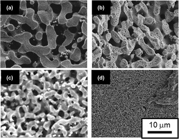
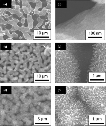
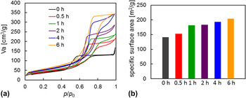
Figure 1 portrays XRD patterns of alumina-based porous ceramics fired at 550, 750, 1000, and 1100 °C for 5 h in ambient air. The main phase of the ceramic was amorphous when firing was conducted at 550 °C, but it changed to γ-alumina (750 °C), a mixture of γ-alumina and α-alumina (1000 °C), and α-alumina (1100 °C) with increasing temperature. Figure 2 presents SEM micrographs of porous ceramics fired at different temperatures. Spinodal three-dimensional frameworks were observed in the microstructure before firing. Then the frame part became porous by firing at 750 °C. Densification and the resultant pore size decrease progressed with increasing firing temperature. They became remarkable when fired at 1100 °C. Figure 3 presents SEM micrographs of porous ceramics fired at 750 °C and subsequent hot-water treatment for each time. The ceramic surface was covered with numerous scale-like projections. Tadanaga et al. reported that boehmite (AlOOH) crystallizes on the surface of transition alumina because of the hot-water treatment. Reference Tadanaga, Katata and Minami31 The projection morphology resembles that of boehmite. Reference Misra34 The phase was confirmed using XRD. Boehmite was converted to γ-alumina again by post-firing at 700 °C for 0.5 h. Figure 4 portrays changes of the adsorption–desorption isotherm and the specific surface area of alumina-based porous ceramics by hot-water treatment. (All samples were fired at 700 °C before this measurement.) Because of the precipitation of boehmite, the pore structure was altered. The specific surface area was increased. For this study, we used alumina-based porous ceramics fired at 750 °C for 5 h. The ceramics were treated in hot water for 4 h to prepare SLBC. Hereinafter, the samples are respectfully designated in this study as the alumina-based porous ceramics fired at 750 °C (neither hot-water treatment nor oil impregnation), the SLBC from the alumina-based porous ceramics fired at 750 °C (no hot-water treatment before oil impregnation), and the SLBC from the alumina-based porous ceramics fired at 750 °C and subsequent hot-water treatment for 4 h: A-0, A-f, and R-f.
XRD patterns of samples before firing and those fired at 550, 750, 1000, and 1100 °C.

SEM micrographs of porous alumina (a) before heating, and after firing at (b) 750 °C, (c) 1000 °C, and (d) 1100 °C.

SEM micrographs of porous alumina: (a) and (b), before hot-water treatment; (c) and (d), after hot-water treatment for 1 h; and (e) and (f), after hot-water treatment for 4 h.

Changes of (a) adsorption–desorption isotherm and (b) specific surface area of porous alumina by hot-water treatment. All samples were fired at 700 °C before this measurement.

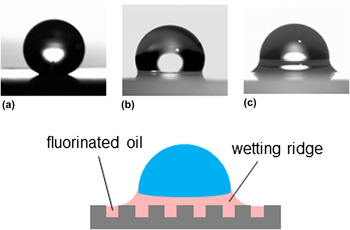
Figure 5 presents photographs of water droplets on A-0, A-f, and R-f samples. The water droplet on the homogeneous smooth solid surface becomes stable, with deformation only by its own morphology under an interfacial energy balance among solid, liquid, and air. The water droplet on SLBC becomes stable not only with deformation of its own morphology, but also with formation of a wetting ridge at its bottom. Because of the wetting ridge formation, which is a unique characteristic of SLBC, precise measurement of CA was not feasible. The surface energy for the fluorinated oil used for this study was 15.6 mJ/m2. The value was much less than that of water (72.8 mJ/m2). Reference Nakajima1 For that reason, the oil has a trend to wet the water droplet surface. The wetting ridge height depends on various factors such as Laplace pressures at each phase boundary and capillary pressure from alumina-based porous ceramics. Detailed analysis of the wetting ridge height will be conducted in future studies.
Morphology of water droplets on (a) the alumina-based porous ceramics fired at 750 °C (A-0), (b) the alumina-based porous ceramics fired at 750 °C and impregnated with fluorinated oil (A-f), and (c) the alumina-based porous ceramics fired at 750 °C, treated in hot-water treatment for 4 h, and impregnated with fluorinated oil (R-f).

The order of the apparent CA from the droplet shape was A-0 > A-f > R-f. However, the SAs for the water droplets on these samples were 21.2° (average from three measurements) ± 2.6° (standard deviation), 10.3° ± 3.2°, and 0.7° ± 0.5°, respectively, for A-0, A-f, and R-f. The spreading coefficient (S OS(W)) at the interface between SLBC and water is described as the following equation. Reference Smith, Dhiman, Anand, Reza-Garduno, Cohen, McKinleya and Varanasi20
 $${S_{{\rm{OS(W)}}}} = {\gamma _{{\rm{SW}}}} - {\gamma _{{\rm{OS}}}} - {\gamma _{{\rm{OW}}}}\quad ,$$
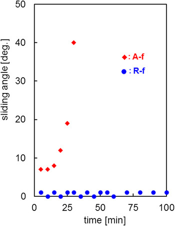
Therein, γSW, γOS, and γOW represent the interfacial free energies per unit area of solid–water, oil–solid, and oil–water interfaces, respectively. When S OS(W) > 0, oil spreads completely over the solid (no interface between solid and water), but when S OS(W) < 0, some part of the solid contacts with water. The practical γOW value measured using the pendant drop method in water was 54 mJ/m2. We measured the CA of water and fluorinated oil onto smooth FAS17 coating. The preparation of homogeneous smooth FAS17 coating on γ-alumina was not feasible. Therefore, we prepared such a coating on a Si substrate following the method used in our previous study. Reference Furuta, Sakai, Isobe and Nakajima35 Then, γSW (42.7 mJ/m2) and γOS (≅0 mJ/m2) were calculated using Young's equation (CA (θ) = 112.4 ± 0.3° (water) and 16.9 ± 0.7° (oil)) and the surface energy value of FAS17 coating (15 mJ/m2 (Ref. Reference Nakajima, Hoshino, Song, Kameshima and Okada36)). The calculated value of S OS(W) for this system was −11.3 mJ/m2. Based on this calculation, it is expected that some part of the solid contacted with water. Because of fine roughness provided by hot-water treatment, the practical solid–water contact area ratio for the R-f sample is smaller than that for A-f. This difference engenders the SA difference between A-f and R-f. It was inferred that the SA difference between A-0 and A-f is the decrease of pinning possibility Reference Furuta, Sakai, Isobe, Matsushita and Nakajima37–Reference Iliev and Pesheva39 for the motion of water droplets at the solid surface by oil coverage. One plausible pinning point in the surface of this SLBC is partial heterogeneity of FAS17 coating onto the γ-alumina surface. Reference Suzuki, Nakajima, Sakai, Sakurada, Yoshida, Hashimoto, Kameshima and Okada33 Figure 6 portrays the time dependence of the SA for A-f and R-f. A weak point for SLBC is the deterioration of properties attributable to the evaporation of impregnated liquid. The SA of A-f is greater than that of R-f. It increased after 20 min, whereas R-f sustained small SAs for 100 min. In addition to the surface thick oil layer, the surface becomes superhydrophobic with excellent water shedding property Reference Miwa, Nakajima, Fujishima, Hashimoto and Watanabe7 even if the oil evaporates completely (actually, the SA of water droplets before oil impregnation for R-f was less than 1°). Therefore, the SA value of R-f was not deteriorated, but was instead stable for a long period.
Time dependence of SAs for the alumina-based porous ceramics fired at 750 °C and impregnated with fluorinated oil (A-f), and the alumina-based porous ceramics fired at 750 °C, treated in hot-water treatment for 4 h, and impregnated with fluorinated oil (R-f).

B. Dynamic hydrophobicity and effect of external electric field
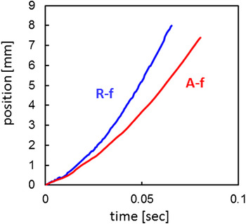
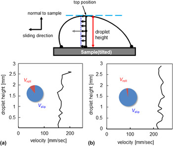
Figure 7 portrays a typical relation between time and sliding distance of water droplets on A-f and R-f obtained from PIV. Sliding acceleration for the droplets on A-f and R-f was calculated, respectively, as 1.36 m/s2 and 2.55 m/s2. These are 24% and 45% for the gravitational acceleration along the surface (g × sin35°). A certain amount of energy was dissipated in the droplet during sliding, and plausible candidates for the energy dissipation are pinning on the surface and viscous flow in the droplet. Reference Furuta, Sakai, Isobe, Matsushita and Nakajima37,Reference Nakajima, Miyamoto, Sakai, Isobe and Matsushita40 However, after 0.05 s, sliding distances were almost linear with time. This result suggests that the sliding velocity saturated gradually and approached a terminal value. Figure 8 portrays the sliding velocity from the bottom to the top position of a water droplet sliding on A-f and R-f at the distance of 6.1 mm. The rolling and sliding ratio in the figure were calculated using a method described in a previous report. Reference Suzuki, Nakajima, Sakai, Sakurada, Yoshida, Hashimoto, Kameshima and Okada33 (Practical internal velocity distribution images of a water droplet sliding on the SLBC surfaces are shown in Fig. S3 in Supporting Information.) For normal hydrophobic coatings such as FAS17, the bottom velocity is clearly smaller than the top velocity in the droplet during sliding. Reference Suzuki, Nakajima, Sakai, Sakurada, Yoshida, Hashimoto, Kameshima and Okada33,Reference Furuta, Sakai, Isobe and Nakajima35 However, such a velocity difference was not remarkable on the droplet sliding on the SLBC. The contribution of “rolling” on sliding behavior was regarded as small. Therefore, the main element became “slipping”. A plausible explanation of this result is the existence of a wetting ridge that resists the rolling motion of a water droplet on SLBC by covering the bottom part of the water droplet. However, the practical slipping interface for the droplet on SLBC is uncertain. The wetting ridge seemed to move with the droplet sliding on SLBC. Therefore, the viscosity of the impregnated oil might play an important role on the overall sliding behavior of the water droplet.
Relation between the time and sliding distance of water droplets on the alumina-based porous ceramics fired at 750 °C and impregnated with fluorinated oil (A-f), and the alumina-based porous ceramics fired at 750 °C, treated in hot-water treatment for 4 h, and impregnated with fluorinated oil (R-f).

Sliding velocity from the bottom to top position of a water droplet sliding on (a) the alumina-based porous ceramics fired at 750 °C and impregnated with fluorinated oil (A-f) and (b) the alumina-based porous ceramics fired at 750 °C, treated in hot-water treatment for 4 h, and impregnated with fluorinated oil (R-f). The rolling and sliding ratio in the figure were calculated in accordance with a method used in a previous study. Reference Suzuki, Nakajima, Sakai, Sakurada, Yoshida, Hashimoto, Kameshima and Okada33

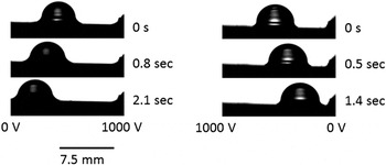
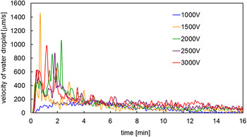
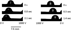
R-f provides better dynamic hydrophobicity. Therefore, we tried to control water droplets on the sample under an external electric field. Sequential photographs of the droplet motion under an electric field are presented in Fig. 9. The droplet always moved to the low voltage electrode side. Its height was also decreased slightly during its motion (Fig. S4 in Supporting Information). Figure 10 portrays the time dependence of droplet velocity by changing the electric field. This measurement was conducted by changing the voltage of one electrode while setting another electrode to 0 V. In the early stage (0–5 s) of voltage application, the velocity was large. Several spike-like rapid velocity changes were observed. However, after 5 s, the velocity became gradually constant. Its final value order after 12 s depends on the voltage. The average velocity values during 12–16 s were 105.3 (3000 V), 80.4 (2500 V), 60.3 (2000 V), and 39.6 (1500 V) μm/s. When the voltage was 1000 V, the droplet stopped at 12 s, probably because of pinning on the SLBC surface.
Sequential photographs of droplet motion on the SLBC (R-f) under an electric field.

Time dependence of droplet velocity on the SLBC (R-f) by changing the electric field. This measurement was conducted by changing the voltage of one electrode while setting another electrode to 0 V.

The force from the external electric field on a water droplet can be described as Reference Takeda, Nakajima, Hashimoto and Watanabe26
 $$F = {\rho _{\rm{t}}}E + {1 \over 2}\nabla \left( {{E^2}{{{\rm{d}}\varepsilon } \over {{\rm{d}}{\rho _{\rm{m}}}}}{\rho _{\rm{m}}}} \right)\quad ,$$
where E, ρt, ε, and ρm denote the electric field, true electric charge, dielectric constant of water, and true density, respectively. The first term on the right-hand side is the Coulomb force. The second term is the dielectrophoretic force. The dielectrophoretic force is important when the electric field is unequal for water droplets. Reference Sakai, Kono, Nakajima, Sakai, Abe and Fujishima41 It is commonly remarkable at the instant of applying voltage. However, the initial position of the water droplet was at the middle position between electrodes on the SLBC. The spike-like rapid velocity changes in the early stage (0–5 s), and does not always appear at the instant of applying voltage. Therefore, it is inferred that the contribution of this force in this stage of applying voltage is small. As described earlier, some direct contact exists between the solid and water in R-f. Several rapid velocity changes observed at this time are attributable to the release of the droplet from several pinning points in the SLBC. The continuous motion of the water droplet, even after 12 s, and the voltage dependence of velocity suggest the contribution of the Coulomb force. Fluorine-based polymers are the most negative in the triboelectric series. Reference Diaz and Felix-Navarro42 Therefore, fluorinated oil has a trend to be negative by adsorbing negative species such as OH−. Reference Yatsuzaka, Mizuno and Asano43 It is expected that the water droplet becomes positive by its contact with fluorinated oil, and that the Coulomb force was induced under an electric field. Because the direct measurement of charge amounts on the water droplet is not easy, we tried to estimate the value from the following indirect measurements.
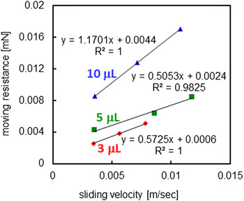
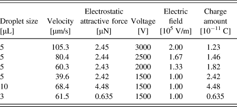
As described earlier, the water droplet that slid down on the SLBC gradually approaches the constant velocity motion. Under constant velocity motion, it can be assumed that the gravitational force along the slope is equal to the resistant force for sliding. Figure 11 shows the relation between the terminal sliding velocity and the resistant force for the 3, 5, and 10 μL water droplets with respective SLBC tilt angles of 5°, 7.5°, and 10°. These measurements were conducted at the sliding time of 1 s (5° and 7.5°) and 2 s (10°). Results show that the droplet sliding behavior can be inferred as constant velocity motion at these measurement times (Fig. S5 in Supporting Information). As might be readily apparent, the resistant force was linearly related to the terminal velocity (like a moving particle in the liquid). These force–velocity relations are valid only in a limited velocity region because y-intercepts of these lines are not equal to 0. However, the Coulomb force and charge amount are estimable from Fig. 11 and the droplet velocity under an electric field while assuming validity of these relations and constant electric fields (voltage/0.015 (V/m)). The calculation results are presented in Table I. This calculation was conducted not only for a 5 μL water droplet but also for 3 and 10 μL water droplets under 1500 V. According to results obtained by Yatsuzaka et al. using a Faraday cage, Reference Yatsuzaka, Mizuno and Asano43 the charge amount of a 5 μL water droplet sliding on the fluorine-based polymer (PTFE) is calculable as 1–3 × 10⁻¹¹ C. The order of this value is the same as that of the values presented in Table I. Although the Coulomb force functions according to the motion of water droplets on the SLBC surface, the contribution of the dielectrophoretic force cannot be ruled out because a slight droplet height decrease might be induced by this force after moving from the middle position between electrodes on the SLBC. Further systematic investigations by changing the droplet size and properties such as viscosity and polarity must be conducted to support detailed analysis of the contribution for these two forces to the overall droplet motion under an electric field. These are the issues to be addressed in future works.
Relation between the sliding velocity of water droplets and moving resistance on the SLBC (R-f).

Droplet size, moving velocity, electrostatic attractive force, applied voltage, applied electric field, and calculated charge amount of water droplets moving on the SLBC (R-f) under an electric field.

IV. CONCLUSION
Alumina-based porous ceramics with three-dimensional frameworks were prepared using phase separation. Scale-like fine projections were provided on the framework by hot-water treatment. After coating hydrophobic silane onto the ceramics and subsequent impregnation of fluorinated oil, porous alumina/fluorinated oil bulk composites were prepared. These bulk composites exhibited a small SA for the water droplet. Actually, the angle was found to depend on the porous ceramic microstructure. The composites with fine roughness retained a small SA for a long time period. Detailed interface energy analysis suggested partial contact between the porous ceramics with water. The water droplet on the composite surface slid down, approaching constant velocity motion with a small contribution of rolling, suggesting resistance by the wetting ridge. The water droplet on the composite surface moved to the low voltage electrode side under an electric field. The contribution of the Coulombic force to this behavior was confirmed.
Supplementary Material
To view supplementary material for this article, please visit http://dx.doi.org/jmr.2014.168.
ACKNOWLEDGMENTS
The authors are grateful to the staff of the Center of Advanced Materials Analysis (CAMA) at Tokyo Institute of Technology for SEM observations. This work was supported in part by a Grant-in-Aid for Scientific Research from the Ministry of Education, Culture, Sports, Science, and Technology of Japan.