Introduction
Crack growth on a concrete or steel structure is a particularly important sign of fracture initiation of structural materials by stress or aging.[1] Detecting a fine crack or measuring the crack width during periodic inspections requires labor-intensive methods, such as visually checking and short-range hammering on a high-elevation work vehicle.[2] The most significant problem with these methods is the uncertainty of data, which is worker-dependent under specific environmental conditions. For example, quantitatively determining the crack width in dark construction sites, such as the inner surface of a tunnel, the inside of a box girder, and the rear face of a concrete slab is challenging. Another problem is the inspection period determined by the law. For example, inspection of infrastructure every 5 years is required by each local government in Japan. In other words, the costs for setting up scaffolding must be dealt with every 5 years. Accumulating maintenance expenses for old infrastructure can aggravate tight financial situations.[3] In this context, novel fracture detection technologies, which are straightforward and can be operated from a remote place without scaffolding, have been sought and would contribute to the safety inspection of a large number of social infrastructures all over the world.
Recently, there has been an increasing number of reports about mechanical sensor materials.[Reference James, Adams, Bolm, Braga, Collier, Friscic, Grepioni, Harris, Hyett, Jones, Krebs, Mack, Maini, Orpen, Parkin, Shearouse, Steed and Waddell4–Reference Capadona, Shanmuganathan, Tyler, Rowan and Weder8] For example, Weder and co-workers developed luminescent polymer materials that showed a decrease in the emission intensity or color changes in response to the addition of a small amount of luminophores.[Reference Sagara, Yamane, Mitani, Weder and Kato9] Moore and co-workers reported a pioneering result regarding the practical application of self-healing polymers that respond to mechanical or dynamic stimuli.[Reference Caruso, Davis, Shen, Odom, Sottos, White and Moore10] As demonstrated by this research, functional materials based on the mechanochemistry concept have significant possibilities in the field of infrastructure maintenance. However, there have been few examples of their practical application because functional materials are generally expensive, and it is difficult to produce them on a large scale.
It is known that some luminescent dyes and complexes show luminescence quenching in response to oxygen molecules.[Reference Wang and Wolfbeis11] Optical oxygen sensors using such dyes and complexes as sensor elements were practically employed.[Reference Liu and Sullivan12] Luminescence or phosphorescence emitted from complexes, such as platinum-, rare earth-, and ruthenium-complexes, was efficiently quenched by circumambient oxygen molecules due to the Dexter-type energy transfer. Accordingly, the complexes have been widely studied and applied in both scientific and industrial fields by dissolving them in polymer resins or paints,[Reference Amao13] by grafting them on a surface,[Reference Wang, Zhang, Zhou, Liu and Lei14] and by adsorbing them onto a target cell for the visualization of oxygen concentrations.[Reference Quaranta, Borisov and Klimant15] In particular, over the past decade, a simple spray-coating approach, by dispersing the complexes in a gas permeable polymer binder, has been used for the tunnel tests, in which the air pressure from aircrafts, rockets, and automobiles can be visualized in a fluid dynamics manner.[Reference MacLachian and Bell16–Reference Sakaue, Hayashi and Ishikawa18] The paint was also developed to successfully monitor the oxygen consumption in the air channel of fuel cells.[Reference Inukai, Miyatake, Takada, Watanabe, Hyakutake, Nishide, Nagumo, Watanabe, Aoki and Takano19–Reference Hyakutake, Ishigami, Kato, Inukai, Miyatake, Nishide and Watanabe21] The key is to practicalize the luminescent oxygen sensor for specific functions, which is used to set the target range of oxygen concentration, and to envisage the installation environment.
This paper describes the first application of luminescent oxygen sensor polymers to a paint designed for microcrack detection. The optical crack sensor paint was designed as a three-layered integrated structure. The highly sensitive oxygen sensor layer, composed of a luminescent porphyrin complex embedded in a gas-permeable polymer matrix, was sandwiched between gas barrier polymer layers. This enables the isolation of the sensor layer from oxygen molecules in the air. The optical crack sensor could be coated onto concretes. When a crack occurred on the structural material, the gas barrier layers were destroyed and oxygen molecules penetrated into the sensor layer, resulting in the quenching of luminescence around the crack under the irradiation of light. In short, the cracked area turned dark, while other areas possessed their original bright luminescence. This result implies that the sensor paint could permit the visualization of damaged areas (in this case, concrete cracks) by a conventional visual check, even if it was in the dark. The crack-sensing performance was independent of the examined structural material because the sensor was a thin-coated paint.
The oxygen concentration of the atmospheric region is too high for highly sensitive visualization of oxygen molecules. On the other hand, luminescent complexes with low sensitivity to oxygen, which emit strong luminescence, even under atmospheric conditions, have not been used as oxygen sensors because they do not significantly respond to the change in oxygen concentration. Since the purpose of this study is to detect or visualize microcracks by the naked eye or a common digital camera, oxygen sensors must possess strong luminescence, and the luminescence must be efficiently quenched by the crack formation. The author designed the device structure of the highly sensitive oxygen sensor layer, sandwiched between two oxygen barrier layers to achieve the above objectives. The developed device served as an optical crack sensor paint.
The detection mechanism of microcracks on a structure is as follows. The luminescent crack sensor painted on the surface of a structure emits strong luminescence under favorable conditions. On the other hand, when a crack is formed, the oxygen barrier layers are also destroyed simultaneously. Luminescence quenching is caused by the spread of oxygen molecules over the sample surfaces formed by the crack.
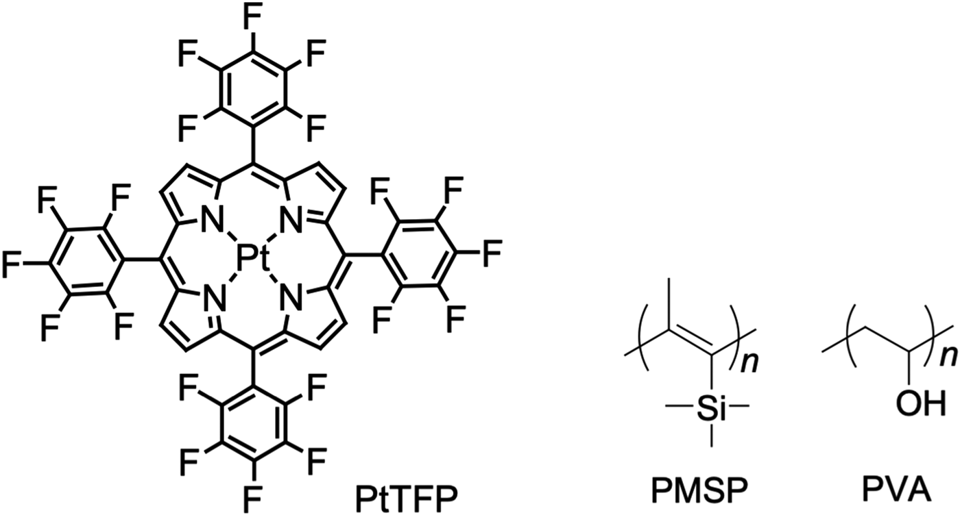
In this study, to demonstrate the crack visual sensor model, highly oxygen-sensitive platinum porphyrin (PtTFP) and highly oxygen-permeable poly(1-trimethylsilyl-1-propyne) (PMSP) were employed as the oxygen sensor dye and polymer matrix, respectively. Polyvinyl alcohol (PVA) was used for the oxygen barrier layers because of the high gas barrier ability and incompatibility of an aqueous solution. Fluorine-substituted platinum porphyrin derivatives are well-known luminescent dyes with durability, while PMSP maintains stable and high oxygen permeability in the glass state over a wide temperature range due to its unique porous structure.[Reference Nagai, Masuda, Nakagawa, Freeman and Pinnau22] PVA can be easily cross-linked to be insoluble in and resistance with water. These three components were combined to create the optical crack visualizing system for practical use (Chart 1).
Oxygen sensor complex (PtTFP), gas permeable polymer (PMSP), and gas barrier polymer (PVA).

Experimental
Materials
Oxygen sensor complex: 5, 10, 15, 20-tetrakis(2, 3, 4, 5, 6-pentafluorophenyl)platinumporphyrin (PtTFP) was purchased from Porphyrin Systems (www.porphyrin-systems.de), Lüebeck, Germany. Ti-based cross-linkers (TC-315) were obtained as 44 wt% water and 2-propanol solution from Matsumoto Fine Chemical Co., Ltd., Chiba, Japan, an epoxy-based undercoat set (EPONICS #10) was purchased from Dai Nippon Toryo Co., Ltd., Osaka, Japan, 1-trimethylsilyl-1-propyne and other chemicals were purchased from Sigma-Aldrich Co., MO, USA, and poly(1-trimethylsilyl-1-propyne) (PMSP) was synthesized as reported in the literature.[Reference Masuda, Isobe, Higashimura and Takada23] The molecular weight of poly(vinyl alcohol) (PVA) (Wako Pure Chemical Industries, Ltd.) was 2.2 × 10⁴ and the molecular weight of polymethylmethacrylate (PMMA) (Sigma-Aldrich Co.) was 1.2 × 10⁵.
Preparation of the oxygen sensor coatings and the absorption spectral measurements
An amount of 10 mg of PtTFP and 100 mg of PMSP were dissolved in 10 mL of toluene. The toluene solution was spray-coated with an air brush (Olympos Co.) on a quartz plate to obtain the oxygen sensor coating with a thickness of ~2 μm. Absorption spectra of the polymer coatings on the glass plate were measured with a JASCO V-550 UV-visible spectrometer.
Preparation of the crack sensor coatings and luminescence measurements
The oxygen sensor coating, composed of PtTFP and PMSP, was prepared by the above-mentioned spray-coating method onto a quartz plate. A 9.9 wt% PVA aqueous solution was drop-casted onto the coating and dried at room temperature for 1 day to evaporate the water. The resulting laminated crack sensor coating had a thickness of ~50 μm. The oxygen sensor layer was not dissolved in the PVA aqueous solution, which enabled the formation of a tough and smooth laminated coating. Steady-state luminescence spectra and excitation spectra of the coatings on the quartz plate were obtained by a Shimadzu RF-5300PC spectrofluorophotometer with a 150 W Xenon lamp as the excitation light source. Excitation and emission band passes were 3.0 nm. Excitation at 400 nm, attributed to the Soret-band of PtTFP, gave the maximum luminescence intensity at 650 nm. The quartz plate was set inside the optical cell connected with a nitrogen and air gas mixing apparatus. All the experiments were performed at 1 min intervals under a series of oxygen concentrations at room temperature (at 20–25 °C, in the range in which the luminescence was not influenced by temperature).
Oxygen and nitrogen permeation measurements for the coating
Self-standing PMSP and PMMA membranes with a thickness of ~100 μm were prepared by casting the toluene solution of the polymers. PVA membranes were prepared by casting an aqueous PVA (9.9 wt%) and Ti-based cross-linker (3.0 wt%) on a Teflon dish according to the literature,[Reference Duan, Kai, Saito, Yamazaki and Ikeda24] followed by drying at room temperature for 2 days to evaporate the water. Epoxy-type undercoat membranes were also prepared according to the practical use procedure. Oxygen permeation coefficients were measured using a low-vacuum permeation apparatus (GTR-1MDF) at 20 °C. The permeation coefficients were calculated from the slope of the steady-state straight line of the permeation curves.
Preparation of the triple-layered crack sensor coating
The triple-layered coating for crack sensing was formed on a Teflon dish or a mortar concrete test piece. The test piece was 120 mm long, 40 mm wide, and 10 mm high with a U-shape notch (5 mm width and 5 mm depth), specified in JSCE K-532-2010.[25] Thickness control was based on the polymer amounts. An aqueous solution of PVA (9.9 wt%) was carefully cast on the Teflon dish or the test piece, which was dried at room temperature to yield a transparent coating with a thickness of ~50–100 µm as the first barrier layer. Onto the PVA layer, the red transparent PtTFP/PMSP layer with a thickness of ~2 µm was formed from the toluene solution. The PVA aqueous solution was further cast onto the PtTFP/PMSP layer as the third gas barrier layer that resulted in a triple-layered free-standing film or coating on the concrete test piece with a total thickness of ~100–200 µm. The coating was tough, smooth, transparent, and red. A control coating was also prepared using PMMA as the binder of the oxygen sensor layer, with a thickness of ~2 µm.
Method for crack generation and crack width measurement
A tensile test to generate a crack on a target site of the concrete test piece was performed by a universal test machine (Shimadzu AG-Xplus10 kN) with a wedge-shaped jig to hold the test piece at a drawing speed of 2 mm/min. The crack width was measured with a crack gauge.
Luminescence imaging of the concrete crack
The triple-layered coated samples on the quartz plate or the test pieces were excited by an LED light source of 405 nm wavelength in the dark. Most of the images were taken by a general-purpose digital camera (NIKON COOLPIX P300) or a smartphone camera (iPhone 5 or Huawei P8). To map the luminescence intensity distribution, a coated sample quartz plate was excited by a Xenon lamp with a 380–550 nm band-pass filter. A 12-bit CCD camera (Hamamatsu C8484) with a 650 ± 50 nm band-pass filter was used to acquire the luminescent image.
Results and discussion
Spectral analyses with Stern–Volmer plots and the oxygen-permeable properties of the polymers
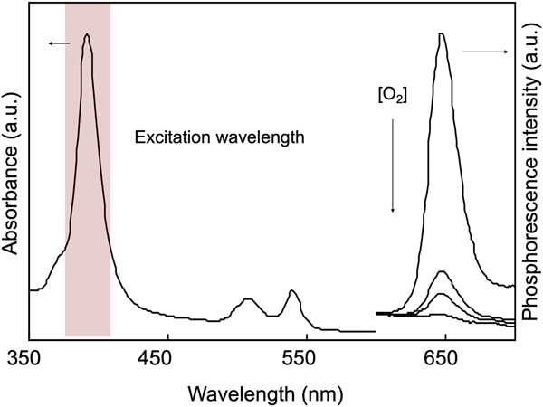
Absorption and luminescence spectra of the PtTFP/PMSP coating overlayered with PVA are shown in Fig. 1. The absorption and luminescence spectra of the PtTFP/PMSP coating (the oxygen sensor) and the coating overlayered with PVA (the crack sensor) were the same because PVA was transparent and had no optical absorption at the wavelength. The Soret band of the platinum porphyrin at around 400 nm was selected as an excitation wavelength. The luminescence intensity of PtTFP/PMSP, the oxygen sensor, changed in <1 s to achieve equilibrium when the oxygen concentration was tuned by the gas blender. On the other hand, the luminescence intensity change in the PtTFP/PMSP laminated by the PVA crack sensor was slow; the original luminance was detected even after 1 h at different oxygen concentrations. This result suggests that PVA lamination is an effective barrier for oxygen molecules.
Absorption and luminescence spectra of PtTFP immobilized in PMSP coating under a series of oxygen concentrations.

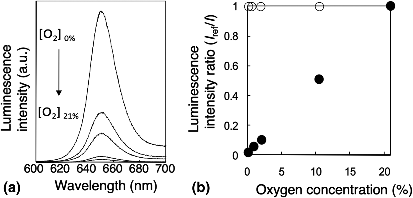
Stern–Volmer plots were obtained from a series of luminescence spectra (Fig. 2). The steep slope of Stern–Volmer plots for the PtTFP/PMSP oxygen sensor indicates the high and linear oxygen sensitivity. On the other hand, no inclination in the slope of the plots for the PVA-overcoated PtTFP/PMSP crack sensor coating suggests that the luminescence intensity was always high and stable under atmospheric conditions (21% oxygen). The luminescence activity of the coating maintained for 1000 h under irradiation light with 400 nm (15 mW/cm2).
(a) Luminescence spectra under a series of oxygen concentrations, (b) Stern–Volmer plots corresponding to luminescence spectra, PtTFP/PMSP mono-layer for the oxygen sensor (●), and laminated with PVA coating for the crack sensor (○).

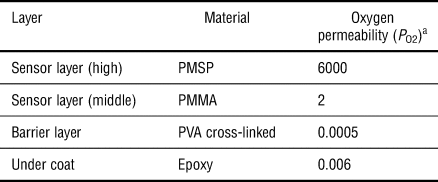
An important key in this sensor mechanism for crack visualization is the visual recognition of luminescence quenching by the invasion of oxygen to the oxygen sensor layer, which was caused by the destruction of the barrier layer by a crack. The oxygen permeabilities of the sensor and barrier layers adhered to one another should be very different, resulting in a drastic luminescence change when the layers were cracked for naked-eye inspection. The oxygen permeability of all the polymer materials used for laminate structures was measured. The permeability coefficients of oxygen (P O2) are given in Table I. PMSP used for the binder of the sensor layer showed an extremely high permeability of 6000 Barrer. PMSP is well-known as the highest gas-permeable polymer as a single component.[Reference Nagai, Masuda, Nakagawa, Freeman and Pinnau22] The ratio of the oxygen permeabilities of PMSP to PVA, which was used for the oxygen barrier layer with cross-linked for water resistance in this study, was 1.0 × 10⁶, and the ratio of the oxygen permeabilities of PMSP to epoxy-type undercoat was 1.0 × 10⁵. The gas barrier property of PVA was extremely high and the epoxy-type undercoat also exhibited a high gas barrier property, suggesting that this crack sensor system can possibly be incorporated into commercial paint products when the system reaches a level of practicality in the future.
Oxygen permeability of each layer of crack sensor paints.

a 1 Barrer = [cm3(STP)·cm/cm2·s·cmHg] × 10−10.
Evaluation of performance of crack sensor coating
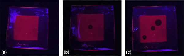
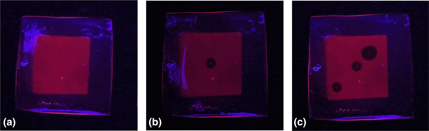
To evaluate whether the luminescence from the coating was quenched at a level where visual detection was possible when the barrier layer was damaged, a free-standing triple-layered coating combined with a PVA barrier, PtTFP/PMSP sensor, and PVA barrier was prepared. Figure 3 shows how the luminescent images changed after the barrier layer became damaged. The coating emitted intense visible light recognizable by the naked eye or a smartphone camera under irradiation under the original state [Fig. 3(a)]. When the coating was stuck by 18 G needles (outer diameter ϕ = 1.28 mm), oxygen quenching occurred and rapidly spread from the damaged point to some extent. Comparison between Figs. 3(a) and 3(b) clearly illustrates the damaged point. The size of the quenched area was larger than the actual damage and tended to depend on the size of damage. Figure 3(c) is an example of the size effect of the damage on the barrier layer using another needle (18 G needle at down left and 16 G needle at upper right, outer diameter ϕ = 1.68 mm). The relationship between quenching and the damaged area is quantitatively analyzed. A coating with the same composition was subjected to an optical measurement using a metric 12-bit CCD camera to analyze the luminescence distribution and emission behavior when the coating was damaged. The luminescence intensity ratio of the healthy area to the damaged area was more than 3.0 (see detail Fig. S1–S3 in Supporting Information). The index of the luminescent oxygen sensor estimated by the luminescence intensity of the maximum luminescence intensity I 0 (0% O2)/minimum luminescence intensity (100% O2) ratio is reported as >3.[Reference MacCraith, MacDonagh, O'Keeffe, Keyes, Vos, O'Kelly and MacGilp26] In this experiment, the healthy area was regarded as I 0 and the damaged area was regarded as I 21 (21% O2), which was high enough to apply it to the practical products, as a result of the reliable PtTFP/PMSP-based oxygen sensor.
Crack visualization by luminescent oxygen sensor coating with the gas barrier layer. (a) Healthy condition, (b) and (c) damaged by needle.
Crack sensing on a concrete material
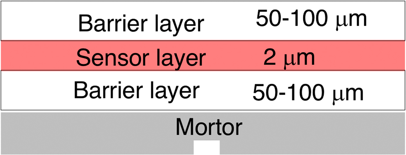
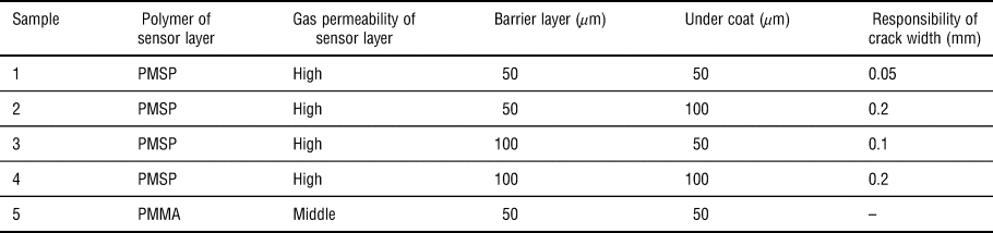
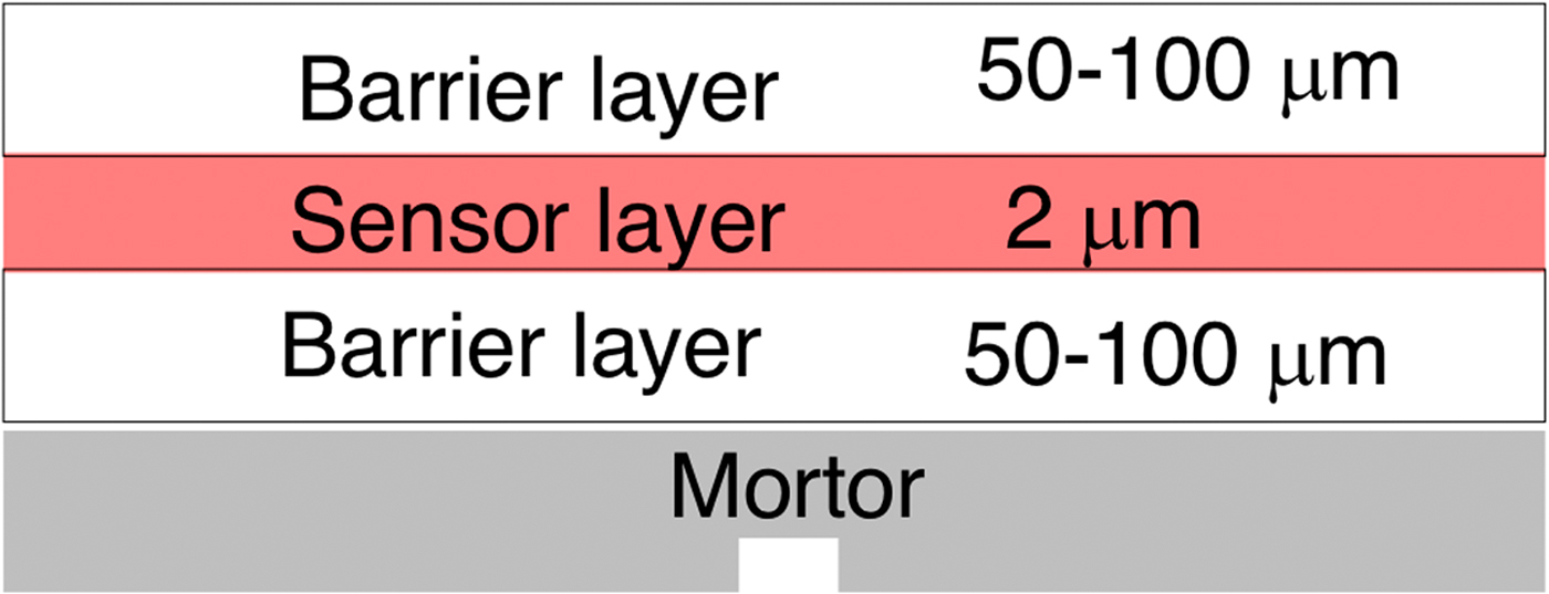
Figure 4 represents the diagram of the laminated crack sensor on the mortar concrete test piece. Table II shows the evaluation of the crack responsibility, verifying the thickness of the barrier layers. The crack sensor, composed of PMMA as the binder of the sensor layer, was used as the control sample (P O2 = 2 Barrer) because PMMA was a common binder for oxygen sensors. The luminescence of sample 1 prepared with PVA as both the top-and under-coating, 50 µm thick, was quenched for a 0.05 mm-width crack, which is difficult to confirm by the naked eye. The quenched area in the luminescence image on the concrete test piece was also larger than the actual crack width, which resulted in remarkably high visibility, allowing easy confirmation by eye or digital image. A width crack of 0.05 mm was detected by this sensor in the combination of a 50 µm-thick undercoat barrier, 2 µm-thick oxygen sensor, and 50 µm-thick top-coat barrier. The quenched area did not grow larger than a certain limit under continuous irradiation. In the case of the 0.05 mm-width crack, the destruction inside the triple-layered sensor coating occurred only at the undercoat barrier layer and did not reach the sensor or top-coat barrier layer. The crack of the mortar concrete might cause the destruction of the undercoat barrier layer contiguous with the concrete because the thickness of PVA undercoating was thin. A thicker barrier thickness corresponded to a larger crack width that the sensor could detect. For example, for a thickness of 50 µm for the undercoat and 100 µm for the top coat (sample 2), the luminescence quenching was monitored at a width of 0.1 mm. PVA undercoat layers demonstrated tensile deformation when the mortar concrete test piece caused a crack, which resulted in the reduced response to the crack in direct ratio to the thickness of the undercoat. Not only the thickness but also the materials of the barrier layers may affect sensitivity to the crack width. Materials for the barrier layer, PVA in this study, could possibly be replaced by a practical paint structure to the target width of the crack.
Crack sensor coating carried out on mortar concrete test piece.
Performance of crack sensor paint controlled by layered structure.

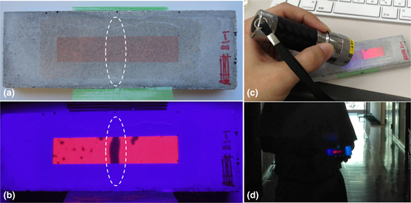
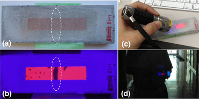
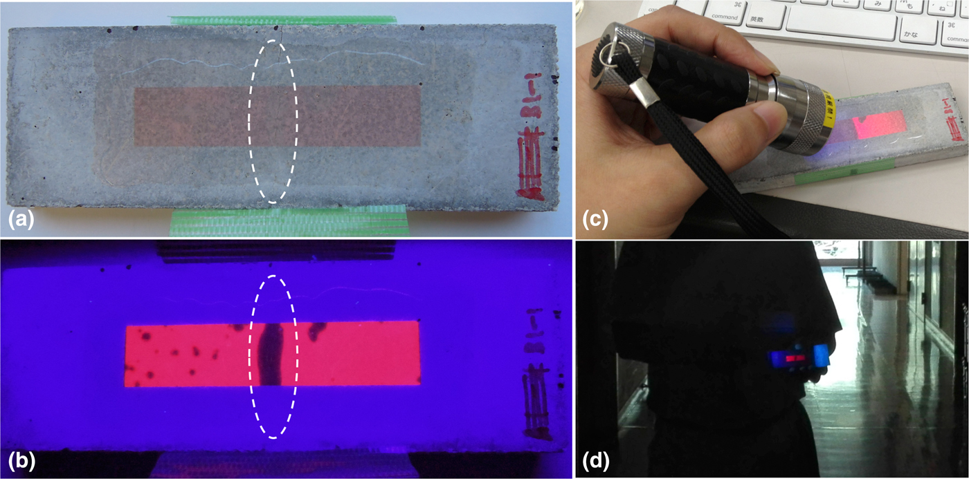
The test piece after the tensile test was carefully extracted from the tensile testing machine and placed on a solid plate to prevent further cracking. The test piece emitted strong luminescence along with the crack once again under irradiation after unloading the tension, which signifies that this sensor coating left a crack history. In the point of view of actual periodic inspection, a historical record is an essential property. When the test piece was irradiated again, the quenched area of the luminescence image was larger than the original luminescence image; however, continuous irradiation led to the quenched area of the luminescence image occupying the original range. Oxygen energy transferred from irradiated PtTFP and ground-state oxygen supplied from the crack of the barrier layer struggled with each other to reach an equilibrium state. A luminance contrast between the healthy area and the dark area, quenched by oxygen from a crack, was high enough to be distinguished by a picture taken with mobile phone, even from a distance of 5 m (Fig. 5).
Picture of mortar concrete test piece (a) under natural light, (b) under dark with UV light, (c) under natural light with UV light, and (d) captured from a distance of 5 m using smartphone camera.
Conclusion
A crack sensor paint system was developed using luminescent oxygen sensor materials designed as a triple-layered coating. The coating emitted strong luminescence under UV irradiation and fine cracks were visualized as 0.1 mm by luminescence quenching, with oxygen invaded through the crack, although it was difficult to check by the naked eye. The luminescence and quenched image were clear enough for the eye or smartphone camera. The response range of the crack width could be controlled by tuning the thickness or the materials of the layered paint system. The coating enhanced fine crack visibility in dark to find damage on a concrete structure from a distance. The paint system could contribute to the maintenance of social infrastructure all over the world through the tuning of the response range to target the crack width, which should be repaired according to the laws of each country, for example, 0.2 mm in Japan.[27] The crack detection paint also has a cost advantage because the gas barrier materials are already used in practical paint systems, and the amount of the oxygen sensor complex is very low. The gas barrier property of general epoxy-type concrete undercoat was high enough to show strong luminescence. A realistic step-up to practical applications can be expected by the insolubilization of each layer, by cross-linking, for example.
Supplementary material
The supplementary material for this article can be found at https://doi.org/10.1557/mrc.2019.38
Acknowledgments
This work was partially supported by JSPS Grant-in-Aid for Young Scientists (A) 30468871, (B) 22760334, and the Maeda Engineering Foundation Grant. The author thanks Prof. H. Sakaue and Dr. K. Morita for their discussions regarding this work.