1. INTRODUCTION
In the last decade, the generation of laser pulses in the multi-terawatt (or even petawatt) power range is possible with compact chirped-pulse amplification (CPA) systems, and the extreme light infrastructure (ELI) will be able to generate intensities in the range of 1025–1026 W/cm2 (Gerstner, Reference Gerestener2007). In CPA table-top lasers, the laser intensities increased up to I = 1022 W/cm2, and electric field strengths of more than 1014 V/m were obtained (Umstadter, Reference Umstadter2003). Particles can be accelerated in these high gradient fields and used for various applications, including transmutation of cheep and hazardous materials of long-living radioactive wastes to valuable radioisotopes (Sadighi-Bonabi & Kokabee, Reference Sadighi-Bonabi and Kokabee2006). The extremely high electric field makes the laser wakefield acceleration method attractive for the development of a new generation of accelerators (Geddes et al., Reference Geddes, Toth, Van Tilborg, Esarey, Schroeder, Cary and Leemans2004). In the laser wakefield scheme, the ponderomotive force associated in the front and the rear sides of a short laser pulse expels the plasma electrons from the regions where the laser field is the most intense (Malka et al., Reference Malka, Lifschitz, Faure and Glinec2006). The induced charge separation between the electrons and the ions gives rise to a space charge field and a plasma wave (Robson et al., Reference Robson, Simpson, Clarke, Ledingham, Lindau, Lundh, Mccanny, Mora, Neely, Wahlstro, Zepf and McKenna2007). Large amplitude plasma waves are generated by this ponderomotive force in the laser wakefield accelerator (LWFA). The ponderomotive force F p is given by F p ≈ −∇a 2, where α is the laser pulse envelope. The acceleration gradient resulting from the charge displacement is reported to be about 100 GV/cm when plasma density is 1018 cm−3 (Hemker et al., Reference Hemker, Hafz and Uesaka2002).
In the linear regime, this mechanism is more efficient when the pulse duration of the laser is on the order of the plasma frequency, and it is called resonant wakefield. The resonant wakefield regime creates a controllable and linear accelerating structure. In nonlinear regimes, background plasma electrons can be trapped in the plasma wave bucket and accelerated up to GeV (Karmakar & Pukhov, Reference Karmakar and Pukhov2007; Leemans et al., Reference Leemans, Nagler, Gonsalves, Toth, Nakamura, Geddes, Esarey, Schroeder and Hooker2006; Glinec et al., Reference Glinec, Faure, Pukhov, Kiselev, Gordienko, Mercier and Malka2005; Koyama et al., Reference Koyama, Adachi, Miura, Kato, Masuda, Watanabe, Ogata and Tanimoto2006; Lifshitz et al., Reference Lifschitz, Faure, Glinec, Malka and Mora2006). One of the most important applications for such short ultra-intense laser pulses is the acceleration of charged particles, both electrons and ions (Flippo et al., Reference Flippo, Hegelich, Albright, Yin, Gautier, Letzring, Schollmeier, Schreiber, Schulze and Fernández2007; Hegelich et al., Reference Hegelich, Albright, Cobble, Flippo, Johnson, Letzring, Paffett, Ruhl, Schreiber, Schulze and Fernandez2006; Yin et al., Reference Yin, Albright, Hegelich and Fernndez2006; Roth et al., Reference Roth, Brambrink, Audebert, Blazevic, Clarke, Cobble, Cowan, Fernandez, Fuchs, Geissel, Habs, Hegelich, Karsch, Ledingham, Neely, Ruhl, Schlegel and Schreiber2005; Nickles et al., Reference Nickles, Ter-Avetisyan, Schnuerer, Sokollik, Sandner, Schreiber, Hilcher, Jahnke, Andreev and Tikhonchuk2007; Ruhl et al., Reference Ruhl, Cowan and Pegoraro2006). The self-modulated laser wakefield (SMLWF) (Esarey et al., Reference Esarey, Krall and Sprangle1994) and the forced laser wakefield (FLWF) (Malka et al., Reference Malka, Fritzler, Lefebvre, Aleonard, Burgy, Chambaret, Chemin, Krushelnick, Malka, Mangles, Najmudin, Pittman, Rousseau, Scheurer, Walton and Dangor2002) are the well known nonlinear regimes. In the SMLWF regime, the envelope of the laser pulse can modulate at the plasma wave period and drives the wakefield properly with its ponderomotive force via Raman forward scattering instability. In the FLWF regime, the laser pulse is compressed by group velocity dispersion during the excitation of the plasma wave, and drives the plasma wave to very high amplitude. To obtain accelerated electrons with higher efficiencies, the electrons should be injected in the correct phase of the plasma wave. There the injection of background plasma electrons is possible instead of an external electron injector (e.g., a lilac) when wave-breaking occurs (Tomassini et al., Reference Tomassini, Galimberti, Giulietti, Giulietti, Gizzi, Labate and Pegoraro2004). By using the steepened density profile, the wave-breaking injection can be fast. A well collimated, ultra short MeV electron bunch is obtained due to the transverse wave breaking (Zobdeh et al., Reference Zobdeh, Sadighi-Bonabi and Afarideh2008b, Reference Zobdeh, Sadighi-Bonabi and Afarideh2008c, Reference Zobdeh, Sadighi-Bonabi, Afarideh, Yazdani and Rezaei Nasirabad2008d) by using a shock wave driven with the irradiation of laser prepulse (Hosokai et al., Reference Hosokai, Kinoshita, Ohkubo, Maekawa, Uesaka, Zhidkov, Yamazaki, Kotaki, Kando, Nakajima, Bulanov, Tomassini, Giulietti and Giuliett2006). In recent experiments and PIC simulations (Malka et al., Reference Malka, Lifschitz, Faure and Glinec2006), generation of quasi-monoenergetic electrons has been reported, A free cold plasma electrons cavity (bubble) behind the laser pulse is observed (Faure et al., Reference Faure, Glinec, Pukhov, Kiselev, Gordienko, Lefebvre, Rousseau, Burgy and Malka2004). The following features are absent in the ordinary regime of laser wakefield acceleration (Kostyukov et al., Reference Kostyukov, Pukhov and Kiselev2004; Gordienko & Pukhov, Reference Gordienko and Pukhov2005; Esarey et al., Reference Esarey, Sprangle, Krall and Ting1996; Pukhov et al., Reference Pukhov, Gordienko, Kiselev and Kostyukov2004): (1) a cavity free from cold plasma electrons is formed behind the laser pulse instead of a periodic plasma wave; (2) a dense bunch of relativistic electrons with a quasi-monoenergetic spectrum is self-generated; (3) the laser pulse propagates many Rayleigh lengths in the homogeneous plasma without a significant diffraction. The cavity behind the laser pulse is shown by shadowgraphs (Mangles et al., Reference Mangles, Thomas, Kaluza, Lundh, Lindau, Persson, Tsung, Najmudin, Mori, Wahlstro and Krushelnick2006) and PIC simulation (Pukhov & Meyer-ter Vehn, Reference Pukhov and Meyer-Ter Vehn2002; Faure et al., Reference Faure, Glinec, Pukhov, Kiselev, Gordienko, Lefebvre, Rousseau, Burgy and Malka2004). Quasi-monoenergetic electron beams were generated from intense laser pulses in various gas targets (Chen et al., Reference Chen, Unick, Vafaei-Najafabadi, Tsui, Fedosejevs, Naseri, Masson-Laborde and Rozmus2008).
In this work, we describe analytically the new ellipsoid model (Zobdeh et al., Reference Zobdeh, Sadighi-Bonabi and Afarideh2008a) to be used instead of the previous spherical cavity. In fact, the cavity shape is not exactly a sphere, and this is a defect in previous works (Gordienko & Puhkov, 2005; Kostyukov et al., Reference Kostyukov, Pukhov and Kiselev2004). Some deviations between shadowgraphs, PIC simulation, and analytical calculation results are reported because of the spherical estimation for the cavity shape. Appropriate conditions of forming an ellipsoid cavity are obtained. We have evaluated fields inside of this cavity and the energy spectrum for relativistic trapped electrons, and obtain energy and electron gain when self-focusing is considered. In the experimental part of this work, a 20 TW power and 30 fs laser pulse was focused on a pulsed He gas jet (Sadighi-Bonabi & Zobdeh, Reference Sadighi-Bonabi and Zobdeh2008). We have focused the laser pulse in the best matched point above the nozzle gas to obtain a stable ellipsoid bubble. How to find the optimum point will be described in analytical details.
2. CAVITY STABILITY AND THE ELECTRON TRAJECTORY
Considering in the electron dynamic equation the internal electromagnetic fields and the ponderomotive force of the laser propagation, we obtain:

where E p, µ, r,  , θ,
 , Q i, e, and ɛ0 are ponderomotive force, electron mass with approximately laser group velocity, radial component, derivative of radial component, tangential component, derivative of tangential component, average ion charge in the cavity, electron charge, and cavity dielectric constant, respectively. Eq. (1) can be separated into radial and tangential components. We can assume for the electron motion on the cavity sheath that the radius vector r sweeps out an angle dθ in a short time dt. If A is defined as the area swept, then we have dA =( 1/2)r 2dθ, dA/dt = (1/2)r 2. We, as usual, define the system's constant angular momentum by ℓ = |L| = µr 2. So, one has

then,

We assume that the solution r(t) can be written as r = r(θ), where θ = θ(t). Then we seek a solution in the form u(r) = 1/r(θ(t)):

Recalling that ℓ = µr 2 and r = 1/u, we have

It follows

where k = −e/µ · Q i/4π ∈0,
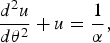
with
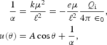
so we get
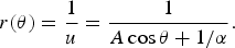
Finally, if we set A = ɛ/α, then: we obtain
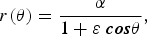
where α and ɛ are constant. Similar considerations and derivations may also be found in classical dynamics of particles and systems (Marion & Thornton, Reference Marion and Thornton1998).
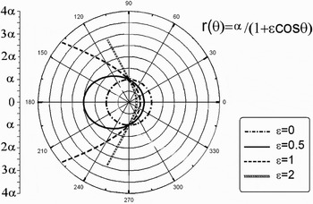
From Eq. (7) follows, that the electron trajectory is a hyperbola if ɛ > 1, a parabola if ɛ = 1, an ellipse if 0 < ɛ< 1, and a circle if ɛ = 0. This is shown in Figure 1. For the case of the ellipsoid trajectory (ɛ ≠ 1 and 0 < ɛ< 1), we define the length of the ellipse's long axis = 2a e, then 2a e = r(0) + r(π) = 2α/1 − ɛ2 and r(θ) = a e(1 − ɛ2)/1 + ɛ cosθ.
Electron trajectory for different eccentricities ɛ: hyperbola if ɛ > 1, parabola if ɛ = 1, ellipse if 0 < ɛ< 1 and circle if ɛ = 0.

3. DISCUSSION OF THE TRAJECTORY
In Eq. (6), the constant “A” can be defined by the initial condition of the electron. It means the trajectory will depend strongly on the initial condition. For an electron far from the bubble, θ = 0, r → ∞, r = α/(1 + cosθ) one has a parabola as a trajectory. For the electron at the margin of the bubble at θ = 0, r = R, it yields r = α/1 − ((α/R) − 1)cos θ, (α/R) ∝ − (l 2/μR 2)/eQ i/4πɛ0R, where R is the radius of the bubble, and α/R is proportional to the ratio of electron energy to electrostatic energy. So the electron trajectory will depend on α/R. The electron has a circular trajectory if (α/R )− 1 = 0, or α/R = 1. The electron has an ellipse trajectory if 0 < (α/R) − 1 < 1, or 1 < (α/R) < 2. The electron trajectory is influenced by its position and energy, and the electrostatic potential of the cavity.
4. ELECTROMAGNETIC FIELDS AND ELECTRON ENERGY INSIDE THE CAVITY
We consider a cavity moving in plasma. Ions are immobile in the cavity while the cavity runs with the relativistic velocity υ0 ≈ 1 along the x-axis. The ion dynamics are neglected because the cavity dimensions are assumed to be smaller than the ion response length ≈ c/ωpi, where ωpi = (4πe 2n 0/M) is the ion plasma frequency, and M is the ion mass. To calculate the fields, we write the Maxwell equations in terms of potentials using the following convenient gauge A x = −φ. According to the calculations of Kostyukov et al. (Reference Kostyukov, Pukhov and Kiselev2004) we get:
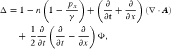

Here we use the wakefield potential Φ = A x −φ instead of the scalar one, and p is the electron momentum. We use dimensionless units, normalizing the time to ωp−1, the lengths to c/ωp, the velocity to c, the electromagnetic fields to mcωp/|e| and the electron density n to the background density n 0. If we use a quasi-static approximation assuming that all quantities depend on ξ = x − v 0t instead of x and t.
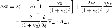
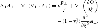
Inside the cavity we assume (n = 0), then we get


The solution of basic Maxwell Eqs. (9) and (10) inside an ellipsoid electron cavity is:
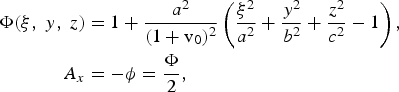
where
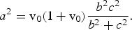
We assumed that the potential on the surface of the ellipsoid is constant and Φ = 1. Eq. (15) has an important result, which is one of the most attractive features of ellipsoid regime, and it is the elongation of the ellipsoid bubble in the direction of relativistic movement for the fixed amount of b and c axis of the ellipsoid.
Where a, b, and c are the semi-axes of the ellipsoid, with azimuthally symmetry about x axis we have:

a′2 = 2/(v0 (1 + v0)). Here the velocity of bubble is v0 and contrary to Pukhov et al. (Reference Pukhov, Gordienko, Kiselev and Kostyukov2004), we did not set v0 = 1. The electromagnetic fields inside the relativistic cavity are:
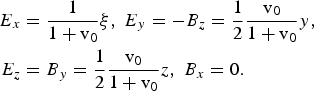
If we substitute v 0 = 1 then the model will reduce to the spherical regime.
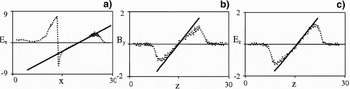
As seen from the PIC results in Figure 2, it is evident that the slope of E y is less than one-fourth, and it is inconsistent with Eq. (14) since we always have v0 < 1. The calculated distribution of electromagnetic fields is close to the one observed in the three-dimensional PIC simulation (Fig. 2). This was a defect of spherical model and it was mentioned earlier by Pukhov et al. (Reference Pukhov, Gordienko, Kiselev and Kostyukov2004) and Kostyukov et al. (Reference Kostyukov, Pukhov and Kiselev2004). The small deviation from the analytically calculated field distribution is because the cavity shape is not exactly a sphere (Pukhov et al., Reference Pukhov, Gordienko, Kiselev and Kostyukov2004; Kostyukov et al., Reference Kostyukov, Pukhov and Kiselev2004).
Space distribution of the electromagnetic fields normalized to mcωp/|e| at the time instance when the laser pulse has passed 25c/ωp : (a) E x as a function of x; (b) B y as a function of z; (c) E z as a function of z. The PIC simulation results are shown by dashed lines while the analytical results are shown by solid lines. The coordinates are given in c/ωp (Pukhov et al., Reference Pukhov, Gordienko, Kiselev and Kostyukov2004).

The Lorentz force acting on a relativistic electron with v = vx = v0 inside the cavity is
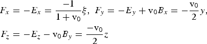
The wake potential Φ can be considered with vx = v0 as the potential of the Lorentz force on the electron. The Lorentz force with vx = −v0 is:

The dynamics of electron acceleration in an ellipsoid cavity can be analyzed using the Hamiltonian formulation. The general one-dimensional Hamiltonian of a charged particle in an electromagnetic field is

where p c is the particle canonical momentum and φ is the scalar potential. The Hamiltonian can be split into two parts by expanding it in the power of p c2. The first part determines the longitudinal motion and the second part determines the transverse motion. We obtain the longitudinal Hamiltonian and consider only the x dimension

Here p x is the momentum in the x direction. We have used the wake potential and the initial conditions p x = α= 0 and Φ = 1 are applied. With the assumption p x » γ0 and α ≈ 0 this can be written as:

The maximum energy of the accelerated electrons peaked at the cavity center is given by the following equation:
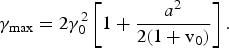
If we insert for a the value found from Eq. (15), then we get

The result of this equation is very important. It shows that the maximum energy for a defined ellipsoid with fixed dimension along the y and z directions at higher speed of bubble increased due to the dependence of the energy on the bubble velocity. This is because of the dependence of the magnitude of a on v 0 and the elongation of the ellipsoid in the x direction Eq. (15). For b = c we have

This is similar to the results of the spherical model by Pukhov et al. (Reference Pukhov, Gordienko, Kiselev and Kostyukov2004).
As a consequence, we can see that the ellipsoid bubble model is the better representative of the relativistic electron energy. It shows that at higher speeds, the electrons will have higher energies. If a = b = c and v0 = 1 then Eqs (23) to (25) will be the same as in the spherical model of Pukhov et al. (Reference Pukhov, Gordienko, Kiselev and Kostyukov2004). As a result, we can conclude that the spherical model is a special state of ellipsoid model introduced in this paper for the first time.
The initial condition to obtain an ellipsoid cavity is defined by the laser-plasma parameters. According to the previous discussion in Section 3, the electron trajectory is influenced by the ratio of its energy to the cavity electrostatic potential. When the ellipsoid cavity regime is obtained (0 < ɛ< 1), the electron energy in the ellipsoid cavity has a low spread spectrum and its maximum amount in the center depends on the semi-axis a elongation during the laser pulse propagation in experimental and PIC simulation results.
It follows that the electrons of the bunch have equal energy, and the ellipsoid cavity holds the electron bunch in a quasi-monoenergetic regime better than previous spherical models. In the spherical model, the energy of the accelerated electrons' peak is given by (Kostyukov et al., Reference Kostyukov, Pukhov and Kiselev2004)
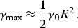
In this equation, R is the radius of the spherical bubble, and γ0 is defined as γ0 = (1 − v0)−1/2. v0 is the laser pulse group velocity (Kostyukov et al., Reference Kostyukov, Pukhov and Kiselev2004). Eq. (26) shows that the electron bunch energy is strongly related to the transverse radius of the cavity, and during the laser propagation, because of the longitudinal elongation of the cavity, the energy peak spectrum will spread. But in the ellipsoid model, according to Eq. (23), the longitudinal elongation (a) influences the energy spectrum of the electron bunch. This is an improved version of our previous works (Zobdeh et al., Reference Zobdeh, Sadighi-Bonabi and Afarideh2008b, Reference Zobdeh, Sadighi-Bonabi and Afarideh2008c).
5. EXPERIMENTAL SETUP AND QUASI-MONOENERGETIC ELECTRON RESULT
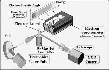
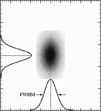
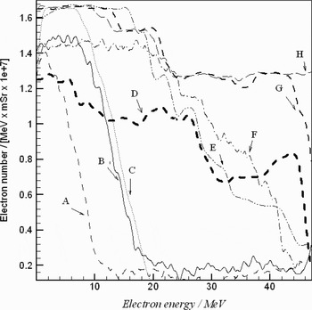
In order to generate a laser acceleration wakefield, a 20 TW, 30 fs laser pulse based on the Ti-Sapphire CPA laser system has focused onto a supersonic He gas jet with a f/5 off-axis gold-coated parabolic mirror. The scheme of the experimental setup is shown in Figure 3. The focal spot size and the focusing location at different positions from the beginning of the gas jet are measured by using a charged coupled device (CCD) camera with a microscope objective lens. The typical spot size diameter was equal to 11 µm horizontally and 12 µm vertically at full width at half-maximum (FWHM) that is shown in Figure 4. The gas target stagnation pressure (plasma density) can be adjusted by a solenoid supersonic pulsed valve. The nozzle that produced the gas jet had a 2 mm cylindrical shape hole. The density distribution of the gas jet is measured by a Mach-Zehnder interferometer. The electron beam energies are detected by using a permanent magnet on image plates (Tanaka et al., Reference Tanaka, Yabuuchi, Sato, Kodama, Kitagawa, Takahashi, Ikeda, Honda and Okuda2005; Hutchinson, Reference Hutchinson1987). We changed the laser power from 1 TW to 18 TW, and the plasma density from 2 × 1019 cm−3 to 14 × 1020 cm−3. Most of the electron energy spectrums possess a Maxwellian distribution that is shown in Figure 5.
The experimental setup is shown. The 30 fs laser pulse is focused into the He gas jet using the f/5 off-axis gold-coated parabolic mirror. The gas target density can be adjusted by a solenoid supersonic valve. Electron beam energies are detected by using a permanent magnet on the image plates.

Two dimensional of the laser beam distribution recorded by CCD camera. The typical horizontal and vertical dimensions of laser spot diameters at full width half-maximum (FWHM) were equal to 11 µm and 12 µm respectively.

Quasi-Maxwellian electron energy results at various laser powers and the maximum density of plasma density profiles, A: 1 TW, 2 × 1019 cm−3, B: 3.5 TW, 3 × 1019 cm−3, C: 4.4 TW, 4/5 × 1019 cm−3, D: 6.3 TW, 2.8 × 1020 cm−3, E: 9.5 TW, 6.3 × 1020 cm−3, F: 10.2 TW, 7.7 × 1020 cm−3, G: 15.5 TW, 9.2 × 1020 cm−3, H: 18 TW, 13.7 × 1020 cm−3.

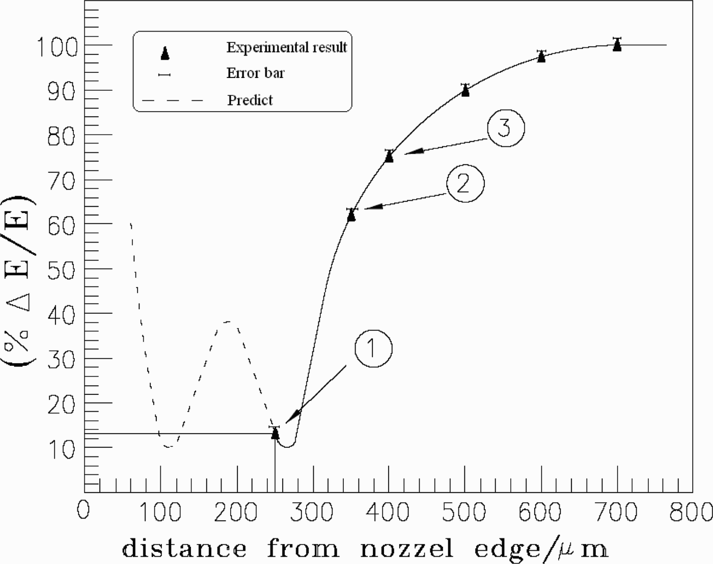
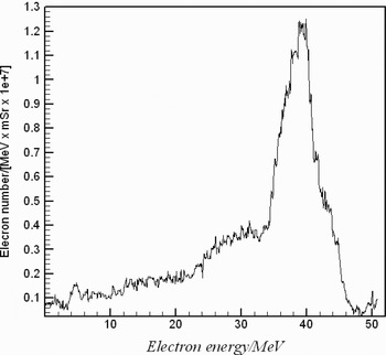
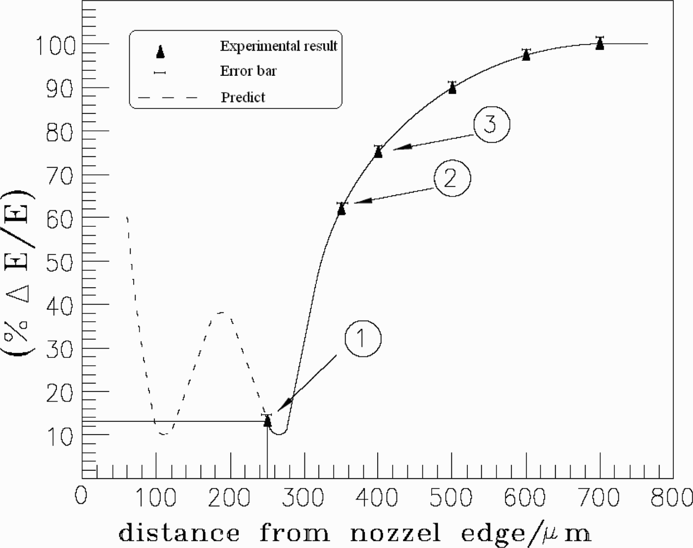
When the power of the laser was 16.6 TW (500 mJ) and the maximum density of the plasma amounted to 14 × 1019 cm−3, we observed the quasi-monoenergetic electrons by focusing of the laser beam along the axis of laser propagation, which was one millimeter above the edge of the nozzle. By focusing of the laser beam at different positions from the beginning of gas jet (Fig. 3), we obtained various electron energy profiles. In this experiment, we did not observe any evidence of bubble formation resulting in monoenergetic electrons up to 200 ± 5 µm from the beginning of gas jet. At 250 ± 5 µm (at the point 1 of Fig. 6), we obtained quasi-monoenergetic electrons that are shown in Figure 7. Figure 6 show that one can obtain high energy electrons with narrower energy distribution by better and precise focusing. When we moved further along the laser beam, the profile of the electrons changed more to the quasi-Maxwellian shapes (at points 2 and 3 of Fig. 6). Under the conditions of this experiment (focusing radius of 5.5 µm), points less than 600 µm showed 100% distribution of electron energy as we can see in Figure 6.
Electron energy percentage distribution (% ΔE/E), for different focused distances along the axis of laser propagation .The laser power is 16.6 TW and the maximum of the plasma density profile is 14 × 1019 cm−3. The solid part of the curve is produced by experimental measurement and the dashed part is plotted from the predicted parameters of Figure 8.
The quasi-monoenergetic electron spectrum is shown. The laser power is 16.6 TW and the maximum of the plasma density profile is 14 × 1019 cm−3. The laser beam was focused along the axis of laser propagation in 250 ± 5 µm distance 1 mm above the nozzle edge. The related image plate is shown at the top of the figure.

6. DISCUSSION
For the condition of cavity formation, at the initial state of laser-plasma interaction, the ponderomotive potential of the laser pulses determines the cavity shape. If we assume the cavity shape in this situation to be a sphere, the electron sheath of the cavity feels the Lorentz force, which is nearly balanced by the laser ponderomotive force. The transverse radius R of the cavity can thus be estimated from the equation (Kostyukov et al., Reference Kostyukov, Pukhov and Kiselev2004)

The ponderomotive force is written for the laser pulse which is spherical and circularly polarized. The electron kinetic energy is neglected when we compare it to the ponderomotive potential. For the laser pulse, at relativistic intensity, we have a Gaussian profile for the intensity distribution. The dimensionless amplitude a(r) will be focused to a spot size ω0 by a Gaussian profile (Gibbon, Reference Gibbon2005)
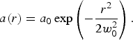
Substituting Eq. (28) into Eq. (27) and converting the dimensionless R to r, one obtains for the bubble radius
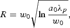
where λp is the wavelength of plasma. The effective ponderomotive potential is considered when the laser pulse length is on the order of half of the plasma wavelength. For the cavity regime condition, we also have cτ ≤ R (where τ is laser pulse duration). By consideration of SMLWFA, cτ = nR is the most stable cavity condition (Hidding et al., Reference Hidding, Amthor, Liesfeld, Schwoerer, Karsch, Geissler, Veisz, Schmid, Gallacher, Jamison, Jaroszynski, Pretzler and Sauerbrey2006; Amthor, Reference Amthor2006). So the stable condition can be obtained for R = mλp/2, where n and m are positive integer numbers.
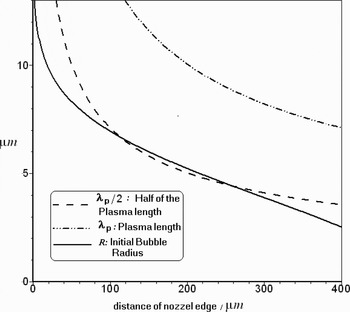
We have assumed a Gaussian plasma density distribution of the nozzle gas, and considered a slowly steepened profile with n = Lz + n 0 for the beginning regions of the plasma over the nozzle. Here L is a steepened plasma length and n 0 is the initial density. In this region, the wavelength of plasma will change as a function of Lz + n 0, and so the bubble radius may be calculated by Eq. (29). We have simulated this condition and shown that there are two particular points for laser focusing to obtain the optimum condition of cavity radius stability (Fig. 8).
The intersection points of λp(z)/2 and R (z) are the optimum points to produce stable bubbles to trap monoenergetic electrons. No crossings exist between higher order multiples of λp(z)/2, e.g., λp(z) and R(z).

We can conclude from Figure 8 that point 1 of Figure 6 corresponds to the bubble radius of only 4 µm, which is smaller than our 5.5 µm spot size radius. However, the first minimum point in Figure 6 corresponds to a bubble radius larger than 6.5 µm. Thus, we were not able to detect this point with our 5.5 µm laser beam spot size radius. Any distance shorter than the first minimum corresponds to a larger bubble radius, which we were unable to see. According to our aim to see larger bubbles to trap more electrons, we should produce larger laser spot sizes, which cause the reduction of our laser intensity below the critical relativistic intensities. As a result of that, to observe larger bubbles, one needs to have a laser beam with higher peak powers.
7. CONCLUSIONS
Previous cavity models such as the spherical model show some deviations in comparison with experimental and PIC results (Pukhov et al., Reference Pukhov, Gordienko, Kiselev and Kostyukov2004). In this work, we have presented an analytical calculation of the new elliptical model for the first time. We have shown that the electron trajectory can have the form of a hyperbola, parabola, and ellipse, and there are initial and final conditions for the ellipsoid cavity formation. A dense bunch of relativistic electrons with monoenergetic spectrum is self-generated, and the fields depend linearly on the coordinates. We have shown that the cavity elongation with fixed b and c semi-axis affected the maximum electron energy, so the quality of the electron beam is improved.
Finally, based on our experiments and calculations, we conclude the following two essential points. (1) In a defined density profile, only defined points can produce mono-energetic electrons beam. (2) In order to observe bigger bubbles for trapping more electrons, one has to use laser beams with higher powers to obtain larger focal spots with intensities larger than the critical relativistic intensities.
ACKNOWLEDGMENTS
The authors acknowledge the ministry of oil (IRI) for partial support of this work through contract No.1211 by Pars Oil and Gas Company, also the constructive cooperation of Prof. J. Zhong from CAS is deeply appreciated.