Introduction
The fourth generation (4G) long-term evolution (LTE) technology is quite mature nowadays. The multiple-input multiple-output (MIMO) technology has been widely applied to various mobile communication devices in an effort to provide faster transmission speed and more information transmission volume. The demand for bandwidth keeps rising with the development of multimedia and the increasing number of connected devices, and the current mobile communications adopting 4G technology are bound to face challenges. Therefore, various countries have embarked on the development of the fifth generation (5G) mobile networks technology in recent years. A 5G system should be able to demonstrate several capabilities, including supporting tens of thousands of users at the data transmission rates over 10 Gbps, large-scale concurrent connectivity, and sensor network deployment, with far better coverage, spectrum efficiency, and low latency than the ones of a 4G system. A 5G system requires more antennas in the same device, and a 5G network connection will be able to transmit data at a rate at least 10 times higher than the rate of a 4G network connection through the MIMO technology [Reference Fagbohun1, Reference Satinder and Babbar2].
Two kinds of frequency bands are classified in the field of 5G multi-antenna system, which are millimeter wave (mmWave) and sub-6 GHz. The mmWave frequency band may provide hundreds of channel bandwidths measured in MHz, which is expected to improve the data transmission rate when being compared to the one of an LTE system. An LTE system may only have tens of channel bandwidths measured in MHz. However, the application of mmWave is not an easy task. This is mainly limited by the path loss, transmitted signal susceptible to reflection fading, and shadowing effect in mmWave transmission, and outdoor high-speed handoff resulting in the degradation of the transmitted signal quality. The signals transferred via the mmWave band cannot even penetrate a wall. In addition, the mmWave band is also subject to waveform and energy consumption problems. The physical properties of the electromagnetic waves in the sub-6 GHz band do not suffer from the fast fading and shadowing effects of the ones in the mmWave band, which is an advantage of the sub-6 GHz band and makes it particularly suited for mobile communication systems [3].
Consumers have a particular preference for products that are thin and light, with narrow bezels or metal-backed covers when choosing mobile devices, and this has led many manufacturers to launch products with such appearance to attract consumers. The space in a device available for antennas has become smaller and smaller to keep up with this trendy, aesthetically pleasing, and screen-maximizing demand, so antennas need to be low-profile and small in size to meet these contemporary requirements for mobile communication products. Many miniaturized antennas with the LTE bands have been designed with MIMO technology to boost their transmission rates [Reference Li, Chen and Wu4–Reference Wong, Wan and Chen7], and the way in which inter-antenna isolation is optimized varies depending on the application device and the arrangement of antennas. However, as the transmission rates of LTE bands are lower than that of a 5G band, LTE antennas need to be larger in size. Therefore, 5G MIMO antenna systems become a better choice when the multi-antenna MIMO system is required in mobile devices.
A special emphasis is placed on the tight configuration of multiple antennas due to space constraints while still providing good isolation in the case of 5G MIMO antenna systems for mobile communication systems [Reference Ban, Li, Sim, Wu and Wong8–Reference Chen, Chou, Hsu and Li15]. Two antennas are configured with appropriate distance to optimize the isolation in the systems, with the distance between them of approximately 15–20 mm [Reference Ban, Li, Sim, Wu and Wong8, Reference Wong and Lu9]. There is also the technique for the optimization of isolation by adding a chip inductor to the branch end of the two antennas [Reference Wong and Chen10], so that only a chip inductor between the two antennas is required for the optimization, but this is relatively costly. Ref. Reference Chen, Chiang and Hsu11 presents a compact dual-band four-element MIMO antenna system. They are configured into two dual-antenna units. Within each unit, the two inverted-F antennas (IFAs) are arranged to be skew-symmetric with respect to the display ground plane, and their short-circuit points are brought close to each other to achieve the so-called short-circuit decoupling. In addition, the two units are mirror imaged of each other with a small gap in between and are connected by two decoupling chip inductors to form a high-isolation four-element MIMO antenna system. It is also possible to combine an IFA and an open slot antenna to form a hybrid dual antenna to achieve good isolation performance with only a very small interval of 2 mm between the two antennas [Reference Wong and Chang12]. There are also designs in which the 5G MIMO antenna array is placed on the side-edge frame of the handset [Reference Wong, Tsai and Lu13–Reference Chen, Chou, Hsu and Li15]. The decoupling technique is applied to the inherent shorted strips of the two antennas to effectively optimize the isolation between them with the two antennas placed diagonally and symmetrically opposite to each other on the system ground plane [Reference Wong, Tsai and Lu13–Reference Chen, Chou, Hsu and Li15]. Another design provides the idea of placing two antennas in a side-by-side, mirrored configuration on the bezel of the handset with the decoupling technique to optimize isolation [Reference Wong, Chen and Li16], which requires only 3 mm of distance between the two antennas for a good isolation performance. However, the antenna height needs to be 4.2 mm to cover the 3.3 GHz band of 5G network connections.
There is less literature on 5G multi-antenna design for laptops. However, the above-mentioned 5G multiple antennas for cell phones are not suitable for the configuration on laptops except for [Reference Wong, Tsai and Lu13–Reference Chen, Chou, Hsu and Li15] the ones which are diagonally and symmetrically mounted on the side bezel of the ground plane of a cell phone. The antenna profile height mentioned in [Reference Wong, Chen and Li16] has the room for further refinement, while the dual antenna mentioned in [Reference Wong and Chang12] can be configured in close proximity. The antenna profile height of 4 mm only covers the 3.5 GHz band of 5G network connections. The distances between the two antennas mentioned in [Reference Ban, Li, Sim, Wu and Wong8, Reference Wong and Lu9] still require refinement, while the antennas mentioned in [Reference Wong and Chen10, Reference Chen, Chiang and Hsu11] adopt chip inductors to optimize isolation in a relatively costly way.
A design of the dual-band 5G MIMO dual antenna for laptops was therefore proposed in the paper. The 5G dual-antenna unit is of a 29 × 2 × 3 mm3 three-dimensional structure with two antennas of the same structure and size. The antenna consists of a fed monopole and a shorted monopole, which are configured 4 mm apart and in the same direction to form a dual-antenna unit. The design is based on the premise that two antennas can be placed in close proximity to each other without the need for any isolation element. The two shorting points in the low-frequency resonant path of the two monopoles are designed at a distance greater than a quarter of the wavelength of the low frequency, which may effectively improve the isolation between them and the performance of the envelope correlation coefficient (ECC). A comparison of the properties of the MIMO antennas provided in this paper with those in the related literature mentioned above is shown in Table 1.
Comparison of the presented design with the recently reported 5G terminal MIMO antennas

Proposed MIMO antenna system structure
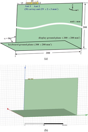
Figure 1 shows the overall configuration of the dual-band 5G MIMO dual antenna. The 5G MIMO dual antenna consists of two antennas of the same structure and size, named as Ant 1 and Ant 2. The display and keyboard ground planes are 300 × 200 mm2 each in size, which is approximately the size of display or keyboard for a typical 13-inch laptop on the market. The 5G MIMO dual antennas are placed 4 mm apart in a parallel way at the upper edge of the display ground plane and 15 mm away from the left edge, where a 0.2 mm-thick copper sheet is used on the display and keyboard ground planes for implementation and simulation. The 5G MIMO dual antennas cover 3300–3600 and 4800–5000 MHz dual-band operations for 5G communication with a performance better than 11 dB of inter-antenna measured isolation.
The overall structure of the proposed 5G MIMO antenna system. (a) Schematic diagram, (b) HFSS CAD model.

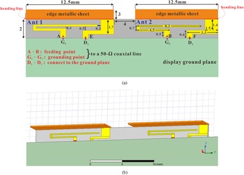
Figure 2 shows the detailed structure of the 5G dual-antenna unit, and the dual-antenna unit is composed of Ant 1 and Ant 2, which are arranged 4 mm apart and in parallel, with the dimensions of 29 × 2 × 3 mm3. The dual-antenna unit is printed on a 0.4 mm-thick, 29 × 2 mm2 FR4 substrate with a 3 mm bent copper sheet to form a three-dimensional structure with a relative dielectric constant of 4.4 and a loss tangent of 0.02. The 3 mm bent copper sheet is designed to utilize the space available at the top edge of the back cover of today's thin laptops for the configuration of the antenna, allowing the overall height of the antenna to be reduced for the maximum visual enjoyment of the screen. The 5G antenna consists of a fed monopole and a shorted monopole in a three-dimensional configuration with the size of 12.5 × 2 × 3 mm3. In the figure, point A and point B are the signal feeding points of Ant 1 and Ant 2 respectively and are connected to the inner conductor of the 50 Ω mini coaxial line. At the same time, the conductor outside the 50 Ω mini coaxial line is connected to the ground points G1 and G2 on the metal display ground plane, and D1 and D2 are the shorting points of the shorted monopoles of Ant 1 and Ant 2 respectively, which are linked to the metal display ground plane. Since Ant 1 and Ant 2 of the 5G antenna are the same in size and structure, the design process of the 5G antenna is described in the following section for Ant 1 only. Ant 1 generates two resonant modes to encompass the 3300–3600 and 4800–5000 MHz dual-band operations required for 5G communication, with the low-frequency mode contributed by the shorted monopole and the high-frequency mode contributed by both the fed monopole and the shorted monopole. By properly designing the coupling between the fed and shorted monopoles, the bandwidth for the operations of the antennas can be effectively increased.
The detailed structure of the proposed 5G MIMO antenna system. (a) Schematic diagram, (b) HFSS CAD model.

For these two antennas to be covered by the required bandwidth with good isolations, there must be some trade-offs in the design of the structural configurations. The dual-antenna design with monopole structure generates a quarter-wavelength resonance which is beneficial for the antenna downsizing. The dual-antenna unit is arranged side by side in the same direction and separated by 4 mm that the feeding points of the two antennas are separated by the shorting point of the shorted monopole antenna. The shorting points of the low-frequency resonant path (the shorted monopole antenna) of these two antennas are larger than a quarter of the wavelength of the low-frequency with appropriate bending. The strong current will be concentrated near the shorting point of the shorted monopole antenna when the low-frequency mode is excited, and the current flow from the ground to the feeding point of the other antenna will be reduced, achieving good isolation between the two antennas without adopting any isolation element. Compared with the dual-antenna elements of the monopole structure in [Reference Ban, Li, Sim, Wu and Wong8], this design does have a smaller size and wider bandwidth performance.
Results and discussion
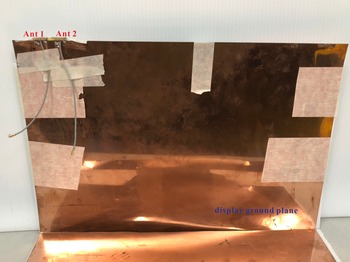
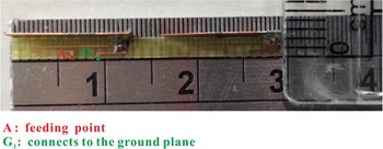
With the dimensions as indicated in Figs 1 and 2 for implementation and measurement, Figs 3 and 4 depict the overall configuration and the detailed structure of the 5G dual-antenna system respectively. The antenna system was simulated by using the ANSYS HFSS (Version 15) simulation software [17]. Figure 5 presents the S-parameters for the 5G MIMO antenna simulation and the measurement. The reflection coefficients of the dual antennas are set at less than −6 dB (i.e. VSWR = 3:1) as a standard, which is widely applied to current mobile communications devices [Reference Wong, Tsai and Lu13–Reference Wong, Chen and Li16]. It is easier to achieve the relevant measurement of the antenna efficiency in the actual measurement of the unit if the reflection coefficient between the antenna simulation and the actual measurement is less than −6 dB, while the transmission coefficients between the antennas are set at less than −10 dB based on relevant literature [Reference Wong, Tsai and Lu13–Reference Wong, Chen and Li16]. The impedance mismatch at the input ports of antenna is determined by the impedance between the antenna structure and the input at the feed. The figure clearly indicates that the dual antenna can encompass both the 3300–3600 and 4800–5000 MHz bands of 5G operation for both simulation and measurement purposes. The simulated isolation between the two antennas is approximately 10 dB in the low-frequency part of the band and just above 9 dB in the high-frequency band, but the measured isolation is better than 10 dB in both the low- and high-frequency bands.
Photo of the fabricated 5G MIMO antenna system integrated with the laptop.

The detailed structure of the 5G MIMO antenna system realization.

Simulated and measured S-parameters of the proposed 5G MIMO antennas system.

Measured results slightly differ from and get better compared to the simulated ones. The discrepancies and causes could be due to the fact that the additional mini coaxial cables and IPEX-to-SMA adaptors used in measurement causing loss are not considered in simulation. Moreover, the parameter variation of the FR4 substrate and the imperfection in fabrication could also be part of the reasons for the discrepancies.
The ECC is also an important reference parameter for MIMO antenna systems in addition to the isolation between the dual antennas. The system cannot recognize the difference between the two antennas and treats them as one-channel system when the ECC value for the two antennas is 1. An ECC of less than 0.5 is the standard for a channel system that can be applied in practice [Reference Vaughan and Andersen18]. The measured ECC was computed from the radiation-pattern-based formula [Reference Sarkar, Saurav and Srivastava19] given as

The measured amplitude and phase of the far-field radiation fields are used for the computation of ECCs. Figure 6 reveals the ECCs calculated from the measured complex E-field radiation patterns between the MIMO dual antennas with the ECC values in the 5G dual band being less than 0.12. This confirms the good channel independence of the two antennas in the 5G MIMO antenna system. It can be seen that the ECC values in the higher band is smaller than those in the lower band. This is because the wavelength in the higher band is relatively short. Therefore, the ECC values of two antennas at the same distance in the higher band are smaller than those in the lower band.
Calculated ECCs from measured radiation patterns of the 5G MIMO antenna system.

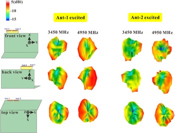
The three-dimensional total-power radiation patterns were measured at a newly established NSI 800F-10 far-field antenna test system in our existing antenna chamber with a sampling spacing of 15 degrees in both the θ and ϕ directions. Figure 7 shows the measured 3D radiation pattern of the MIMO dual antenna, which is presented here at 3450 and 4950 MHz, which are the central frequencies of the 3300–3600 and 4800–5000 MHz dual bands for 5G. The figure suggests that the 3D radiation pattern of Ant 1 and Ant 2 has as many zero points as the WLAN antenna at the upper edge of a conventionally configured laptop. It is also worth noting that the 3D radiation patterns of Ant 1 and Ant 2 are not similar at the same frequency points, which echoes the lower measured ECC values of the dual antenna in Fig. 6. Figure 8 shows the measured antenna efficiency of the MIMO dual antennas, and all the results are better than 40%.
Measured 3D radiation patterns of the two antenna elements at 3450 and 4950 MHz.

Measured antenna efficiencies for Ants 1 and 2.

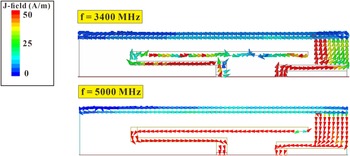
A current analysis was conducted on the Ant1 antenna structure to further verify the contribution of each mode to the 5G antenna. Figure 9 illustrates the current distribution of Ant1 at 3400 and 5000 MHz. These two frequency points are the best matching frequency points for simulation in the low and high bands, respectively. The graph demonstrates that when Ant 1 was operated at 3400 MHz, a strong current was distributed on the shorted monopole, thus verifying that the first mode was contributed by the shorted monopole. When Ant 1 was operated at 5000 MHz, there was a clear current distribution on both the fed and shorted monopole, thereby confirming that the second mode was contributed by both the fed and shorted monopole.
Ant 1 surface current distribution at 3400 and 5000 MHz.

Several parameters were analyzed with respect to the Ant1 structure in order to further analyze the contribution of each mode and validate the single-antenna design mechanism. First, the parameter a of the open-ended length for the shorted monopole was analyzed. Figure 10 shows a comparison of the reflection coefficient of parameter a. It is clear that when the open-ended length a of the shorted monopole was shortened from 12.5 to 8.5 mm, there was a clear upward trend in both low and high frequency modes, thus verifying that both the low- and high-frequency modes are contributed by the shorted monopole. Then a parametric analysis of the open-ended length c for the fed monopole was conducted. Figure 11 presents a comparison of the reflection coefficients for parameter c. It is clear in the graph that when the open-ended length of the fed monopole was reduced from 8 to 6 mm, and the high-frequency mode had a significant increase in frequency due to the reduction in the open-ended length of the fed monopole, thus confirming that the high-frequency mode contains a component contributed by the fed monopole. At the same time, the low-frequency mode also tended to upscale slightly, but not as much as the high-frequency mode, mainly due to the close proximity of the fed monopole branch to the shorted monopole branch, so there was some effect, but it was not as pronounced as in the high-frequency mode.
Comparison of simulated reflection coefficients for changes in parameter a.

Comparison of simulated reflection coefficients for changes in parameter c.

Closely spaced MIMO antenna system exploration
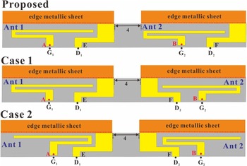
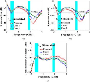
S-parameters, antenna efficiencies, and ECCs for different dual-antenna units were conducted to further understand the interaction of the different 5G dual-antenna units constituting the same structure and size of fed monopoles and shorted monopoles in Ant 1. The dual-antenna units in this analysis were also spaced at 4 mm apart. The proposed is the optimal structure for the 5G MIMO dual antenna suggested in this paper, case 1 is the reverse configuration of Ant 2 in the proposed, so that Ant 1 and Ant 2 are configured in a mirror-symmetrical way, and case 2 is the reverse of the open-ended length of the fed monopole in the case 1 configuration, so that Ant 1 and Ant 2 are also configured mirror-symmetrically. Figure 12 is the schematic diagrams of the proposed, which are case 1 and case 2, and Fig. 13 shows the comparison of the simulated S-parameters of the proposed, case 1, and case 2. As can be seen from the figures and graphs, the reflection coefficients of the three configurations all covered 5G dual-band operations, with the isolation of case 1 and case 2 being approximately 2 dB less than that of the proposed in the lower band.
Schematic diagram of the proposed, case 1, and case 2.

Comparison of proposed, case 1, and case 2 simulated S-parameters.

Figure 14 shows the simulated antenna efficiencies of the proposed, case 1, and case 2. The antenna efficiencies in the lower and higher bands of case 1 and case 2 are approximately 5–10 and 10–15% less than those of the proposed respectively. Figure 15 provides a comparison of the ECC from simulated radiation patterns of the proposed design, case 1, and case 2, which shows that the ECC values of these three configurations are less than 0.5 in the higher band. However, the ECC values in the lower band differ greatly. The ECC values of the proposed in the higher band ranged from 0.06 to 0.12, while the ECC values of case 1 and case 2 in the lower band were between 0.6 and 1, which were much higher than the standard value of 0.5. This may be attributed to the design of the shorted monopole of the two antennas. As the low-frequency mode is contributed by the shorted monopoles, the shorting point distance (16 mm) between the two shorted monopoles of the proposed dual-antenna unit is greater than the one-quarter wavelength resonant length (~12 mm) at low frequencies, whereas the distance between the two shorting points (9.6 mm for both) of the shorted monopoles of the dual-antenna units in case 1 and case 2 was less than the quarter wavelength resonant length (~12 mm) at low frequencies. The ECC of case 1 and case 2 was therefore relatively poor. The high-frequency mode is contributed by both the fed monopole and the shorted monopole on the other hand. In the proposed, case 1, and case 2 configurations, the shortest distance (9.6 mm) between a feeding point and a shorting point or between two feeding points or between two shorting points of the dual-antenna unit is greater than the one-quarter wavelength resonant length (about 7 mm) at high frequencies. As a result, all three configurations, the proposed, case 1, and case 2, had good ECC values and isolation at high frequencies.
Comparison of the simulated antenna efficiency for the proposed, case 1, and case 2.

Comparison of ECCs for the proposed, case 1, and case 2.

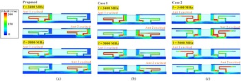
An analysis of the dual-antenna units and their ground plane current distribution was conducted to further look at the interaction between the three types of dual-antenna unit configurations described above. Figure 16 shows the dual-antenna unit and its ground plane current distribution for the dual-antenna operations at 3400 and 5000 MHz. As can be seen from the figure, there was no significant ground plane current present between Ant 1 and Ant 2 for the proposed when Ant 1 was operating at 3400 MHz, but case 1 and case 2 saw a more pronounced ground plane current flowing from Ant 1 to Ant 2 and coupling to excite Ant 2 comparing to the proposed. Therefore, the ECC values of case 1 and case 2 at low frequencies were lower. The same is true when Ant 2 was operated at 3400 MHz. When Ant 1 was operated at 5000 MHz, there was no marked ground plane current presented between Ant 1 and Ant 2 in either the proposed, case 1, or case 2. As a result, all the three dual-antenna configurations are able to reach the ECC values of less than 0.5 at high frequencies, and the same is true when Ant 2 is operated at 5000 MHz.
Ground plane current distribution for antennas operating at 3400 and 5000 MHz and between them for (a) proposed, (b) case 1, and (c) case 2.

Conclusion
A “dual-band MIMO monopole dual-antenna system designed for 5G laptops” was presented in the paper. The 5G MIMO double antenna is simple in structure and requires a profile height of only 2 mm. The size of the 5G double antenna unit is only 29 × 2 × 3 mm3, and both the antennas are identical in structure and size. The antenna structure consists of a fed monopole and a shorted monopole with only 4 mm spacing between the antennas, and it is also configured as a dual-antenna unit in the same direction. Without adopting any isolation element, the dual-antenna system has been simulated and implemented to prove its excellent antenna characteristics with a measured isolation between the two antennas of better than 10 dB and an ECC of less than 0.12. It can cover dual-band operations at 3300–3600 and 4800–5000 MHz in 5G network connections, and its antenna measurement efficiency can reach more than 40%, which is well suited for the applications in narrow-bezel, large-screen mobile communication devices and offers faster transmission speeds.
Acknowledgements
This work was supported by the Ministry of Science and Technology, Taiwan, R.O.C. under grant number MOST 108-2221-E-606-003.
Conflict of interest
None.
 Shu-Chuan Chen obtained B.S. and M.S. in electrical engineering from the Chung Cheng Institute of Technology, National Defense University (CCIT, NDU), Taoyuan, Taiwan, in 1998 and 2004, respectively, and Ph.D. in electrical engineering from National Sun Yat-sen University, Kaohsiung, Taiwan, in 2012. Since 2012, she has been an assistant professor with the Department of Electrical and Electronic Engineering, CCIT, NDU, where she became a professor in 2018. Dr. Chen has published more than 30 refereed journal papers and holds over 20 patents, including USA, Taiwan, and Chinese patents. Dr. Chen is also a member and a chair of the IEEE AP-S Tainan Chapter (2019–2020) of Antenna Engineers of Taiwan (IAET). Her current research interests include internal antennas for mobile communication devices.
 Kuan-Yi Li obtained B.S. and M.S., respectively, in electrical engineering from Minghsin University of Science and Technology, Hsinchu, Taiwan, in 2014, and the National Yunlin University of Science and Technology, Douliu, Taiwan, in 2019. His current research interests include antenna and microwave circuit design.
 Chih-Kuo (Chuck) Lee obtained Ph.D. from the Loughborough University, UK, in 2020. He is currently with the Department of Electrical and Electronic Engineering, Chung Cheng Institute of Technology, National Defense University, Taiwan. His research interests include antennas, wireless communication, and dielectric properties measurements.