


1. INTRODUCTION
For years, Global Navigation Satellite Systems (GNSS) have been applied remarkably successfully for survey, aviation and maritime use where the receiver antenna has a sky view and the satellites are in line of sight. Although satellite navigation is one of the predominant location technologies, it cannot provide satisfactory performance indoors and in dense urban areas, mainly because of significantly lower signal levels and severe multipath environments. However, driven by the Emergency 911 directive in the US, E112 in Europe and blossoming Location Based Services (LBS), position fixes are required in densely-populated urban environments and even indoors, where limited visibility to satellites and severe multipath significantly impact the accuracy and reliability of satellite-based navigation systems. In contrast, wireless location systems based on GSM and CDMA2000 communication systems, including Cell Identity (Cell-ID), Angle of Arrival (AOA) and Time-Difference of Arrival (TDOA) can provide good signal availability. However, they fail to provide satisfactory high-accuracy positioning services since these communication systems are not designed for navigation (Sayed et al., Reference Sayed and Tarighat2005). Recent field studies implementing network-based positioning methods have shown two-dimensional (2-D) position estimation accuracies ranging from 50 to 500 m.
A novel, reliable and accurate terrestrial UWB positioning system with long-range coverage is proposed here for this kind of application. UWB has recently received great attention in academia and industry for positioning applications because of its potential advantages such as high ranging resolution, low transmission power, immunity to multipath, reduced complexity transceiver hardware, low interference to other systems and unlicensed operation in the United States (Zhuang et al., Reference Zhuang, Shen and Bi2003). A UWB signal is characterized by a very wideband radiated spectrum achieved by transmitting a sequence of very short pulses of typical duration of less than one nanosecond. According to the first UWB regulations released by the US Federal Communications Commission (FCC), UWB refers to electromagnetic waveforms with an instantaneous fractional energy bandwidth greater than 0·2 or a bandwidth exceeding 500 MHz (measured at −10 dB points) (FCC, 2002).
The wide bandwidth allows the UWB signal to be received with relatively low material penetration losses. On the other hand, the UWB channel exhibits extremely frequency-selective fading and each received signal contains a large number of resolvable multipath components. The fine time resolution of a UWB pulse with the duration of about 1 nanosecond corresponds to ranging resolution down to about 30 cm, with symbol synchronization (Win and Scholtz, Reference Win and Scholtz1998). The impulse radio UWB signals do not suffer badly from multipath fading, even when pulses overlap. This reduces fade margin in link budgets. In addition, the low power spectral density allows UWB to coexist with narrowband systems without significant interference.
Two major challenges when designing new UWB systems are the selection of appropriate modulation and multiple access schemes. In achieving the required synchronization performance, the modulation scheme has a significant effect on the signal spectral characteristics, transceiver complexity and robustness against interference. On the other hand, to design a UWB positioning system where there is more than one user, multiple access methods must be considered. The two most popular multiple access approaches for UWB systems, Time-Hopping (TH) and Direct-Sequence (DS), are examined in this work. Although these methods have been compared in the past (Somayazulu, Reference Somayazulu2002; Kailas and Gubner, Reference Kailas and Gubner2004; Durisi and Benedetto, Reference Durisi and Benedetto2003), the primary driver for this earlier work has been the multiple access interference (MAI) performance and system capacity. However, for low-density positioning networks, as are considered in this paper, this focus is less important, especially at lower data rates (Roy et al., Reference Roy, Foerster, Somayazulu and Leeper2004). For a long-range UWB system, the modulation scheme needs to be power efficient to achieve greater distance of transmission (FCC, 2002). In this paper we propose an efficient modulation according to the maximum distance of propagation at a given data rate under a maximum probability of error constraint for the UWB point-to-point link considering the spectral analysis of different UWB signals and the link budget. This method can easily evaluate the propagation performance of different modulated signals, without receiver considerations. Moreover, this study addresses the difference between TH and DS systems with respect to ranging performance, which to our knowledge, has not been discussed in previous literature.
2. AIM
The objective of the work reported here is to develop a low-density, low-cost, low-power, terrestrial network for high accuracy urban and indoor navigation. Desired coverage and positioning accuracy are two key performance metrics for positioning systems. This paper determines the proposed modulation and multiple access techniques for this UWB-based positioning system by using the transmitted signal spectral characteristics and synchronization performance as criteria and is organized as follows. Section 3 presents an introduction to UWB radio fundamentals and Section 4 the background information on the proposed UWB positioning system. Section 5 analyses the Power Spectral Density (PSD) of four different UWB signals within the emission mask set by FCC. Section 6 evaluates the ranging quality of these four UWB signals over Additive White Gaussian Noise (AWGN) and multipath channels in terms of probability of correct detection and ranging error for a given signal-to-noise ratio (SNR). Section 7 proposes an optimal modulation and multiple access method for this long-range UWB positioning system.
3. UWB RADIO FUNDAMENTALS
3.1. Pulse shaping
The most popular way of transmitting a UWB signal is by radiating pulses that are very short in time. This communication technique is called Impulse Radio (IR). Several pulse waveforms have been proposed with the consideration that a pulse without a dc offset can be radiated efficiently. The second derivative of a Gaussian function is the most commonly adopted pulse shape for IR UWB (Di Benedetto et al., Reference Di Benedetto and Vojcic2003). In this paper, the fifth derivative of Gaussian pulse is chosen because this pulse can efficiently match the FCC's emission mask and maximize the bandwidth utilisation, as proposed in (Sheng et al., Reference Sheng and Orlik2003). The waveform and the corresponding PSD of a fifth-order derivative are shown in Figure 1.
(Left) Amplitude normalized 5th derivative Gaussian waveform. (Right) PSD of the amplitude tuned 5th derivative of the Gaussian pulse.

3.2. Modulation schemes
Modulation methods for UWB systems can be categorized in two types: time-based techniques and shape-based techniques (Ghavami et al., Reference Ghavami, Michael and Kohno2004). For pulsed UWB systems, the most commonly used modulation techniques include Pulse Position Modulation (PPM), Pulse Amplitude Modulation (PAM) and On-Off Keying (OOK). PPM is a time-based technique; PAM and OOK belong to the shape-based techniques. Because reduced complexity transceiver hardware and low data rate are pursued, only binary signalling methods are investigated in this paper. Figure 2 describes the most popular modulation techniques considered for this UWB system.
• On-Off Keying. On-Off Keying (OOK) signalling is one of the earliest modulation types; bit value 1 is represented by the presence of a pulse, and the absence of a pulse for bit 0.
• Pulse Position Modulation. Pulse Position Modulation (PPM) is the most popular method of modulation in the literature. In a PPM-UWB system, bit value 1 is represented by a pulse with delay relative to the time reference and bit 0 is represented by a pulse without any delay.
• Pulse Amplitude Modulation. For binary pulse amplitude modulation, the information bit is transmitted by modulating the pulse polarity.
• Combined Modulation. Combined modulation schemes such as PAM/M-PPM and PAM/OOK could improve capacity or throughput at the cost of complexity.
Modulation schemes for UWB communication.

3.3. Multiple access schemes
An efficient multiple access scheme is crucial in this proposed UWB system where multiple signals would overlap in time, frequency and space. Time-Hopping (TH) and Direct-Sequence (DS) are the most popular and simple schemes deployed by UWB systems, as shown in Figure 3. In TH-UWB system, each link is assigned a different periodic time hopping code for multiple access, which introduces a time offset on generated pulses. The time hopping code can also reduce the effect of collisions in multiple access schemes and smooth the PSD of transmitted signals (Scholtz, Reference Scholtz1993). DS-UWB systems assign a different spreading code to each user which amplitude modulates basic pulses. Relative performance of TH and DS multiple access has been investigated and analysed in (Somayazulu, Reference Somayazulu2002; Kailas and Gubner, Reference Kailas and Gubner2004 and Durisi and Benedetto, Reference Durisi and Benedetto2003) using measures such as bit-error rate and multi-user capacity. However, they have not been previously compared for synchronisation performance.
TH and DS-UWB-IR signalling structure.

4. OVERVIEW OF UWB POSITIONING SYSTEM
4.1. Key requirements
To meet the needs of “seamless navigation” in the challenging environments mentioned previously, the positioning network must meet the following key requirements:
• decimetre horizontal positioning accuracy will be required (e.g. sometimes it is important to know on which side of a door someone is located). Vertical accuracy depends highly on the transmitter geometry achievable and can be complemented by the use of alternative sensors, such as barometric pressure sensors (Retscher, Reference Retscher2007);
• 95% availability in urban areas and 67% indoors;
• aiming at a low density low cost network, the system is required to support a target maximum link distance of 1000 m in free space between the fixed and mobile terminal;
• capability to host up to 400 mobile terminals per 10 000 m2;
• small size, low power and low cost user terminals.
4.2. System architecture
Key considerations on designing this positioning system are discussed below:
4.2.1. Active Or Passive:
An active system interacts with each user (e.g., a user may be required to “talk” to the system). A passive system broadcasts signals and a user determines his position by simply “listening” to them. Therefore, an active system can service only a limited number of concurrent users. However, a major advantage of an active system is that two way ranging techniques can be introduced to solve the synchronisation problem between master and slave. A passive system on the other hand can accommodate an unlimited number of users, which is extremely desirable, although it requires good timing control at the system level. For the low-density system under development the system-level timing control requirements were deemed to be an acceptable trade off to being able to support an unlimited number of users.
4.2.2. Positioning Method:
Depending on the positioning technique, the angle of arrival (AOA), signal strength (SS), or time delay information can be used to determine the location of a user. The AOA method is not considered suitable for this positioning approach. Use of antenna arrays increases the system cost, annulling one of the main advantages of UWB radio. More importantly, the large number of multipath components of a UWB signal in both indoor and cluttered urban locations can make accurate angle estimation very challenging. For signal strength measurements, the distance estimation quality depends on the channel parameters and the distance between the two terminals (Gezici et al., Reference Gezici, Tian, Giannakis, Kobayashi, Molisch, Poor and Sahinoglu2005). Therefore, this algorithm is very sensitive to the estimation of channel parameter characteristics; the longer the transmission distance the poorer the measurement performance. Time-based approaches can provide very accurate location estimates due to the high time resolution (large bandwidth) of UWB signals. A detailed ranging analysis based on TOA estimation is given in section 6.
4.2.3. Single Band Or Multiband:
The single-band approach uses short UWB pulses and time-domain signal processing to transmit and receive information. This technique benefits from the fact that UWB pulses experience much less Rayleigh fading compared to traditional spread spectrum signals due to the very short chip duration of UWB signals mitigating the wave cancellation effect. Single-pulse architectures offer relatively simple radio designs but provide little flexibility where spectrum management is an objective. Moreover, the main drawback of extremely short time domain pulses is that building wideband front-ends and high-speed ADCs to process signals with several GHz bandwidth is challenging at present due to the high cost and power consumption that would be incurred. However, using a relatively narrower signal bandwidth, for example about 2 GHz (Roberts, Reference Roberts2003), can reduce the complexity of the receiver and the sampling rate of the ADCs significantly. Therefore, the single-band method has been chosen in this system. The multiband UWB approach divides the 7·5 GHz of the RF spectrum available to UWB into multiple smaller bands with bandwidths greater than 500 MHz. This technique has some desirable properties, including the ability to efficiently capture multipath energy with a single RF chain and the flexibility to shape the spectrum easily to alleviate the possible interference concerns. However, multiband UWB systems are criticised for their complexity, which results from using complicated Fast Fourier Transforms (FFTs) (Qiu et al., Reference Qiu, Liu and Shen2005).
4.2.4. Data Rate:
Since this is a pure positioning system, a high data rate is not required. However to calculate the user's position, data on timing and the positions of base stations should be sent to the user. A low data rate transmission will meet this need. More importantly, a low data rate can utilize significantly higher peak powers than those allowable for higher data rate (e.g., communications) systems in order to achieve longer ranges when operating under the FCC's regulations for UWB emissions.
5. POWER SPECTRAL DENSITY OF UWB SIGNALS
Under the FCC regulations, UWB transmit power is strictly limited by an emission mask. Thus to improve the coverage of UWB transmission, a UWB signal with spectrum meeting the emission mask can maximise transmit power within the regulations. The power spectral density is the transmitted power in the signal per unit bandwidth. This spectral characteristic is obtained by computing the Fourier transform of the autocorrelation function (Proakis, Reference Proakis2001), as shown in Equation (1).

where R(τ) is the autocorrelation function of the transmitted signal and Φ(f) is the power spectral density of this signal. In the optimal case for impulse radio, the PSD is determined just by the Fourier transform of a single pulse. As expected, the PSD of a single pulse is continuous, without discrete terms as shown in Figure 1 (Right). Periodic pulse transmission will lead to strong lines in the spectrum of the transmitted signal. The regularity of these energy spikes may interfere with other radio systems over short distances. In order to minimise potential interference from UWB transmissions, time-hopping and direct-sequence techniques can be applied to the transmitted signal, which randomise the pulse train and make the spectrum of the UWB transmission more noise-like. In this section, we include the mathematical description of the PSD of PPM-TH and PAM-DS UWB signals as given in (Di Benedetto and Giancola, Reference Di Benedetto and Giancola2004) and derive the PSD of PAM-TH signals.
The symbols used in the following expressions of UWB signals are:
T s – nominal pulse repetition period (s)
T c – chip time (s)
N s – number of pulses per bit
T b – bit interval (s)
{c j} – TH code with periodicity N p and cardinality N h
{c d} – DS code
{a j} – information sequence to be transmitted after repetition
{b j} – information sequence to be transmitted before repetition
ε – extra delay introduced by PPM (s)
p(t) – pulse waveform
5.1. PPM-TH-UWB case
The PPM-TH-UWB signals can be expressed as:

As common practice, N p is set equal to N s. The PSD of PPM-TH-UWB signal is given by expression below (Di Benedetto and Giancola, Reference Di Benedetto and Giancola2004):

where P v(f) is the Fourier transform of the short pulse train within a single bit, and δ() is the unit-pulse function. This basic multi-pulse is given by:

The Fourier transform of the above signal is given in Equation (5).

P(f) is the pulse spectrum and η is the TH dither. The effect of ε is neglected here, because it is usually much smaller than η. W(f) is the Fourier transform of the probability density function of the transmitted information bits and can be expressed as below:

where p is the probability of a bit having the value 0 and 1-p is the probability of a bit having the value 1. If the source emits symbol 0 and 1 with equal probability, then Equation (6) can be simplified as:

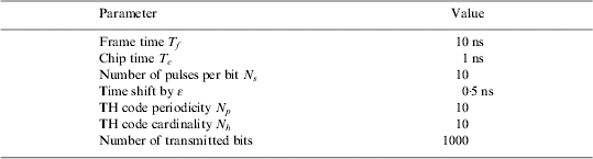
Equation (3) shows that the power spectral density has both continuous and discrete components that depend on the pulse spectrum P(f) and Fourier transform of the probability density function w (Kissick et al., Reference Kissick, Mineta and Rohde2001). The discrete component of the spectrum has lines at 1/T b. The amplitude of these lines is weighted by |W(f)|2. Note that when W(f) is small at multiples of the Pulse Repetition Rate (PRR), the discrete components are small and the continuous component dominates the spectrum. When W(f)→1 in the case of the bit values not changing (p=1) and/or time dither ε being too small, the continuous spectrum disappears and hence the spectral lines dominate. An example of the PSD of a PPM-TH-UWB signal with parameters described in Table 1 is shown in Figure 4 (Left). The presence of spectral lines or spikes lead to a significant power back off to avoid a violation of the FCC regulations and therefore must be suppressed by additional measures. For TH-UWB signals, at a given bit rate, increasing the periodicity and/or cardinality of TH code could help decrease the peaks. Figure 4 (Right) shows the PSD of a PPM-TH-UWB signal with a cardinality of 100 and TH code periodicity of 100. Although discrete components still exist, the PSD of the modified PPM-TH-UWB is more spectrally efficient than the previous one and carries larger average transmitted power. This whitening effect is achieved by distributing power over a larger number of spectrum lines and attenuating spectral peaks (Di Benedetto and Giancola, Reference Di Benedetto and Giancola2004). However increasing the length and/or cardinality of the TH sequence is not a sufficient method to obtain a smooth PSD as shown in Figure 1 (Right).
PSD of a PPM-TH-UWB signal with (Left)Np=10 and Nh=10; and (Right) Np=100 and Nh=100.

Simulation parameters for Figure 4 (Left).
5.2. PAM-TH-UWB case
In the PAM-TH-UWB system, an information sequence composed of ±1 amplitude modulates a TH train of pulses. The generated signal is expressed by:

Consider the same multi-pulse waveform v(t) in Equation (4) for the common case of N p=N s. Equation (8) becomes:

The PSD can easily be derived as follows (Proakis, Reference Proakis2001):

The PSD of PAM-TH-UWB signal is given by:

where σ2 and μ are the variance and mean of the information symbols. It is worth noting that the magnitude of the spectral lines depends on the mean of the information symbols, and that the discrete frequency components vanish when the information symbols have zero mean, μ=0. A PAM-TH-UWB signal with the parameters in Table 1 is generated and shown in Figure 5 (Left). It is shown in Figure 5 (Right) that increasing the TH code period N p and/or the number of chips per frame N h causes an improved power spreading and thus smoothes the spectrum.
PSD of a PAM-TH-UWB signal with (Left) Np=10 and Nh=10 and (Right) Np=100 and Nh=100.

5.3. PAM-DS-UWB case
PAM-DS-UWB signal is defined as follows:

where sequence d is the result of multiplying the information sequence and the DS sequence. Its corresponding PSD is derived in Equation (13):

where R d(m) is the autocorrelation function of sequence d and P c(f) is the code spectrum (Di Benedetto and Giancola, Reference Di Benedetto and Giancola2004). If sequence d is mutually uncorrelated and real, one obtains:

where σ2 and μ are variance and mean of the sequence. When σ2=1 and μ=0, Equation (14) can be simplified as:

The PSD of the signal will be pure continuous components in this case. However the sequence d is not mutually uncorrelated and μ is not zero in most cases, thus many spectral lines will appear in the PSD. An example is given in Figure 6 (Left). The cause of these spectral lines is the sequence d not being mutually uncorrelated, hence we cannot assure μ=0.
(Left) PSD of a PAM-DS-UWB signal, with Ts=2 ns, Ns=10 and Np=5000. (Right) PSD of a PPM-DS-UWB signal.

5.4. PPM-DS-UWB case
Signals of PPM-DS can be expressed by:

Figure 6 (Right) shows the PSD of a PPM-DS-UWB signal. It is not very difficult to understand the poor performance of PPM-DS, because its signal is very similar to an equally spaced pulse train; the time dithering introduced by PPM is much smaller than that of PPM-TH. Hence PPM is not a spectrally efficient modulation type for the DS-UWB signal.
5.5. Link distance analysis
Analysing the PSD is an important part of system design. It affects the choice of modulation and multiple access in terms of spectral efficiency and total transmit power and may impose additional constrains on the total transmit power to comply with the FCC regulations. Table 2 lists the total available transmission power of UWB signals for the modulation schemes considered here. The transmit powers are calculated using the integral of the PSD within a frequency region.

Total allowable transmission power.
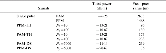
The maximum transmitter-to-receiver link distance, ρ, can be calculated using equation (17). For the analysis here a data rate of 1 kbps under a fixed probability of symbol error of 10−3 has been chosen in order to provide the necessary navigation data content to the users. The following system parameters are assumed: the antenna gains, at the transmitter G T and receiver G R ends are 0 dB; the link margin M s is 5 dB; the noise figure F is 7 dB; k is the Boltzmann constant and standard temperature T 0 is 300 K; the receiver bandwidth is set to the −3 dB-bandwidth of the pulse. The required E b/N 0 for this symbol error rate with PPM and PAM signalling is 9·9 dB and 7 dB, respectively (Sklar, Reference Sklar1998).
According to Figures 4 and 5, and Table 2, the PPM-TH signal and PAM-TH signal with equal parameters have the same PSD and transmit power. This means that in TH system, the PSD of signals are predominantly determined by the characteristics of the TH code. However, based on Figure 6 and Table 2, PAM is more spectrally efficient than PPM for DS-UWB signals. It can also be seen from Table 2 that PAM significantly outperforms PPM in the case of transmitting the same power because PAM is more power efficient than PPM. In other words, PAM provides a better error performance at a given signal-to-noise ratio.
6. RANGING PERFORMANCE
Since multipath is one of the key problems in urban and indoor navigation, ranging performance in such harsh environments becomes another criterion for the selection of modulation and multiple access methods. This section starts deriving the fundamental limits for TOA estimation by using the Cramér-Rao Lower Bound (CRLB). The rest of this section evaluates the single-signal ranging performance of different UWB signals in a multipath-rich channel with Additive White Gaussian Noise (AWGN). The IEEE UWB indoor multipath channel model originally based on the channel model by Saleh and Valenzuela (S-V model) has been chosen for the simulation (Molisch et al., Reference Molisch, Foerster and Pendergrass2003).
6.1. Theoretical range analysis of TOA estimation
The Cramér-Rao Lower Bound indicates the theoretical limits of TOA estimation (Urkowitz, Reference Urkowitz1983):

where  is the variance of TOA estimates, βf is the bandwidth of the received signal, and SNR refers in this case to the signal-to-noise ratio per bit, that is, E b/N 0. The standard deviation of the ranging error can be obtained as the product (c⋅
 ), where c is the speed of light. As indicated in Equation (18), the squared impact of the signal bandwidth to the CRLB makes UWB an outstanding candidate for accurate positioning applications. Figure 7 shows the CRLBs of the ranging error in terms of SNR for three UWB signals with different bandwidths. This figure indicates that even at moderate-to-low SNR region, UWB signals with a minimum bandwidth of 500 MHz can still obtain precise ranging information.
Lower bound of ranging errors.

6.2. Multipath channel model
According to the S-V model for indoor environments, multipath contributions generated by the same pulse arrive at the receiver grouped into clusters. The times of arrival of both clusters and the multipath contributions are modelled as a Poisson arrival process with some mean arrival rate (Di Benedetto and Giancola, Reference Di Benedetto and Giancola2004).
The channel impulse response of the IEEE model can be expressed as follows (Molisch et al., Reference Molisch, Foerster and Pendergrass2003):

where X is a log-normal random variable describing the amplitude gain of the channel, N is the number of observed clusters, K(n) is the number of rays received within the n-th cluster, a nk is the coefficient of the k-th ray of the n-th cluster, T n is the time of arrival of the n-th cluster, and τnk is the delay of the k-th ray within the n-th cluster. An example of the discrete time channel impulse response of the IEEE 802.15.3a channel model 1 is shown in Figure 8.
Discrete time channel impulse response of channel model 1.

6.3. UWB ranging system model
Accurate range estimation is achieved by acquiring accurate time-of-arrival (TOA) measurement. The estimation of TOA is based on timing synchronisation between transmitter and receiver. In this work, a matched-filter receiver has been chosen to achieve temporal synchronisation between transmitter and receiver by detecting the strongest signal.
The UWB positioning system proposed here is modelled in three parts: UWB transmitter, radio channel, UWB receiver. The transmitter generates a pilot sequence of pulses for receiver synchronization. A propagation delay is applied to this pulse train. The propagation of the transmitted signal over the multipath channel is simulated by convolving the delayed pilot sequence and the channel impulse response. The white Gaussian noise is then added onto the signal. The fundamental operation at the receiver is correlation. The incoming signal is circularly shifted and correlated with the template waveform. For simplicity, the Maximum Selection Criterion (MSC) is applied for assessing correlation values, testing all code offsets and then picking the offset with the peak correlation value. Multiplying the delay by the propagation speed of light produces the distance between the transmitting and receiving antennas.
6.4. Simulations
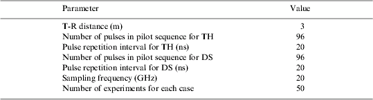
The default simulation parameters are given in Table 3. The synchronisation scheme is based on the presence of a fixed synchronisation preamble at the beginning of each packet (Di Benedetto and Giancola, Reference Di Benedetto and Giancola2004). Obviously, synchronisation performance depends highly on the preamble (Di Benedetto et al., Reference Di Benedetto, Nardis, Junk and Giancola2005). The length of the preamble determines the processing gain, whilst the nature of the preamble determines its correlation properties. Both properties can be chosen in order to provide a desired level of ranging performance. It should be noted, however, that whilst increasing the length of synchronisation sequence will reduce the noise power, it would also increase the acquisition time of the system. Therefore, there are important trade-offs that need to be made when designing the system to meet a particular set of requirements. As stated in (Di Benedetto et al., Reference Di Benedetto, Nardis, Junk and Giancola2005), the length of the preamble falls in the range of 40–100 pulses for different applications. In our simulations, the receiver is assumed to be 3 metres away from the transmitter in the same scenario of the IEEE multipath channel model 1, synchronizing a preamble of 96 fifth derivative of the Gaussian pulses with the same power and the pulse duration of 0·5 ns in both TH and DS systems. The preamble length is the maximum multiple of the bit period in the range above, which is 16 pulses per bit in both cases.
Simulation parameters.
The aim of the simulations is to evaluate the performance of the different signal formats as a function of the signal-to-noise ratio at the receiver. In particular the following key parameters were determined; probability of detection in AWGN and multipath, and ranging error in multipath vs. E x/N 0, where E x is the energy received within a single pulse. Thermal noise is introduced by measuring the energy of the received signal, that is E x, and then generating a noise signal with the corresponding N 0. In this case, channel gain does not affect receiver performance.
Figure 9 (Left) shows the acquisition performance of four signal types under AWGN as E x/N 0 changes from −15 dB to 5 dB, corresponding to the scenario that the receiver is located about 5 metres away from the transmitter in a typical modern office building (Win and Scholtz, Reference Win and Scholtz1998). An increase of E x/N 0 from −15 dB to −7·5 dB results in significantly improved probability of detection of all signals. PPM-DS and PAM-DS have very similar performance and outperform TH systems at the low SNR region.
Probability of correct detection vs. Ex/N0 in AWGN (Left) and vs. Ex/N0 in multipath (Right).

Figure 9 (Right) shows the probability of correct detection of four signals in a multipath environment. In this experiment, the channel model CM1, described in (Molisch et al., Reference Molisch, Foerster and Pendergrass2003) has been used for the underlying multipath channel. A 15 ns maximum delay spread is assumed, which indicates the largest delay due to multipath environments and corresponds to 3 times the root mean square delay (99% confidence interval) for this channel. As shown DS systems still achieve better acquisition performance than TH systems in the low E x/N 0 area ranging from −15 dB to −2·5 dB. Compared to the case of AWGN, the detection probability degrades significantly in the multipath environment due to the introduced inter-symbol interference. Increasing the pulse repetition interval (PRI) is an effective method of mitigating this interference.
Figure 10 shows the ranging accuracy of four signals over a multipath channel. The pulse repetition interval is set to 20 ns for all systems. For both TH and DS systems, higher E x/N 0 does not improve the ranging performance due to inter-symbol interference (ISI) and intra-symbol interference. As expected, the ranging error of TH systems is similar to that of DS system in that all receivers suffer from the same level inter-symbol interference. Because in this multipath environment the first arriving path may not always be the strongest path due to the attenuation caused by the shortly delayed paths (less than one pulse duration), if the receiver synchronises with the strongest signal component for the purpose of range estimation, a large error will occur. This miscorrelation is called intra-symbol interference, which causes an error floor even for high E x/N 0 in Figure 10.
Ranging performance in multipath.

7. CONCLUSIONS AND FUTURE WORK
The target of this work is to design a low-density, high-accuracy terrestrial positioning system for urban and indoor navigation. UWB radios have the significant advantages of simplicity and fine time resolution. To derive the desired UWB ranging signal, we analysed the power spectral density of four kinds of UWB signals in order to maximise the system coverage and investigated their acquisition and ranging performance under AWGN and multipath environments. Our proposed method is based on estimation of TOA for the strongest multipath components.
For a longer-range UWB system to transmit maximum power within the FCC regulations, a UWB signal with a smooth PSD is preferred. The spectra of the most commonly used TH or DS UWB pulse-trains contain strong spectral lines at multiples of the pulse repetition frequency. Increasing the randomness of the position in time or the polarity of the generated pulses, using data modulation, can spread the energy spikes, leading to a smoother spectrum. The spectrum of PPM-TH, PAM-TH and PAM-DS signals can be improved in this way.
Based on the total available transmission power of UWB signals, a maximum transmitter-receiver link distance is calculated for different cases. In TH systems, PAM is more desirable than PPM since binary PAM signals can propagate longer distance by about 83% than binary PPM signal with the same power because of better power efficiency. On the other hand, PAM is more spectrally efficient than PPM for DS-UWB systems, and provides the longest range for all types of signals. Moreover, in detection probability simulations, DS systems outperform TH systems in both AWGN and multipath environments. Therefore, the PAM-DS signal is chosen as the candidate ranging radio in our new positioning network.
However, TH-UWB is potentially more robust to both the near-far effect (Somayazulu, Reference Somayazulu2002) and multiple access interference in a synchronous system. To overcome these two problems in DS systems, the spreading code used in the acquisition sequence has been specifically designed in our other paper (Yu et al., Reference Yu, Brodin, Cooper, Walsh and Strangeways2006). Finally, the simulation of ranging errors demonstrates that the MSC is not a desirable method applied to a receiver working in low SNR and multipath-rich environments, where the first arriving path at the receiver is not always the dominant path even when the receiver is in Line-Of-Sight (LOS) with the transmitter. Ranging based on the TOA of the first arriving signal component will also be investigated in the future of the current project.



