I. INTRODUCTION
High-strength low-alloy (HSLA) steels are of significant importance due to their excellent combined strength and toughness that enables them to be widely used in the transportation, infrastructure, and defense industries. Reference Czyryca, Link, Wong, Aylor, Montem and Gudas1–Reference Wilson, Hamburg, Colvin, Thompson and Krauss3 The steels are usually thermomechanical processed or quench-temper (QT) treated to obtain aimed mechanical properties. During QT treatment, the strength, in addition to arising from (tempered) dislocated lath martensitic structure, is mainly resulted from the precipitation hardening of highly dispersed nanoscale Cu-rich precipitates (CRPs) formed during the tempering process. Reference Miglin, Hirth, Rosenfield and Clark4 However, strength and toughness always have an inverse relationship. Reference Ritchie5 The nanoscale CRPs that contribute to the maximum strength are also often responsible for the degradation of toughness, although the coherent, coplanar Cu-rich clusters/precipitates that act as ‘misfit centers’ are possibly beneficial to toughness by improving the mobility of dislocations. Reference Fine, Vaynman, Isheim, Chung, Bhat and Hahin6 Hence, efforts have been made to introduce reverted austenite (RA) into the steels via intercritical heat treatment (IHT) (or partial austenite reversion treatment exactly) to mitigate the detrimental effect of the small CRPs on toughness. Previous studies Reference Ahn, Kim, Byun, Oh, Kim and Hong7–Reference Liu, Wen, Zhang, Gu, Li and Lavernia9 have manifested that the RA exhibits a positive effect on toughness improvement and strength ratio (yield strength/tensile strength) reduction, with a precondition that the RA is thermally and mechanically stable at ambient temperature. Reference Fultz, Kim, Kim, Kim, Fior and Morris10 However, the IHT simultaneously attenuates the precipitation hardening effect due to the coarsening of CRPs at the elevated temperature when stable RA is readily formed, but the large CRPs with the low number density show a faint detrimental effect on toughness. Reference Liu, Wen, Zhang, Gu, Li and Lavernia9 On the other hand, the carbide-forming elements Mo, Cr, and Nb may lead to the formation of alloyed carbide during IHT, although the alloyed carbide is impossible to be widespreadly formed like CRPs because of the relatively low carbon content (∼0.05 wt% in nominal composition for the present steel). Reference Wilson, Hamburg, Colvin, Thompson and Krauss3 It is proven that the coarsened large-size carbides with a long interparticle distance can efficiently improve the toughness of a reactor pressure vessel (RPV) steel with ∼0.21 wt% C after IHT. Reference Ahn, Kim, Byun, Oh, Kim and Hong7 Accordingly, to attain optimal strength and toughness balance, it is essential to tailor the distributional morphology of CRPs, RA, and alloyed carbide based on their separate precipitation characteristics.
Cu precipitation in the ferritic matrix has been comprehensively investigated in the aspect of crystallographic, compositional, and morphologic evolution of CRPs during thermal aging. Reference Othen, Jenkins, Smith and Phythian11,Reference Kolli and Seidman12 We emphasize here that the CRPs are inherently rich in Ni and Mn as well as a high amount of Fe at the early nucleation stage, and Ni and Mn tend to segregate at the CRP/matrix heterophase interface to form the core–shell structure. Reference Kolli, Mao, Seidman and Keane13 From this viewpoint, it is seen that Cu precipitation is greatly in association with the diffusion and partitioning of Ni, Mn, and certainly Cu. The partial austenite reversion during IHT preferentially occurs by a diffusional mechanism in most low-alloyed steels, because solute diffusion in the lean steels is easier compared to that for high Ni or Mn martensitic steels. Reference Nakada, Tsuchiyama, Takaki, Ponge and Raabe14 It is known that the nucleation of RA is initiated by C segregation or clustering, and the early stage of growth of RA is controlled fast diffusion of C. Reference Wei, Enomoto, Hadian, Zurob and Purdy15 The growth of RA to the final equilibrium state proceeds at a relative slow rate, because the growth process requires continuous diffusion and partitioning of substitutional austenite stabilizing elements Ni, Mn, and Cu. Meanwhile, the precipitation of iron-carbide is also started with the diffusion and segregation of C which leads to the formation of nanoscale C clusters even at room temperature, Reference Miller, Beaven and Smith16 whereas the formation of alloyed carbide occurs at expend of the pre-existing of iron-carbide or C clusters. Reference Thomson and Miller17 Furthermore, stronger carbide-forming elements Mo, Cr, Nb, etc., will replace the weaker ones Fe and Mn with the proceeding of carbide precipitation. Reference Janovec, Vyrostkova and Svoboda18
Considering the above-mentioned possible diffusion or partitioning behavior of related atoms during the formation of CRPs, RA, and alloyed carbide, it is anticipated as follows: (i) Ni, Mn, and Cu can participate in Cu precipitation to form CRPs and meanwhile condense into RA contributing to its continuous growth; (ii) the preformed C cluster or C segregation zone can transform into alloyed carbides by absorbing carbide-forming elements Mo, Cr, Nb, etc., or alternatively assist austenite reversion by attracting and condensing austenite stabilizing elements Ni and Mn; and (iii) there is a possibility that the competitive precipitation of CRPs with RA and the coprecipitation of CRPs with alloyed carbide occur simultaneously during IHT for alloyed steels. Reference Wang, Sha, Shen and Liu19–Reference Zhang, Liu, Miller, Wang, Wen, Fujita, Hirata, Chen, Chen and Chin22 Meanwhile, the hierarchical lath martensitic structure provides abundant nucleation sites for CRPs, RA, and alloyed carbide and fast diffusion pathways for solute atoms, which makes the precipitation reactions easier.
In this paper, the interactive formation of CRPs, RA, and alloyed carbide is investigated by electron back scatter diffraction (EBSD), transmission electron microscopy (TEM), and atom probe tomography (APT), concerning the solute segregation and partitioning behavior between these three different precipitate features. The knowledge on the roles of an alloy element in the interactive precipitation reaction will help to tailor the precipitate size, morphology, and number density via optimizing the chemical composition and heat treatment schedule for desired high strength without significant degrading toughness.
II. EXPERIMENTAL
The material used is a typical HSLA steel with the nominal composition of 0.04 C, 0.25 Si, 0.89 Mn, 1.54 Cu, 3.51 Ni, 0.59 Mo, 0.49 Cr, 0.050 Nb, 0.033 Al, 0.003 N, 0.008 P, and 0.005 S (in wt%). After homogenization and forging, the ingot was hot-rolled at 1100 °C with totally 9 pass into plate shape with a thickness reduction from 140 to 32 mm followed by air cooling. The heat treatment consists of an austenitization/solutionization step at 900 °C for 0.5 h followed by water-quenching (Q), an intercritical tempering (partial austenite reversion) step at 675 °C for 1 h followed by water-quenching (I), and a conventional tempering step at 500 °C for 1 h followed by air-cooling (T). The additional low-temperature tempering at 500 °C mainly aims to promote the precipitation of nanoscale CRPs apart from the relatively large-size CRPs formed at 675 °C.
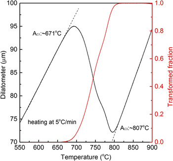
The start temperature of austenite reversion was determined to be approximately 671 °C by dilatometry test (TA-DIL 805, TA Instruments, Asse, Belgium) on the as-quenched sample, as shown by the dilatational curve (black) and austenite transformed fraction curve (red) calculated by the lever rule in Fig. 1. It is seen that intercritical tempering at 675 °C for partial austenite reversion can create stable RA, although the RA just possesses a small volume fraction. It is also reasonable to establish the austenitization temperature to be 900 °C for obtaining martensitic structure after water-quenching, as the ferrite–austenite transformation is entirely finished at approximately 807 °C.
Dilatational curve (black) and austenite transformed fraction curve (red) showing the start and finish temperatures of austenite reversion.

EBSD characterization was conducted with a step size of 0.1 µm on a field-emission scanning electron microscope (NOVA NanoSEM 230, FEI, Hillsboro, Oregon) at 20 kV to give the general microstructure of lathlike martensitic structure and possible RA’s morphology. TEM observation was conducted using a JSM-2010F (JEOL Ltd., Tokyo, Japan) at 200 kV to show the detail morphology of CRPs and RA. Thin foils for TEM specimen were prepared by mechanical grinding to 50 μm thick followed by electropolishing in a mixture of 90 vol% alcohol and 10 vol% perchloric acid using a Struers TenuPol-5 double jet electropolisher (Roper Technologies Inc., Sarasota, Florida) at a voltage of 30 V at −30 °C. APT analysis was performed utilizing a local electrode atom probe (LEAP™ 3000 HR, CAMECA, Gennevilliers, France) for the thorough analysis of the interaction of CRPs, RA, and alloyed carbide at atomic scale. APT data collection was executed with a residual pressure of 3 × 10⁻⁹ Pa, a specimen temperature of −223 °C, a pulse repetition frequency of 200 kHz, and a pulse-voltage to dc-voltage ratio of 15%. Atom probe specimen tips were prepared employing a standard two-stage electropolishing method at room temperature. Reference Miller23 Data analysis was performed using the IVAS 3.6.2 software.
III. RESULTS
A. EBSD observation
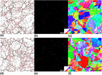
Figure 2 shows EBSD microstructure obtained with a step size of 0.1 µm for the (a–c) QI and (d–f) QIT samples (Q, I, and T denote different heat treatment steps in Section II). A typical lathlike martensitic structure is obviously seen with martensite packets and blocks within prior austenite grains after intercritical tempering at 675 °C [Fig. 2(a)]. A dispersion of small face-centered cubic (fcc) structured RA is detected evenly distributed within the body-centered cubic (bcc) structured tempered martensitic matrix, as shown by the orientation imaging maps in Figs. 2(b) and 2(c). The comparison between Figs. 2(a) and 2(b) reveal that the RA is generally formed in association with the martensite packet and block boundaries as well as prior austenite grain boundaries (PAGBs) that are outlined by black lines with misorientation between 15° and 45°. The RA almost has a common crystallographic orientation within one prior austenite grain or martensite packet, which agrees with the observation in a previous study for high Cr and Ni martensitic steel. Reference Nakada, Tsuchiyama, Takaki and Hashizume24 The microstructure for the QIT sample is similar to that for the QI sample, as the lathlike structure has reached a relatively equilibrium state after intercritical tempering at 675 °C and cannot be substantially changed by subsequent tempering at comparatively lower temperature of 500 °C, as shown Figs. 2(d) and 2(f). In addition, the distributional morphology of RA in the QIT sample is also consistent with that observed in the QI sample. Previous study showed that the volume fractions of RA in the QI and QIT samples are approximately 11% and 10%, respectively. Reference Liu, Wen, Zhang, Gu, Li and Lavernia9 It seems that the RA is sufficiently stable and does not essentially decompose upon tempering at 500 °C.
EBSD micrographs showing the microstructure of the QI (upper row) and QIT (lower row) samples. (a and d) Grain boundary map with coloring criterion of boundary: 5° ≤ θ < 15°, gray lines; 15° ≤ θ < 45°, black lines; and θ ≥ 45°, red lines. Crystal orientation imaging maps for (b and e) fcc RA and (c and f) bcc ferritic matrix, colors of different crystals showing the crystallographic orientations as indicated in the stereographic triangle. Step size: 0.1 μm. Q: quenched in water from 900 °C, I: intercritical tempering at 675 °C, T: tempering at 500 °C. All micrographs are with the same magnification with the scale bar marked in (f).

B. TEM characterization
Figure 3 displays TEM micrographs of the (a) QI and (b) QIT samples, showing some microstructural differences unrevealed by the EBSD observation. First, the dislocation density is substantially reduced, and the martensite laths become broader and the LBs become undistinguishable after additional tempering at 500 °C. Second, the small RAs, especially those are filmlike, are detectable by TEM. The RA is mainly located at the LBs or at the conjunctions of the martensite packet and block. The general distributional morphology varies little after tempering at 500 °C, except that some RA neighbored with secondary fresh martensite (M/A islands) is more distinctly imaged in TEM due to the tempering. In addition, highly dispersed fine precipitates are observed in both QI and QIT samples. In general, the RA and the precipitate are comparable in size and in volume fraction or number density independent of the tempering. It is further confirmed that the tempering does not significantly change the microstructure developed in QI treatment.
Bright-field TEM micrographs of the (a) QI and (b) QIT samples, showing the distributional morphology of RA and CRPs. RA: reverted austenite. Q: quenched in water from 900 °C, I: intercritical tempering at 675 °C, T: tempering at 500 °C.

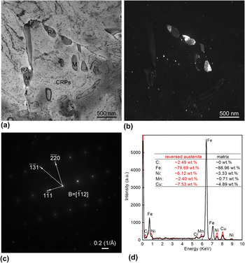
We further address the nature of RA and CRPs as well as their interaction based on the detail TEM analysis of the QIT sample, as shown in Fig. 4. The microstructure is free of dislocation due to sufficient double-step tempering at 675 and 500 °C, and several blocky RA crystals are clearly observed located at PAGBs and in grain interior, as shown by Fig. 4(a). The RA is simultaneously illuminated in the corresponding dark-field image [Fig. 4(b)] generated with (−112)γ-Fe(FCC) reflection [as indicated by the electron diffraction pattern in Fig. 4(c)], which corroborates that the RA in a given grain has nearly common crystallographic orientation. In addition, the RA seemingly grows in a selective direction after nucleation at PAGBs, which is consistent with the known variant restriction mechanism for austenite reversion. Reference Watanabe and Kunitake25 The qualitative EDS analysis in Fig. 3(d) presents the compositional difference between the RA (red) and the ferritic matrix (black), that is, the RA is evidently rich in the austenite stabilizers C, Ni, and Mn as well as Cu. The solute enrichment increases the stability of RA and makes it more possible to retain to the ambient temperature. However, part of some RA crystals transform into secondary fresh martensite upon water-cooling, especially for those in grain interior. It seems that the RA formed in grain interior processes lower stability because of slower solute diffusion compared to that on PAGBs, which is also consistent with the EBSD observation that the stable blocky RA is generally arranged around PAGBs, as shown in Fig. 2(e). The newly formed martensite, which exhibits darker contrast, forms an adjacent structure with the untransformed RA. It is anticipated that the austenite stabilizing elements are heterogeneously distributed throughout the RA. The earlier formed RA has a higher stability because the solute diffusion is more sufficient from the beginning of nucleation. Furthermore, considering the adjacent structure of RA and the secondary fresh martensite, it is established that the RA/ferrite boundary shifts in a certain direction other than in the whole circumferential direction of the nuclei of RA.
(a) Bright-field and (b) centered-dark-field TEM micrographs, (c) electron diffraction pattern with its index, and (d) EDS analysis of the QIT sample, revealing the RA located at the PAGBs. RA: reverted austenite, M: martensite, CRPs: Cu-rich precipitates. Q: quenched in water from 900 °C, I: intercritical tempering at 675 °C, T: tempering at 500 °C.

High number density CRPs are observed uniformly distributed in the ferritic matrix and at the PAGBs. These CRPs are thought to be formed directly from the solid solution during intercritical tempering at 675 °C (Fig. 3), because the CRPs formed at 500 °C tempering are extremely small and hardly detected by conversional TEM observation. Reference Liu and Zhao26 It should be noted that the CRPs at PAGBs are roughly comparable in size to those in grain interior, which means the crystallographic defects such as PAGBs can act as nucleation sites for CRPs whereas cannot contribute to their rapid growth or coarsening. The CRPs are also detected in the secondary fresh martensite. Since the fast cooling following intercritical tempering prohibits any diffusive transformation, the CRPs in the fresh martensite are therefore thought to be formed during conventional tempering at 500 °C. The CRPs have not undergone excessive growth due to the relatively lower temperature and thus have comparatively smaller sizes than those in the ferritic matrix and at PAGBs. On the other hand, the fresh martensite originated from the RA is also rich in Ni, Mn, and Cu, although the actual amount of these austenite stabilizing elements are slightly lower in content than in stable RA. The high solute concentration in the fresh martensite will promote Cu precipitation, resulting in the relatively higher number density of CRPs within. In contrast, there are no CRPs in RA. The solid solubility of Cu in austenite is much higher than in ferrite, which undoubtedly prohibits the Cu precipitation in RA during conventional tempering. Moreover, there is seemingly no possibility that Cu precipitation occurs in RA during austenite reversion. Although, Cu precipitation can occur by the interphase precipitation during the continuous cooling transformation of austenite, Reference Thompson and Krauss27–Reference Liu, Li, Gu and Liu30 Cu precipitation is probably ceased because the Cu concentration at the mobile austenite/ferrite boundary during austenite reversion is too low to form CRPs’ nuclei. Instead, Cu atoms are more readily diffused into the neighbored RA and contribute to its growth. In other words, the Cu diffusion rate surpasses the migration of the RA/ferrite boundary during austenite reversion at 675 °C, and the Cu atoms preferentially diffuse into RA’s nuclei other than condensing to the mobile RA/ferrite boundary to contribute to Cu precipitation therein. Consequently, few CRPs are observed in and around the RA, which conforms the competitive formation of CRPs and RA during austenite reversion.
C. APT analysis
Figure 5 gives the APT analysis of the QI sample as supplementary data for EBSD and TEM observations to demonstrate the buried structural features at the atomic scale. The 3D reconstructed atom maps of C, Si, Ni, Mn, Cu, Cr, Mo, and Nb are shown in Fig. 5(a). C atoms are not homogenously distributed, as C segregation can occur at crystallographic defects such as dislocations to form nanoscale C-rich clusters even at room temperature. The C-rich clusters represent the very early stage of carbide formation because no distinct segregation of strong carbide-forming elements Mo, Nb, etc., is obviously seen at the same spatial position. In contrast, a C-rich zone at the bottom of C map is evidently observed, indicating the formation of alloyed carbide since where is also significantly rich in Mo and Nb. The presence of the Cu-rich zones in Cu map indicates the formation of CRPs. The Mn enrichment at CRPs’ positions is mainly induced by the segregation and condensation of Mn at the CRPs/matrix heterophase interface and in the CRPs’ interior. Reference Gorbatov, Gornostyrev, Korzhavyi and Ruban31 Si, Ni, and Cr seemingly exhibit no evident segregation or enrichment at the C-rich or Cu-rich regions based on their separate atom maps, although these elements are also in association with the formation of CRPs or alloyed carbide. Figure 5(b) shows the C-rich clusters or carbide and CRPs delineated by 0.5 at.% C and 10 at.% Cu isoconcentration surfaces, respectively. It is evident that the linear arrangement of C-rich clusters correlates to the straight martensite LB, which is consistent with the previous observation in a QT treated HSLA steel with lower Ni and Cu contents. Reference Liu and Zhao26 The C segregation would assist the nucleation of alloy carbide and RA at the crystallographic defects. In addition, the alloyed carbide at the bottom of the reconstruction map is found to coprecipitate with one of CRPs. Only two CRPs are found in several tens of nanometer region. The CRPs are comparable in size to those observed by TEM, as shown in Fig. 3.
APT results of the QI sample. (a) 3D reconstruction atom maps of C, Si, Ni, Mn, Cu, Cr, Mo, and Nb. (b) C-rich clusters/alloyed carbide and CRP delineated by 0.5 at.% C and 10 at.% Cu isoconcentration surfaces, respectively. (c and d) 1D composition profiles across a CRP (ROI-1) and an alloyed carbide (ROI-2) along the height (Z-axis) of the selected cylinders in (b), respectively. ROI: region of interest. Q: quenched in water from 900 °C, I: intercritical tempering at 675 °C.

The one-dimensional composition profile of a selected CRP [region of interest (ROI)-1 in Fig. 5(b)] is shown in Fig. 5(c). Cu concentration is as high as ∼90 at.% in the precipitate interior, indicating that the CRP reaches its stable stoichiometric composition and thus is considered to be at its later precipitation stage, as CRPs at early nucleation stage often contain a considerable high amount of Fe as well as some Ni and Mn. Reference Isheim, Gagliano, Fine and Seidman32,Reference Schober, Eidenberger, Leitner, Staron, Reith and Podloucky33 The concentrations of both Ni and Mn in the CRP interior are approximately 3 at.%. Taking the nominal composition of Ni (∼3.5 Ni wt%) and Mn (∼0.8 wt%) into account, it seems that Ni appears to segregate at the precipitate/matrix heterophase interface, whereas Mn is more ready to stay in the precipitate interior without evident segregation at the interface, at least for the present coarsened CRPs. It is suggested that, compared with Ni, Mn exhibits a weak tendency to segregate to the interface, which is consistent with a computation simulation study. Reference Gorbatov, Gornostyrev, Korzhavyi and Ruban31 Al and Si show no distinct partitioning between CRPs and matrix, although these elements also greatly correlate with the Cu precipitation in ferritic steels with higher Al and Si. Reference Kolli and Seidman12,Reference Kolli, Mao, Seidman and Keane13 Moreover, the CRP contains negligible amounts of C and the carbide forming elements Cr, Mo, Nb as well as P. These elements do not participate in Cu precipitation and would be expelled into the surrounding matrix, which makes the formation of alloyed carbide in the periphery of CRPs possible, i.e., coprecipitation, as shown in Fig. 5(b). One-dimensional composition profile of the alloyed carbide in ROI-2 [Fig. 5(b)] is given in Fig. 5(d). The alloyed carbide contains approximately 50 at.% C and a considerable high amount of strong carbide-forming elements Mo, Cr, and Nb. The compositions corroborate the precipitate to be an alloyed carbide. However, Ni, which is not a carbide-forming element but a recognized austenite stabilizer, is also significantly enriched in the carbide with a concentration of as high as ∼30 at.%. From this viewpoint, it is not a typical alloyed carbide. But the precipitate also cannot be RA because austenite contains much less C. Moreover, the precipitate is not evidently rich in Mn which is an austenite forming element. In the present situation, Mn seemingly acts as a weak carbide-forming element like Fe and is replaced by strong carbide formers Mo and Nb during carbide precipitation, Reference Liu, Liu and Zhao34 testifying the precipitate to be an alloyed carbide. In contrast, the noncarbide-forming elements Al, Cu, Si, and P slightly partition to the precipitate, demonstrating the precipitate to be RA. In other words, the compositions of the alloyed carbide are inconsistent with the previous experimental and calculation results. Reference Ande and Sluiter35 Therefore, this is a unique carbide precipitate different from the typical alloyed carbides.
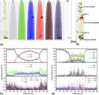
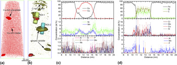
Figure 6 gives the APT analysis of the QIT sample, showing the APT reconstructed Cu map [Fig. 6(a)] and the 3D distribution of C-rich clusters or alloyed carbide and CRPs [Fig. 6(b)]. The atomic-scale structure is also not changed by the additional tempering treatment, since the general distributional morphology of the structural features is consistent with that observed in the QI sample [see Fig. 5(b)]. Additionally, the composition profiles across the selected CRP in ROI-1 and the alloyed carbide in ROI-2 [Fig. 6(b)] exhibit similar distribution characteristics of the related atoms, as shown in Figs. 6(c) and 6(d), respectively. However, three differences are worth mentioning. First, in addition to the large-size CRPs (formed during austenite reversion treatment), nanoscale Cu-rich clusters are also detected by APT, as shown in Fig. 6(a). The small Cu-rich clusters, which are not found in QT sample, are thought to be formed during the additional tempering at 500 °C since there are also adequate Cu atoms available in solution after QI treatments [see Cu map in Fig. 5(a)]. Second, two different Cu concentration peaks in Fig. 6(c) indicate the presence of two adjacent CRPs with different size. The phenomenon well explains the coarsening process of CRPs during which the larger CRP grows at expend of the smaller one due to Ostwald ripening. Additionally, the selected CRP here is smaller than the one in the QI sample, and the Mn segregation at the CRP/matrix heterophase interface is more distinct, as shown in Fig. 6(c). Third, compared to that in the QI sample, the alloyed carbide contains less amount of Mo and Cr and is nearly free of Nb, and Mo is more readily to segregate at the precipitate/matrix interface. In the view of the reduced carbide-forming elements, the alloyed carbide in the QIT sample is seemingly more beyond the equilibrium composition compared to the one coprecipitated with CRP in the QI sample. This is possibly due to the relatively insufficient atom diffusion during the independent formation of the alloyed carbide in the QIT sample, although it undergoes an additional tempering at 500 °C for 1 h. Similarly, the austenite stabilizers Ni and Cu are observed to be significantly enriched in the alloyed carbide interior. However, the concentrations of Ni and Cu are comparatively higher than in the alloyed carbide coprecipitated with CRP. The formation of a CRP neighbored to the alloyed carbide in the QI sample consumes Cu atoms, which accounts for the lower Cu within, as shown in Fig. 5(d). In addition, the coprecipitation of CRPs and alloyed carbide also contributes to the growth of the alloyed carbide into a comparatively larger size in the QI sample. Thus, it can be seen that the coprecipitation of CRPs and alloyed carbide changes the composition and actual size of these two features.
APT results of the QIT sample. (a) 3D reconstruction atom map of Cu. (b) C-rich clusters/alloyed carbide and CRPs, delineated by 0.5 at.% C and 10 at.% Cu isoconcentration surfaces, respectively. (c and d) 1D composition profiles across a CRP (ROI-1) and an alloyed carbide (ROI-2) along the height (Z-axis) of the selected cylinders in (b), respectively. ROI: region of interest. Q: quenched in water from 900 °C, I: intercritical tempering at 675 °C, T: tempering at 500 °C.

IV. DISCUSSION
The austenite stabilizing elements Ni, Mn, and Cu diffuse and condense into the preformed C-rich zones to facilitate RA’s nucleation and growth during austenite reversion, and meanwhile enhance the stability of RA upon cooling. The EDS analysis in Fig. 4(d) of a selected blocky RA crystal also demonstrates that the RA is significantly rich in Ni, Mn, and Cu. On the other hand, Ni can form fine Ni-rich clusters that act as nucleation sites for CRPs during Cu precipitation. Reference Liu, Gu and Liu36,Reference Cerezo, Hirosawa, Rozdilsky and Smith37 Also, Ni and Mn segregate at the CRP/matrix heterophase interface or condense into the CRPs, as shown by the composition profiles across the CRPs in Figs. 5(c) and 6(c). This indicates that Cu precipitation is greatly associated with Ni and Mn clustering or segregation and thus consumes a considerable amount of Ni, Mn, and certainly Cu. Therefore, as both important austenite stabilizing elements and necessary CRPs’ constituents, Ni, Mn, and Cu will competitively participate in austenite reversion and Cu precipitation at the same time. In the present study, it seems that Ni, Mn, and Cu are more prone to participate in austenite reversion other than just contribute to the nucleation and growth of CRPs during austenite reversion. It is also anticipated that the preformed CRPs at RA/matrix boundaries if any would eventually dissolve into the RA, as no CRPs are observed in or around the RA crystals, as shown in Fig. 4.
C clustering or segregation can occur at room temperature especially in hierarchic martensitic structure that provides abundant nucleation sites for alloy carbide and RA. The alloyed carbide, which is not frequently detected by TEM like CRPs in low-carbon HSLA steels, Reference Wilson, Hamburg, Colvin, Thompson and Krauss3,Reference Miglin, Hirth, Rosenfield and Clark4 is expected to be formed together with RA during austenite reversion. Similar to the nucleation of RA, the formation of alloyed carbide is thermodynamically favorable and initiated by the C clustering or segregation. If so, the austenite stabilizing elements Ni, Mn, and Cu and the carbide-forming elements Mo, Cr, and Nb all possibly diffuse into the pre-existing C-rich zones to contribute to the growth of both RA and alloyed carbide at the same time. From this viewpoint, it is easy to understand the unique compositions of the alloyed carbides detected by APT in Figs. 5 and 6, which are concurrently rich in the carbide formers and the austenite stabilizers especially Ni. The compositions are somehow similar to that of RA formed by ‘segregation engineering’ mechanism in high Mn steels. Reference Raabe, Sandlobes, Millan, Ponge, Assadi, Herbig and Choi38 It seems that austenite reversion may occur with intense enrichment of most of the elements in the pre-existing C-rich zones by ‘segregation engineering’ mechanism in present steel. However, different from the common blocky RA crystals observed by TEM in Figs. 3 and 4, the small RA seemingly cannot grow to a large-size and attain its intrinsic composition, because the carbide formers Mo, Cr, Nb, etc., would simultaneously continuously diffuse into the RA interior to form alloyed carbide. The process will significantly prohibit the growth of small RA. If the condensation of C and the strong carbide formers Mo, Cr, and Nb constantly proceeds, the RA nuclei with intense solute enrichment possibly evolve into the observed alloyed carbide but with a considerable high amount of Ni retained. The presence of the alloyed carbide with unusual compositions is, therefore, considered to be a direct evidence of the competitive formation of RA and alloyed carbide during austenite reversion.
In agreement with the previous observation in low-carbon Cu-bearing steels, Reference Wang, Sha, Shen and Liu19–Reference Zhang, Liu, Miller, Wang, Wen, Fujita, Hirata, Chen, Chen and Chin22 the coprecipitated and collocated CRPs with alloyed carbide or C-rich clusters are also detected by APT, as shown in Figs. 5 and 6. Comparison of the composition profiles of the alloyed carbides collocated with CRP in Fig. 5(d) and the one without CRP in Fig. 6(d), it is known that the alloyed carbide formed independently contains higher amount of CRP’s constituent elements Cu and Ni, whereas the one collocated with CRP contains high amount of carbide-forming elements Mo, Cr, and Nb. The formation of CRPs will expel Mo, Cr, and Nb into the adjacent carbide nuclei and accelerate its growth, which leads to higher concentrations of these elements in alloyed carbide. On the other hand, the growth of alloyed carbide tends to deplete Cu and Ni within. It is therefore suggested that these two features provide the solute atoms for each other and facilitate their respective nucleation and growth, which makes the coprecipitation more accessible.
V. CONCLUSION
The possible precipitation reactions in a HSLA steel with austenite reversion treatment at 675 °C for 1 h are experimentally studied by combined EBSD, TEM, and APT at different scales. The microstructure exhibits typical lathlike martensitic morphology, mainly decorated by RA and CRPs. The blocky RA is predominately located at the PAGBs and the CRPs are uniformly dispersed in the ferritic matrix.
There is a strong competition between austenite reversion and Cu precipitation based on the fact that no CRPs are found in and around the blocky RA crystals, since austenite revision necessarily consumes the constituent elements Cu and Ni of CRPs. The possible competitive precipitation of RA and alloyed carbide leads to the formation of nonequilibrium small alloyed carbide detected by APT, which is simultaneously rich in austenite stabilizing elements Ni and Cu and carbide-forming elements Mo, Cr, and Nb. The formation of RA and alloy carbide are both triggered by C segregation or clustering, and most of the elements, especially Ni, competitively tend to condense in the preexisting C-rich zones. Additionally, CRPs and alloyed carbide provide the constituent atoms for each other and facilitate their respective nucleation and growth, which makes the coprecipitation accessible.
ACKNOWLEDGMENT
This work was financially supported by the China Postdoctoral Science Foundation (No. 2013M541517).