1 Introduction
We shall study two-dimensional irrotational periodic waves propagating under the influence of gravity
 $g$
without change of form at the interface between two ideal unbounded fluids of different densities
 $\unicode[STIX]{x1D70C}_{1}$
and
 $\unicode[STIX]{x1D70C}_{2}$
when
 $\unicode[STIX]{x1D70C}_{1}<\unicode[STIX]{x1D70C}_{2}$
and
 $\unicode[STIX]{x1D70C}_{2}$
is the density of the lower fluid. For
 $\unicode[STIX]{x1D70C}_{1}=0$
, these waves are the well-known surface Stokes waves. It was conjectured by Stokes that the surface waves achieve their maximum amplitude when the maximum velocity of the fluid in the
 $x$
-direction equals the phase speed of the wave. Then, in the frame of reference moving with the phase speed, the highest surface waves would have stagnation points at the crests, and from a local analysis of the equations of motion, Stokes showed that the crests would be sharp and enclose an angle of
 $120^{\circ }$
. A rigorous mathematical confirmation of the Stokes conjecture was given by Amick, Fraenkel & Toland (Reference Amick, Fraenkel and Toland1982).
It is clear that for
 $\unicode[STIX]{x1D70C}_{1}>0$
, Stokes’ limiting configuration is no longer possible, because the stagnation angular point in the lower fluid would result in an infinite velocity at the same point but in the upper fluid, and hence satisfying the condition of continuous pressure across the interface becomes impossible.
Let
 $\unicode[STIX]{x1D703}$
be the angle between the tangent line to the interfacial curve and the horizontal direction. Holyer (Reference Holyer1979) proposed that the limiting configurations of interfacial waves are those with a vertical slope of the interface (
 $|\unicode[STIX]{x1D703}|_{max}=\unicode[STIX]{x03C0}/2$
). This conjecture generalizes Stokes’ conjecture, because the vertical slope means that, at the point of the interface where this slope is achieved, the horizontal particle velocity equals the phase speed.
It is evident that, if at a point of the interface
 $|\unicode[STIX]{x1D703}|>\unicode[STIX]{x03C0}/2$
, then at this point the horizontal velocities on both sides of the interface will be greater than the phase speed. Saffman & Yuen (Reference Saffman and Yuen1982) pointed out that there are no dynamical or kinematical reasons to reject interfacial waves for which the horizontal velocity exceeds the phase velocity at some points. Numerical evidence of the existence of such waves was demonstrated by Meiron & Saffman (Reference Meiron and Saffman1983). For these S-shaped waves, some portions of heavier fluid lie above lighter fluid, and Meiron & Saffman (Reference Meiron and Saffman1983) called them ‘overhanging waves’.
Thus, the computations of Meiron & Saffman (Reference Meiron and Saffman1983) showed that the appearance of the vertical slope on the interface does not correspond to a limiting configuration. Saffman & Yuen (Reference Saffman and Yuen1982) proposed that the overhanging S-shaped waves continue to exist until the interface intersects itself. However, the calculations of Meiron & Saffman (Reference Meiron and Saffman1983) were stopped well before any such limiting configurations, and hence do not confirm the conjecture of Saffman & Yuen (Reference Saffman and Yuen1982).
Turner & Vanden-Broeck (Reference Turner and Vanden-Broeck1986) confirmed the existence of overhanging waves as computed by Meiron & Saffman (Reference Meiron and Saffman1983) and extended their calculations. Computing along a continuous branch of solutions, Turner & Vanden-Broeck (Reference Turner and Vanden-Broeck1986) found that there is a return from the overhanging configuration to one in which the interface is a single-valued function of the horizontal variable. The authors conjectured that an alternation between non-overhanging and overhanging waves continues indefinitely as one proceeds along the continuous solution branch. The authors considered such oscillatory behaviour to be analogous to the oscillations by Longuet-Higgins & Fox (Reference Longuet-Higgins and Fox1977, Reference Longuet-Higgins and Fox1978) of surface wave properties (see also Maklakov Reference Maklakov2002).
In the works by Pullin & Grimshaw (Reference Pullin and Grimshaw1983a
,Reference Pullin and Grimshaw
b
) and Grimshaw & Pullin (Reference Grimshaw and Pullin1986), the interfacial waves were studied for the Boussinesq limit in which the density difference is neglected in all but the buoyancy terms of the equations of motion. The most extensive computations of overhanging waves were carried out in Grimshaw & Pullin (Reference Grimshaw and Pullin1986), where the authors investigated the case when the lower fluid is infinitely deep, but the upper fluid has a mean depth
 $d_{1}$
, and may also contain a basic current with constant vorticity
 $\unicode[STIX]{x1D714}_{1}$
. On the basis of computations for
 $d_{1}\rightarrow \infty$
and
 $\unicode[STIX]{x1D714}_{1}=0$
, Grimshaw & Pullin (Reference Grimshaw and Pullin1986, figure 9) conjectured that the limiting configuration contains a periodic stagnation zone formed by both the upper and lower fluid. The zone is bounded from above and below by the two free surfaces of the highest Stokes waves with the angular crests that are oppositely directed and shifted by a half-period with respect to each other. Almost limiting configurations have a mushroom shape with an almost flat underside of the mushroom cap. Similar mushroom shapes were obtained by Grimshaw & Pullin (Reference Grimshaw and Pullin1986) when the upper fluid has constant vorticity (
 $\unicode[STIX]{x1D714}_{1}\neq 0$
), but in this case the mushroom caps (almost stagnation zones) consist only of the points of the lower fluid.
Generally speaking, the computations of Grimshaw & Pullin (Reference Grimshaw and Pullin1986), carried out for the Boussinesq limit, confirm the conjecture of Saffman & Yuen (Reference Saffman and Yuen1982) that the overhanging S-shaped waves continue to exist until the interface starts to touch itself.
The recent paper by Akers et al. (Reference Akers, Ambrose, Pond and Wright2016) was especially devoted to the numerical analysis of overturned internal gravity–capillary waves. It is well known that the limiting configurations of pure capillary surface waves have a point of self-intersection (see Crapper Reference Crapper1957). The problem formulation by Akers et al. (Reference Akers, Ambrose, Pond and Wright2016) uses the presence of surface tension in a fundamental way. So, these authors did not consider the cases of dominant gravity forces, and the limiting configurations that they found are not mushroom-shaped as in Grimshaw & Pullin (Reference Grimshaw and Pullin1986) (see also figure 7) but similar to that of Crapper (Reference Crapper1957).
In the present paper, by making use of the Hopf lemma, we rigorously prove that, if
 $\unicode[STIX]{x1D703}$
is the angle between the tangent line to the interfacial curve and the horizontal direction, then
 $-\unicode[STIX]{x03C0}<\unicode[STIX]{x1D703}<\unicode[STIX]{x03C0}$
. This inequality allows us to put forward a criterion of proximity of the interface to the limiting configuration, namely, the angle
 $|\unicode[STIX]{x1D703}|_{max}$
must be close to but may not exceed
 $\unicode[STIX]{x03C0}$
. We develop a new numerical method of computing interfacial waves based on the representation of a piecewise-analytic function to be found in such a manner that only the shape of the interface is unknown. All other hydrodynamic quantities, for example, the velocity field, can be expressed analytically through only one Cauchy-type integral whose density and path of integration depend on the functions describing the interfacial shape. Using this method, we compute the almost limiting configurations of overhanging interfacial waves with
 $|\unicode[STIX]{x1D703}|_{max}>179.98^{\circ }$
.
Analysing the results of computations for overhanging waves, we introduce two new concepts: an inner crest, and an inner solution near the inner crest. These concepts allow us to make a well-grounded prediction for the limiting interfacial configurations. Our computations demonstrate that, for any ratios
 $0<\unicode[STIX]{x1D70C}_{1}/\unicode[STIX]{x1D70C}_{2}<1$
, almost limiting configurations are analogous to those obtained by Grimshaw & Pullin (Reference Grimshaw and Pullin1986) for the Boussinesq limit (
 $\unicode[STIX]{x1D70C}_{1}\rightarrow \unicode[STIX]{x1D70C}_{2}$
) with the vorticity
 $\unicode[STIX]{x1D714}_{1}\neq 0$
. The configurations have a mushroom shape with an almost flat (
 $|\unicode[STIX]{x1D703}|_{max}\rightarrow \unicode[STIX]{x03C0}$
) underside of the mushroom cap (see figure 7), and, again, the mushroom caps (almost stagnation zones) consist only of the points of the lower fluid. So our computations also confirm the conjecture by Saffman & Yuen (Reference Saffman and Yuen1982) that, for the almost limiting configurations, the interface has a ‘nearly touching’ shape.
2 Formulation of the problem
Consider a system of two-dimensional irrotational periodic waves of wavelength
 $\unicode[STIX]{x1D706}$
propagating with phase velocity
 $c$
under the influence of gravity
 $g$
without change of form from right to left at the interface
 $L$
between two ideal unbounded fluids of different densities
 $\unicode[STIX]{x1D70C}_{1}$
and
 $\unicode[STIX]{x1D70C}_{2}$
. We suppose that
 $\unicode[STIX]{x1D70C}_{1}<\unicode[STIX]{x1D70C}_{2}$
, where
 $\unicode[STIX]{x1D70C}_{2}$
is the density of the lower fluid. In the wave-fixed frame of reference, the flow appears to be steady. Let us assume that the waves are symmetric, the ordinate axis
 $y$
is that of symmetry which goes through one of the wave crests and the abscissa axis
 $x$
is located on the mean line of the waves. One period of the flow region is shown in figure 1.
One period of waves.

Let us introduce the ratio
 $\unicode[STIX]{x1D70C}=\unicode[STIX]{x1D70C}_{1}/\unicode[STIX]{x1D70C}_{2}$
, which changes in the range
 $0\leqslant \unicode[STIX]{x1D70C}\leqslant 1$
. We non-dimensionalize all flow parameters by choosing
 $\unicode[STIX]{x1D706}/(2\unicode[STIX]{x03C0})$
,
 $\sqrt{g\unicode[STIX]{x1D706}/(2\unicode[STIX]{x03C0})}$
and
 $\unicode[STIX]{x1D70C}_{2}$
as the scales for length, velocity and density, respectively. In what follows, all physical quantities will be dimensionless in accordance with the chosen scales. Now, the dimensionless wavelength is
 $2\unicode[STIX]{x03C0}$
,
 $\unicode[STIX]{x1D70C}_{2}=g=1$
and
 $\unicode[STIX]{x1D70C}_{1}=\unicode[STIX]{x1D70C}$
.
The interface
 $L$
divides the flow region into two parts. We designate the upper part as
 $D_{1}$
and the lower one as
 $D_{2}$
. The upper and lower parts of the interface we designate as
 $L^{+}$
and
 $L^{-}$
, respectively.
Let
 $z=x+\text{i}y$
be the complex variable and
 $F(z)$
be any piecewise continuous function (real or complex-valued) with the jump curve
 $L$
. We shall use the following notation:
 $$\begin{eqnarray}\displaystyle F^{+}(z)=F(z)\quad \text{for}~z\in L^{+},\quad F^{-}(z)=F(z)\quad \text{for}~z\in L^{-}, & & \displaystyle\end{eqnarray}$$
 $$\begin{eqnarray}\displaystyle \langle F\rangle (z)={\textstyle \frac{1}{2}}[F^{+}(z)+F^{-}(z)]. & & \displaystyle\end{eqnarray}$$
Thus
 $\langle F\rangle (z)$
is the mean value of the boundary values
 $F^{+}(z)$
and
 $F^{-}(z)$
on the sides of the interface
 $L$
.
We introduce the complex potential
 $w=\unicode[STIX]{x1D719}+\text{i}\unicode[STIX]{x1D713}$
and the complex conjugate velocity
 $$\begin{eqnarray}\displaystyle \frac{\text{d}w}{\text{d}z}=q\text{e}^{-\text{i}\unicode[STIX]{x1D70F}}, & & \displaystyle\end{eqnarray}$$
where
 $q$
and
 $\unicode[STIX]{x1D70F}$
are the modulus and inclination of the velocity vector
 $\boldsymbol{q}$
, respectively.
First, we formulate a boundary-value problem for the piecewise-analytic function (2.3). The interface is defined by two conditions:
(i) the interface is a streamline both for the upper and lower flow; and
(ii) the pressure
 $p$
has no jump across the interface.

Condition (i) can be written as
 $$\begin{eqnarray}\displaystyle \unicode[STIX]{x1D703}(z)=\unicode[STIX]{x1D70F}^{+}(z),\quad \unicode[STIX]{x1D703}(z)=\unicode[STIX]{x1D70F}^{-}(z), & & \displaystyle\end{eqnarray}$$
where
 $z\in L$
and
 $\unicode[STIX]{x1D703}$
is the angle between the tangent line to the interfacial curve and the horizontal direction.
To rewrite condition (ii) in terms of
 $q$
, we use the Bernoulli equation on the sides
 $L^{+}$
and
 $L^{-}$
of the interface:
 $$\begin{eqnarray}\displaystyle (q^{+})^{2}/2+y+p^{+}/\unicode[STIX]{x1D70C}=R_{1},\quad (q^{-})^{2}/2+y+p^{-}=R_{2}, & & \displaystyle\end{eqnarray}$$
where
 $z=x+\text{i}y\in L$
and
 $R_{1}$
,
 $R_{2}$
are the Bernoulli constants in the domains
 $D_{1}$
,
 $D_{2}$
, respectively. The pressure
 $p$
has no jump across
 $L$
; therefore
 $p^{+}=p^{-}$
, and we can exclude
 $p$
from (2.5) to give
 $$\begin{eqnarray}\displaystyle \unicode[STIX]{x1D70C}(q^{+})^{2}/2-(q^{-})^{2}/2+(\unicode[STIX]{x1D70C}-1)y=\unicode[STIX]{x1D70C}R_{1}-R_{2}. & & \displaystyle\end{eqnarray}$$
Let us denote one period
 $A^{\prime }BA$
of the interface line by
 $L_{2\unicode[STIX]{x03C0}}$
(figure 1). Using the identity of Levi-Civita (Reference Levi-Civita1925, p. 277), we obtain
 $$\begin{eqnarray}\displaystyle \int _{L_{2\unicode[STIX]{x03C0}}}[q^{\pm }(x,y)]^{2}\,\text{d}x=2\unicode[STIX]{x03C0}c^{2}. & & \displaystyle\end{eqnarray}$$
Since the
 $x$
-axis is located on the mean line of the waves, we have
 $$\begin{eqnarray}\displaystyle \int _{L_{2\unicode[STIX]{x03C0}}}y\,\text{d}x=0. & & \displaystyle\end{eqnarray}$$
With allowance for (2.7) and (2.8), we integrate (2.6) along
 $L_{2\unicode[STIX]{x03C0}}$
with respect to the variable
 $x$
to get
 $$\begin{eqnarray}\displaystyle \unicode[STIX]{x1D70C}_{1}R_{1}-R_{2}=(\unicode[STIX]{x1D70C}-1)c^{2}/2. & & \displaystyle\end{eqnarray}$$
The boundary condition (2.6) of continuous pressure across the interface takes the form
 $$\begin{eqnarray}\displaystyle \unicode[STIX]{x1D70C}(q^{+})^{2}/2-(q^{-})^{2}/2+(\unicode[STIX]{x1D70C}-1)y=(\unicode[STIX]{x1D70C}-1)c^{2}/2, & & \displaystyle\end{eqnarray}$$
or
 $$\begin{eqnarray}\displaystyle \unicode[STIX]{x1D70C}\left(\frac{q^{+}}{c}\right)^{2}-\left(\frac{q^{-}}{c}\right)^{2}=ky+\unicode[STIX]{x1D70C}-1, & & \displaystyle\end{eqnarray}$$
where
 $z=x+\text{i}y\in L$
, and
 $k$
is a parameter which, at fixed
 $\unicode[STIX]{x1D70C}$
, is uniquely connected with the phase speed
 $c$
by the relationships
 $$\begin{eqnarray}\displaystyle k=\frac{2}{c^{2}}(1-\unicode[STIX]{x1D70C}),\quad c^{2}=\frac{2}{k}(1-\unicode[STIX]{x1D70C}). & & \displaystyle\end{eqnarray}$$
We should also add to the conditions (2.4) and (2.11) at the interface the conditions at infinity:
 $$\begin{eqnarray}\displaystyle \lim _{\text{Im}\,z\,\rightarrow \,-\infty }\frac{\text{d}w}{\text{d}z}=c,\quad \lim _{\text{Im}\,z\,\rightarrow \,+\infty }\frac{\text{d}w}{\text{d}z}=c. & & \displaystyle\end{eqnarray}$$
To complete the formulation, we need to specify a parameter that is responsible for the wave steepness
 $$\begin{eqnarray}\displaystyle H=\frac{1}{2\unicode[STIX]{x03C0}}(y_{B}-y_{A}), & & \displaystyle\end{eqnarray}$$
where
 $y_{B}$
and
 $y_{A}$
are the ordinates of the crest and trough. We may specify, for example, the parameter
 $k$
, which is equivalent to specifying the phase speed
 $c$
, as follows from (2.12). Or, we may include (2.14) in the boundary conditions to find the unknown
 $k$
. However, the results of Grimshaw & Pullin (Reference Grimshaw and Pullin1986) and Turner & Vanden-Broeck (Reference Turner and Vanden-Broeck1986) demonstrate that neither
 $c$
nor
 $H$
label the overhanging interfacial waves uniquely. This is opposite to surface waves, for which, as was shown by Schwartz (Reference Schwartz1974) and confirmed in numerous further works, the wave steepness
 $H$
provides the uniqueness. In the present paper, we introduce the parameter
 $P$
, which is the ratio of the arclength of the curve
 $L_{2\unicode[STIX]{x03C0}}$
to the wavelength
 $2\unicode[STIX]{x03C0}$
:
 $$\begin{eqnarray}\displaystyle \frac{1}{2\unicode[STIX]{x03C0}}\int _{L_{2\unicode[STIX]{x03C0}}}\sqrt{(\text{d}x)^{2}+(\text{d}y)^{2}}=P. & & \displaystyle\end{eqnarray}$$
It is evident that
 $P>1$
. On the basis of numerical computations in § 6 below, we demonstrate that, at a given
 $\unicode[STIX]{x1D70C}$
, the parameter
 $P$
defines uniquely the periodic progressive surface waves as well as the waves at the interface between two fluids of infinite extent.
So, the problem is to find a piecewise-analytic,
 $2\unicode[STIX]{x03C0}$
-periodic function
 $\text{d}w/\text{d}z$
, the jump curve
 $L$
and the parameter
 $k$
which satisfy the conditions (2.4), (2.8), (2.11), (2.13) and (2.15).
3 On the maximum and minimum inclination angle of the interface
According to the theory of infinitesimal interfacial waves (see Lamb Reference Lamb1932, § 231), the shape of the interface
 $y=y(x)$
and the phase speed
 $c$
are given by
 $$\begin{eqnarray}\displaystyle y=a\cos x,\quad c^{2}=\frac{1-\unicode[STIX]{x1D70C}}{1+\unicode[STIX]{x1D70C}}, & & \displaystyle\end{eqnarray}$$
where
 $a=\unicode[STIX]{x03C0}H$
is the wave amplitude (one-half the vertical distance from the crest to the trough). For small values of
 $P-1>0$
, it can be easily demonstrated that
 $$\begin{eqnarray}\displaystyle a=2\sqrt{P-1}. & & \displaystyle\end{eqnarray}$$
Proposition 1. If the interface is a smooth curve, then, for any continuous branch of solutions to the problem of interfacial waves branching off from the infinitesimal waves defined by (
3.1
), the angle
 $\unicode[STIX]{x1D703}$
between the tangent line to the interfacial curve and the horizontal direction satisfies the two-sided inequality
 $$\begin{eqnarray}\displaystyle -\unicode[STIX]{x03C0}<\unicode[STIX]{x1D703}<\unicode[STIX]{x03C0}. & & \displaystyle\end{eqnarray}$$
Proof. Let
 $\unicode[STIX]{x1D703}_{max}$
be the maximum angle of inclination of the interface and
 $M$
be the point at which this maximum is achieved. We denote by
 $s$
the arclength of the interface, where
 $s$
increases in the direction of the vectors
 $\boldsymbol{q}^{+}$
and
 $\boldsymbol{q}^{-}$
. At the point
 $M$
, we draw the normal to the interface in the direction to the domain
 $D_{1}$
(figure 2).
Illustration for the proof of proposition 1.

Let us introduce the Levi-Civita function
 $$\begin{eqnarray}\displaystyle \unicode[STIX]{x1D712}(z)=\text{i}\log \frac{\text{d}w}{\text{d}z}=\unicode[STIX]{x1D70F}(x,y)+\text{i}\log q(x,y). & & \displaystyle\end{eqnarray}$$
By virtue of (2.4), the function
 $\unicode[STIX]{x1D70F}(x,y)$
is continuous in the whole flow domain; moreover, by virtue of (3.4),
 $\unicode[STIX]{x1D70F}(x,y)$
is harmonic in each of the domains
 $D_{1}$
and
 $D_{2}$
. Therefore,
 $\unicode[STIX]{x1D70F}(x,y)$
cannot take its maximum inside the domains
 $D_{1}$
and
 $D_{2}$
; hence the maximum is achieved at the interface
 $L$
. Then, according to (2.4),
 $\unicode[STIX]{x1D70F}(x,y)$
takes its maximum at the point
 $M$
, and
 $\unicode[STIX]{x1D70F}_{max}=\unicode[STIX]{x1D703}_{max}$
.
The functions
 $\unicode[STIX]{x1D70F}(x,y)$
and
 $\log q(x,y)$
are conjugate harmonic functions, which satisfy the Cauchy–Riemann conditions. Then, at the point
 $M$
, we have
 $$\begin{eqnarray}\displaystyle \left(\frac{\text{d}\unicode[STIX]{x1D70F}}{\text{d}n}\right)^{\pm }\bigg|_{M}=-\frac{\text{d}\log q^{\pm }}{\text{d}s}\bigg|_{M}=-\frac{1}{q^{\pm }}\frac{\text{d}q^{\pm }}{\text{d}s}\bigg|_{M}. & & \displaystyle\end{eqnarray}$$
By making use of Hopf’s boundary-point lemma (see Gilbarg & Trudinger Reference Gilbarg and Trudinger2001, p. 35, Lemma 3.4), we obtain
 $$\begin{eqnarray}\displaystyle \left(\frac{\text{d}\unicode[STIX]{x1D70F}}{\text{d}n}\right)^{+}\bigg|_{M}<0,\quad \left(\frac{\text{d}\unicode[STIX]{x1D70F}}{\text{d}n}\right)^{-}\bigg|_{M}>0. & & \displaystyle\end{eqnarray}$$
The relationships (3.5) and (3.6) lead to the inequalities
 $$\begin{eqnarray}\displaystyle \frac{\text{d}q^{+}}{\text{d}s}\bigg|_{M}>0,\quad \frac{\text{d}q^{-}}{\text{d}s}\bigg|_{M}<0. & & \displaystyle\end{eqnarray}$$
Now, we differentiate the boundary condition (2.11) with respect to
 $s$
:
 $$\begin{eqnarray}\displaystyle 2\frac{\unicode[STIX]{x1D70C}}{c^{2}}q^{+}\frac{\text{d}q^{+}}{\text{d}s}-2\frac{1}{c^{2}}q^{-}\frac{\text{d}q^{-}}{\text{d}s}=k\sin \unicode[STIX]{x1D703}. & & \displaystyle\end{eqnarray}$$
Then, as follows from (3.7) and (3.8),
 $\sin \unicode[STIX]{x1D703}_{max}>0$
at the point
 $M$
.
It is clear that, for infinitesimal waves (3.1), the values of
 $\unicode[STIX]{x1D703}_{max}<\unicode[STIX]{x03C0}$
. Now, let us assume that for a solution which branches off from the infinitesimal waves the value of
 $\unicode[STIX]{x1D703}_{max}>\unicode[STIX]{x03C0}$
. Since we consider the continuous branch, there exists a solution with
 $\unicode[STIX]{x1D703}_{max}=\unicode[STIX]{x03C0}$
, but this is impossible, because
 $\sin \unicode[STIX]{x1D703}_{max}>0$
. Thus, we have proved that
 $\unicode[STIX]{x1D703}_{max}<\unicode[STIX]{x03C0}$
. The proof of the inequality
 $\unicode[STIX]{x1D703}_{min}>-\unicode[STIX]{x03C0}$
is analogous, so the two-sided inequality (3.3) is true. ☐
It is worth noting that the above proof can be easily generalized for the case when the upper and lower fluids are bounded by horizontal lids.
The inequality (3.3) of proposition 1 allows us to put forward a criterion of proximity of the interface to the limiting configuration, namely, the angle
 $|\unicode[STIX]{x1D703}|_{max}$
must be close to
 $\unicode[STIX]{x03C0}$
but may not exceed
 $\unicode[STIX]{x03C0}$
.
4 Jump problem for a piecewise-analytic function with an unknown jump line
Let us introduce the piecewise-analytic function
 $$\begin{eqnarray}\displaystyle F(z)=\left\{\begin{array}{@{}ll@{}}\displaystyle \unicode[STIX]{x1D70C}\left(\frac{\text{d}w}{c\,\text{d}z}\right)^{2}-1, & z\in D_{1},\\ \displaystyle \left(\frac{\text{d}w}{c\,\text{d}z}\right)^{2}-1, & z\in D_{2},\end{array}\right. & & \displaystyle\end{eqnarray}$$
and formulate the boundary-value problem for
 $F(z)$
. To do so, we multiply the boundary condition (2.11) by
 $\text{e}^{-2\text{i}\unicode[STIX]{x1D703}}$
. Noting that, by virtue of (2.4),
 $$\begin{eqnarray}\displaystyle \left[\left(\frac{\text{d}w}{c\,\text{d}z}\right)^{2}\right]^{\pm }=\left(\frac{q^{\pm }}{c}\right)^{2}\text{e}^{-2\text{i}\unicode[STIX]{x1D703}}, & & \displaystyle\end{eqnarray}$$
we obtain
 $$\begin{eqnarray}\displaystyle F^{+}(z)-F^{-}(z)=\unicode[STIX]{x1D706}(z), & & \displaystyle\end{eqnarray}$$
where
 $$\begin{eqnarray}\displaystyle \unicode[STIX]{x1D706}(z)=(k\,y+\unicode[STIX]{x1D70C}-1)\text{e}^{-2\text{i}\unicode[STIX]{x1D703}(z)} & & \displaystyle\end{eqnarray}$$
and
 $z=x+\text{i}y\in L$
. The condition (4.3) is that of the jump problem for the piecewise-analytic function
 $F(z)$
(see e.g. Muskheleshvili Reference Muskheleshvili1972; Lu Reference Lu1993), and as one can see from (4.4), the jump function
 $\unicode[STIX]{x1D706}(z)$
depends only on the parameter
 $k$
and the shape of the interface.
At the interface, the conditions (2.4) and (2.11) contain three real-valued equations, but in the complex-valued jump condition (4.3), which has been obtained by making use of both (2.4) and (2.11), we have only two real-valued equations. To get the third equation, we rewrite (2.4) in the form
 $$\begin{eqnarray}\displaystyle \unicode[STIX]{x1D703}=-{\textstyle \frac{1}{2}}\arg [F^{+}(z)+1],\quad \unicode[STIX]{x1D703}=-{\textstyle \frac{1}{2}}\arg [F^{-}(z)+1]. & & \displaystyle\end{eqnarray}$$
In principle, either of equations (4.5) can be used as the third one, but it is more convenient to deduce from them the following relationship:
 $$\begin{eqnarray}\displaystyle \unicode[STIX]{x1D703}=-{\textstyle \frac{1}{2}}\arg [\langle F\rangle (z)+1]. & & \displaystyle\end{eqnarray}$$
Here
 $\langle F\rangle (z)$
is defined by (2.2), and we have used the fact that, if two complex values have the same argument, the argument of their simple average is also the same.
Taking into account that
 $\arg z=\text{Im}\log z$
, we rewrite the third real-valued equation in the form
 $$\begin{eqnarray}\displaystyle \unicode[STIX]{x1D703}+{\textstyle \frac{1}{2}}\text{Im}\log [\langle F\rangle (z)+1]=0. & & \displaystyle\end{eqnarray}$$
Besides (4.3), (4.4) and (4.7), the function
 $F(z)$
must satisfy the boundary conditions at the upper (
 $I_{1}$
) and lower (
 $I_{2}$
) infinities:
 $$\begin{eqnarray}\displaystyle \lim _{\text{Im}\,z\,\rightarrow \,-\infty }F(z)=0,\quad \lim _{\text{Im}\,z\,\rightarrow \,+\infty }F(z)=\unicode[STIX]{x1D70C}-1, & & \displaystyle\end{eqnarray}$$
which follow from formulae (2.13) and (4.1).
To provide the symmetry of the waves with respect to the
 $y$
-axis, we should impose on
 $F(z)$
the complementary condition
 $$\begin{eqnarray}\displaystyle \text{Im}\,F(\text{i}y)=0. & & \displaystyle\end{eqnarray}$$
It follows from the Riemann–Schwarz symmetry principle that, if
 $F(z)$
satisfies (4.9), then
 $$\begin{eqnarray}\displaystyle F(z)=\overline{F(-\bar{z})}, & & \displaystyle\end{eqnarray}$$
where the overbar indicates a complex conjugate value.
Thus, we formulate the following boundary-value problem.
Problem 1. Find the piecewise-analytic
 $2\unicode[STIX]{x03C0}$
-periodic function
 $F(z)$
, jump curve
 $L$
and parameter
 $k>0$
which satisfy the boundary conditions (2.8), (2.15), (4.3), (4.4), (4.7), (4.8a
) and (4.9).
It is clear that, if
 $F(z)$
is
 $2\unicode[STIX]{x03C0}$
-periodic and satisfies (4.10), then the jump curve
 $L$
is also
 $2\unicode[STIX]{x03C0}$
-periodic and symmetric with respect to the
 $y$
-axis. The
 $2\unicode[STIX]{x03C0}$
-periodicity of
 $L$
means that
 $$\begin{eqnarray}\displaystyle z\in L\quad \Longrightarrow \quad z+2\unicode[STIX]{x03C0}\in L, & & \displaystyle\end{eqnarray}$$
and its symmetry means that
 $$\begin{eqnarray}\displaystyle z\in L\quad \Longrightarrow \quad -\bar{z}\in L. & & \displaystyle\end{eqnarray}$$
For any
 $2\unicode[STIX]{x03C0}$
-periodic line
 $L$
and any
 $2\unicode[STIX]{x03C0}$
-periodic complex-valued function
 $\unicode[STIX]{x1D706}(z)$
, the jump problem (4.3) and (4.8a
) has a simple analytical solution
 $$\begin{eqnarray}\displaystyle F(z)=\frac{1}{4\unicode[STIX]{x03C0}\text{i}}\int _{L_{2\unicode[STIX]{x03C0}}}\unicode[STIX]{x1D706}(\unicode[STIX]{x1D701})\left[\cot \frac{1}{2}(\unicode[STIX]{x1D701}-z)+\text{i}\right]\text{d}\unicode[STIX]{x1D701}, & & \displaystyle\end{eqnarray}$$
where
 $\unicode[STIX]{x1D701}\in L$
. If
 $L$
is symmetric and
 $\unicode[STIX]{x1D706}(z)$
is also symmetric in the sense that
 $$\begin{eqnarray}\displaystyle \unicode[STIX]{x1D706}(z)=\overline{\unicode[STIX]{x1D706}(-\bar{z})}, & & \displaystyle\end{eqnarray}$$
then
 $F(z)$
in the form (4.13) satisfies the symmetry condition (4.9).
We should remark that formulating problem 1, we do not include in the consideration the condition (4.8b
) at the upper infinity. This is because conditions (2.8) and (4.8b
) are equivalent. Indeed, consider the function
 $F(z)$
which satisfies (2.8), (4.3), (4.4) and (4.8a
). Then
 $F(z)$
can be determined by formula (4.13). Since
 $$\begin{eqnarray}\displaystyle \lim _{\text{Im}\,z\,\rightarrow \,-\infty }\cot {\textstyle \frac{1}{2}}(\unicode[STIX]{x1D701}-z)=-\text{i},\quad \lim _{\text{Im}\,z\,\rightarrow \,+\infty }\cot {\textstyle \frac{1}{2}}(\unicode[STIX]{x1D701}-z)=\text{i}, & & \displaystyle\end{eqnarray}$$
we have
 $$\begin{eqnarray}\displaystyle \lim _{\text{Im}\,z\,\rightarrow \,-\infty }F(z)\rightarrow 0,\quad \lim _{\text{Im}\,z\,\rightarrow \,+\infty }F(z)=\frac{1}{2\unicode[STIX]{x03C0}}\int _{L_{2\unicode[STIX]{x03C0}}}\unicode[STIX]{x1D706}(\unicode[STIX]{x1D701})\,\text{d}\unicode[STIX]{x1D701}, & & \displaystyle\end{eqnarray}$$
where in (4.16b
)
 $\unicode[STIX]{x1D701}=x+\text{i}y\in L_{2\unicode[STIX]{x03C0}}$
and
 $\unicode[STIX]{x1D706}(\unicode[STIX]{x1D701})=(ky+\unicode[STIX]{x1D70C}-1)\text{e}^{-2\text{i}\unicode[STIX]{x1D703}}$
. Taking into account that
 $\text{e}^{-2\text{i}\unicode[STIX]{x1D703}}\,\text{d}\unicode[STIX]{x1D701}=\text{d}x-\text{i}\,\text{d}y$
, we deduce that, by virtue of (2.8) and the
 $2\unicode[STIX]{x03C0}$
-periodicity of the line
 $L$
,
 $$\begin{eqnarray}\displaystyle \frac{1}{2\unicode[STIX]{x03C0}}\int _{L_{2\unicode[STIX]{x03C0}}}\unicode[STIX]{x1D706}(\unicode[STIX]{x1D701})\,\text{d}\unicode[STIX]{x1D701}=\frac{1}{2\unicode[STIX]{x03C0}}\int _{L_{2\unicode[STIX]{x03C0}}}(ky+\unicode[STIX]{x1D70C}-1)(\text{d}x-\text{i}\,\text{d}y)=\unicode[STIX]{x1D70C}-1. & & \displaystyle\end{eqnarray}$$
It follows from (4.16b ) and (4.17) that, at upper infinity, the condition (4.8b ) is fulfilled.
Problem 1 can be called the jump problem with an unknown jump line. We should emphasize that in problem 1 the jump
 $\unicode[STIX]{x1D706}(z)$
of the function
 $F(z)$
is fully determined by the shape of the interface
 $L$
and the value of the parameter
 $k$
. So, solving problem 1, one needs to find only the shape of the interface and
 $k$
, the function
 $F(z)$
itself being found by (4.13). This is not the case for the formulation with respect to the complex conjugate velocity
 $\text{d}w/\text{d}z$
, which has been presented in § 2 and used in the works by Pullin & Grimshaw (Reference Pullin and Grimshaw1983a
,Reference Pullin and Grimshaw
b
) and Grimshaw & Pullin (Reference Grimshaw and Pullin1986). For such a formulation, the jump of
 $\text{d}w/\text{d}z$
is also an unknown function which is to be found as part of the solution together with the shape of the interface.
Problem 1 can be easily reduced to an integral equation. Indeed, let
 $s$
be the arc-abscissa of the line
 $L$
counted from the point
 $B$
, and
 $\unicode[STIX]{x1D703}(s)$
be an unknown function. It is clear that
 $\unicode[STIX]{x1D703}(s)$
is an odd and
 $2\unicode[STIX]{x03C0}P$
-periodic function:
 $$\begin{eqnarray}\displaystyle \unicode[STIX]{x1D703}(-s)=-\unicode[STIX]{x1D703}(s),\quad \unicode[STIX]{x1D703}(s+2\unicode[STIX]{x03C0}P)=\unicode[STIX]{x1D703}(s). & & \displaystyle\end{eqnarray}$$
In terms of
 $\unicode[STIX]{x1D703}(s)$
, the shape of the interface is expressed by the formulae
 $$\begin{eqnarray}\displaystyle z(s)=\text{i}y_{B}+\int _{0}^{s}\text{e}^{\text{i}\unicode[STIX]{x1D703}(u)}\,\text{d}u,\quad x(s)=\int _{0}^{s}\cos \unicode[STIX]{x1D703}(u)\,\text{d}u,\quad y(s)=y_{B}+\int _{0}^{s}\sin \unicode[STIX]{x1D703}(u)\,\text{d}u, & & \displaystyle \nonumber\\ \displaystyle & & \displaystyle\end{eqnarray}$$
where
 $y_{B}$
is the ordinate of the wave crest. Since the line
 $L$
is
 $2\unicode[STIX]{x03C0}$
-periodic, the function
 $\unicode[STIX]{x1D703}(s)$
must satisfy the condition
 $$\begin{eqnarray}\displaystyle \int _{0}^{\unicode[STIX]{x03C0}P}\cos \unicode[STIX]{x1D703}(s)\,\text{d}s=\unicode[STIX]{x03C0}. & & \displaystyle\end{eqnarray}$$
Using the condition (2.8), we can express
 $y_{B}$
in terms of
 $\unicode[STIX]{x1D703}(s)$
:
 $$\begin{eqnarray}\displaystyle y_{B}=-\frac{1}{\unicode[STIX]{x03C0}}\int _{0}^{\unicode[STIX]{x03C0}P}\left[\int _{0}^{s}\sin \unicode[STIX]{x1D703}(u)\,\text{d}u\right]\cos \unicode[STIX]{x1D703}(s)\,\text{d}s. & & \displaystyle\end{eqnarray}$$
The integral in (4.13) is that of Cauchy type; therefore, with allowance for (4.17), the mean value
 $$\begin{eqnarray}\displaystyle \langle F\rangle (z)=\frac{1}{4\unicode[STIX]{x03C0}\text{i}}\,\text{p.v.}\int _{L_{2\unicode[STIX]{x03C0}}}\unicode[STIX]{x1D706}(\unicode[STIX]{x1D701})\left[\cot \frac{1}{2}(\unicode[STIX]{x1D701}-z)\right]\text{d}\unicode[STIX]{x1D701}+\frac{1}{2}(\unicode[STIX]{x1D70C}-1), & & \displaystyle\end{eqnarray}$$
‘p.v.’ denoting the principal value.
Making use of (4.4), (4.19) and (4.22), we deduce from (4.7) the equation
 $$\begin{eqnarray}\displaystyle \unicode[STIX]{x1D703}(s)+\frac{1}{2}\,\text{Im}\log \left\{\frac{1}{2}(\unicode[STIX]{x1D70C}+1)+\frac{1}{4\unicode[STIX]{x03C0}\text{i}}\,\text{p.v.}\int _{-\unicode[STIX]{x03C0}P}^{\unicode[STIX]{x03C0}P}\unicode[STIX]{x1D6E4}(\unicode[STIX]{x1D70E})\cot \left[\frac{1}{2}\int _{s}^{\unicode[STIX]{x1D70E}}\text{e}^{\text{i}\unicode[STIX]{x1D703}(u)}\,\text{d}u\right]\text{d}\unicode[STIX]{x1D70E}\right\}=0, & & \displaystyle\end{eqnarray}$$
where
 $$\begin{eqnarray}\displaystyle \unicode[STIX]{x1D6E4}(\unicode[STIX]{x1D70E})=\left[ky_{B}+k\int _{0}^{\unicode[STIX]{x1D70E}}\sin \unicode[STIX]{x1D703}(u)\,\text{d}u+\unicode[STIX]{x1D70C}-1\right]\text{e}^{-\text{i}\unicode[STIX]{x1D703}(\unicode[STIX]{x1D70E})}, & & \displaystyle\end{eqnarray}$$
and
 $y_{B}$
being defined by (4.21).
The system (4.20) and (4.23) is possibly the most compact mathematical formulation for the interfacial gravity wave problems. Indeed, at a given
 $P>1$
, we have here only one nonlinear singular integral equation, (4.23), and only one
 $2\unicode[STIX]{x03C0}P$
-periodic odd unknown function,
 $\unicode[STIX]{x1D703}(s)$
, with the known domain of definition,
 $-\unicode[STIX]{x03C0}P\leqslant s\leqslant \unicode[STIX]{x03C0}P$
. To find the unknown parameter
 $k$
, we have the complementary integral relationship (4.20). The system allows a generalization for the case of finite depths. This system can be discretized and reduced to a system of nonlinear equations, which in turn can be solved by the Newton method. It is worth noting that, if one discretizes the system (4.20) and (4.23) using
 $N$
points, one will get a system of
 $N+1$
nonlinear equations with
 $N+1$
unknowns, whereas in the mathematical formulation of Meiron & Saffman (Reference Meiron and Saffman1983), the number of unknowns is
 $3N-1$
, and in that of Grimshaw & Pullin (Reference Grimshaw and Pullin1986), this number is
 $3N+3$
. So, our formulation allows us to reduce by a factor of three times the number of nonlinear equations to be solved.
It is well known that one of most time-consuming operations in the Newton’s iteration steps is computing the Jacobian matrix. Studying almost highest surface waves and applying the method of conformal mappings, Maklakov (Reference Maklakov2002) succeeded in carrying out this operation analytically. For the discrete analogues of the system (4.20) and (4.23), such analytical calculations of the Jacobian seem to be impossible. So, to reduce the time of computations, we will not directly solve the system (4.20) and (4.23) but apply a method which can be characterized as Newton’s method for boundary-value problems with unknown boundaries. Indeed, Newton’s method replaces solving nonlinear equations by a series of linear ones. In our method, we replace solving the nonlinear boundary-value problems with unknown boundaries by a series of linear boundary-value problems with known boundaries. For these linear boundary-value problems, we will carry out the discretization. The method is general and can be applied to many two-dimensional hydrodynamic problems with unknown boundaries. In a sense, such a method is equivalent to the analytical calculations of the Jacobian.
5 Newton’s method for solving boundary-value problems with unknown boundaries
5.1 Variations of boundary values in the jump problems when the jump line and the jump itself are varied
Consider a
 $2\unicode[STIX]{x03C0}$
-periodic line
 $L$
and the jump problem for the piecewise-analytic function
 $F(z)$
:
 $$\begin{eqnarray}\displaystyle F^{+}(z)-F^{-}(z)=\unicode[STIX]{x1D706}(z),\quad \lim _{\text{Im}\,z\,\rightarrow \,-\infty }F(z)=0, & & \displaystyle\end{eqnarray}$$
where
 $z\in L$
and
 $\unicode[STIX]{x1D706}(z)$
is a
 $2\unicode[STIX]{x03C0}$
-periodic function of the points
 $z$
.
Let us shift the points of the line
 $L$
by means of a
 $2\unicode[STIX]{x03C0}$
-periodic, complex-valued function
 $\unicode[STIX]{x1D6FF}(z)$
, so that the points
 $z+\unicode[STIX]{x1D6FF}(z)$
lie on a new
 $2\unicode[STIX]{x03C0}$
-periodic line
 $\unicode[STIX]{x1D6EC}$
. For the line
 $\unicode[STIX]{x1D6EC}$
, we formulate the following new jump problem for the function
 $F_{\unicode[STIX]{x1D6EC}}(z)$
:
 $$\begin{eqnarray}\displaystyle F_{\unicode[STIX]{x1D6EC}}^{+}[z+\unicode[STIX]{x1D6FF}(z)]-F_{\unicode[STIX]{x1D6EC}}^{-}[z+\unicode[STIX]{x1D6FF}(z)]=\unicode[STIX]{x1D706}(z)+\unicode[STIX]{x1D6FF}\unicode[STIX]{x1D706}(z),\quad \lim _{\text{Im}\,z\,\rightarrow \,-\infty }F_{\unicode[STIX]{x1D6EC}}(z)=0, & & \displaystyle\end{eqnarray}$$
where again
 $z\in L$
, and
 $\unicode[STIX]{x1D6FF}\unicode[STIX]{x1D706}(z)$
is a
 $2\unicode[STIX]{x03C0}$
-periodic, complex-valued function of the points
 $z$
lying on
 $L$
. Both problems (5.1) and (5.2) can be solved exactly by formula (4.13).
Let us assume now that the functions
 $\unicode[STIX]{x1D6FF}(z)$
and
 $\unicode[STIX]{x1D6FF}\unicode[STIX]{x1D706}(z)$
are infinitely small functions of order
 $\unicode[STIX]{x1D700}$
. Consider the variation
 $$\begin{eqnarray}\displaystyle \unicode[STIX]{x1D6FF}F(z)=F_{\unicode[STIX]{x1D6EC}}(z)-F(z). & & \displaystyle\end{eqnarray}$$
It is clear that this variation is a piecewise-analytic function of order
 $\unicode[STIX]{x1D700}$
, which vanishes at the lower infinity and has a jump across
 $L$
. To deduce the jump conditions for
 $\unicode[STIX]{x1D6FF}F(z)$
, we write
 $$\begin{eqnarray}\displaystyle & \displaystyle F_{\unicode[STIX]{x1D6EC}}^{\pm }[z+\unicode[STIX]{x1D6FF}(z)]=F^{\pm }[z+\unicode[STIX]{x1D6FF}(z)]+\unicode[STIX]{x1D6FF}F^{\pm }[z+\unicode[STIX]{x1D6FF}(z)], & \displaystyle\end{eqnarray}$$
 $$\begin{eqnarray}\displaystyle & \displaystyle F_{\unicode[STIX]{x1D6EC}}^{+}[z+\unicode[STIX]{x1D6FF}(z)]=F^{+}(z)+\left[\frac{\text{d}F(z)}{\text{d}z}\right]^{+}\unicode[STIX]{x1D6FF}(z)+\unicode[STIX]{x1D6FF}F^{+}(z)+O(\unicode[STIX]{x1D700})^{2}, & \displaystyle\end{eqnarray}$$
 $$\begin{eqnarray}\displaystyle & \displaystyle F_{\unicode[STIX]{x1D6EC}}^{-}[z+\unicode[STIX]{x1D6FF}(z)]=F^{-}(z)+\left[\frac{\text{d}F(z)}{\text{d}z}\right]^{-}\unicode[STIX]{x1D6FF}(z)+\unicode[STIX]{x1D6FF}F^{-}(z)+O(\unicode[STIX]{x1D700})^{2}. & \displaystyle\end{eqnarray}$$
Subtracting (5.6) from (5.5) and taking into account (5.1) and (5.2), we come to the following jump problem for
 $\unicode[STIX]{x1D6FF}F(z)$
:
 $$\begin{eqnarray}\displaystyle \unicode[STIX]{x1D6FF}F^{+}(z)-\unicode[STIX]{x1D6FF}F^{-}(z)=\unicode[STIX]{x1D6FF}\unicode[STIX]{x1D706}(z)-\frac{\text{d}\unicode[STIX]{x1D706}}{\text{d}z}\unicode[STIX]{x1D6FF}(z),\quad \lim _{\text{Im}\,z\,\rightarrow \,-\infty }\unicode[STIX]{x1D6FF}F(z)=0, & & \displaystyle\end{eqnarray}$$
where the derivative
 $\text{d}\unicode[STIX]{x1D706}/\text{d}z$
is computed along the jump curve
 $L$
.
Let us denote by
 $\unicode[STIX]{x1D6FF}\langle F\rangle (z)$
the variation of the mean values of the function
 $F(z)$
:
 $$\begin{eqnarray}\displaystyle \unicode[STIX]{x1D6FF}\langle F\rangle (z)=\langle F_{\unicode[STIX]{x1D6EC}}\rangle [z+\unicode[STIX]{x1D6FF}(z)]-\langle F\rangle (z). & & \displaystyle\end{eqnarray}$$
Adding (5.5) and (5.6), we obtain
 $$\begin{eqnarray}\displaystyle \unicode[STIX]{x1D6FF}\langle F\rangle (z)=\frac{\text{d}\langle F\rangle }{\text{d}z}\unicode[STIX]{x1D6FF}(z)+\langle \unicode[STIX]{x1D6FF}F\rangle (z), & & \displaystyle\end{eqnarray}$$
where again the derivative
 $\text{d}\langle F\rangle /\text{d}z$
is computed along the jump curve
 $L$
.
Equations (5.7) and (5.9) form the basis for constricting Newton’s algorithm for solving problem 1.
5.2 Linearization of problem 1 in a neighbourhood of an approximate solution (one step of Newton’s iterative method)
Let us assume that we know an approximate solution to problem 1. This means that we know a value of the parameter
 $k>0$
and the shape of a certain line
 $L$
which satisfies the conditions of
 $2\unicode[STIX]{x03C0}$
-periodicity (4.11) and symmetry (4.12). The corresponding approximation for
 $F(z)$
can be found by formula (4.13). We designate as
 $s$
the arc-abscissa of the line
 $L$
counted from the point
 $B$
and use the arc-coordinate
 $s$
to label the points
 $z$
on this line. Thus,
 $$\begin{eqnarray}\displaystyle z=z(s)=x(s)+\text{i}y(s),\quad \!\unicode[STIX]{x1D703}=\unicode[STIX]{x1D703}(s)=\arg [x(s)+\text{i}y(s)],\quad \!\unicode[STIX]{x1D706}(s)=[ky(s)+1-\unicode[STIX]{x1D70C}]\text{e}^{-2\text{i}\unicode[STIX]{x1D703}(s)}, & & \displaystyle \nonumber\\ \displaystyle & & \displaystyle\end{eqnarray}$$
all the above functions being assumed to be known. By virtue of
 $2\unicode[STIX]{x03C0}$
-periodicity and symmetry of
 $L$
, the functions
 $x(s)$
and
 $y(s)$
possess the following properties:
 $$\begin{eqnarray}\displaystyle x(s)=x(s+2l_{s})+2\unicode[STIX]{x03C0},\quad y(s)=y(s+2l_{s}),\quad x(s)=-x(-s),\quad y(s)=y(-s), & & \displaystyle \nonumber\\ \displaystyle & & \displaystyle\end{eqnarray}$$
where
 $2l_{s}$
is the arclength of one period of the line
 $L$
. By making use of (4.13), we can compute
 $$\begin{eqnarray}\displaystyle F(z)=\frac{1}{4\unicode[STIX]{x03C0}\text{i}}\int _{-l_{s}}^{l_{s}}\unicode[STIX]{x1D706}(\unicode[STIX]{x1D70E})\left\{\cot \frac{1}{2}[z(\unicode[STIX]{x1D70E})-z]+\text{i}\right\}\text{e}^{\text{i}\unicode[STIX]{x1D703}(\unicode[STIX]{x1D70E})}\,\text{d}\unicode[STIX]{x1D70E} & & \displaystyle\end{eqnarray}$$
and
 $$\begin{eqnarray}\displaystyle \langle F\rangle (s)=\langle F\rangle [z(s)]=\frac{1}{4\unicode[STIX]{x03C0}\text{i}}\,\text{p.v.}\int _{-l_{s}}^{l_{s}}\unicode[STIX]{x1D706}(\unicode[STIX]{x1D70E})\left\{\cot \frac{1}{2}[z(\unicode[STIX]{x1D70E})-z(s)]+\text{i}\right\}\text{e}^{\text{i}\unicode[STIX]{x1D703}(\unicode[STIX]{x1D70E})}\,\text{d}\unicode[STIX]{x1D70E}. & & \displaystyle\end{eqnarray}$$
The piecewise-analytic function
 $F(z)$
in the form (5.12) automatically satisfies the boundary conditions (4.3), (4.4), (4.8a
) and (4.9) of problem 1. The remaining unfulfilled conditions are (2.8), (2.15) and (4.7). Let us compute the left-hand sides of the remaining conditions, namely,
 $$\begin{eqnarray}\displaystyle S_{L}=\int _{-l_{s}}^{l_{s}}y(s)x^{\prime }(s)\,\text{d}s,\quad P_{L}=\frac{l_{s}}{\unicode[STIX]{x03C0}},\quad R(s)=\unicode[STIX]{x1D703}(s)+\frac{1}{2}\,\text{Im}\log [\langle F\rangle (s)+1], & & \displaystyle\end{eqnarray}$$
and assume that the values of
 $S_{L}$
,
 $P_{L}-P$
and the function
 $R(s)$
are of order
 $\unicode[STIX]{x1D700}$
, where
 $\unicode[STIX]{x1D700}$
is a small parameter. This assumption is natural, because
 $k$
,
 $L$
and
 $F(z)$
are supposed to be an approximate solution to problem 1. We should remark that
 $R(s)$
coincides with the left-hand side of (4.23). Our aim now is to define the shift function
 $\unicode[STIX]{x1D6FF}(z)$
so that, on the new line
 $\unicode[STIX]{x1D6EC}$
, the boundary conditions (2.8), (2.15) and (4.7) would be fulfilled with an asymptotic accuracy of order
 $\unicode[STIX]{x1D700}$
(all terms of order
 $\unicode[STIX]{x1D700}^{2}$
should be neglected). We shall seek the shift function
 $\unicode[STIX]{x1D6FF}(z)$
in the form
 $$\begin{eqnarray}\displaystyle \unicode[STIX]{x1D6FF}[z(s)]=\text{i}h(s)\text{e}^{i\unicode[STIX]{x1D703}(s)}, & & \displaystyle\end{eqnarray}$$
where
 $h$
is the shift of the point
 $z\in L$
to the point
 $z_{1}\in \unicode[STIX]{x1D6EC}$
in the direction of the normal to
 $L$
(
 $h>0$
if
 $z_{1}\in D_{1}$
).
In fact, by defining the shift
 $\unicode[STIX]{x1D6FF}(z)$
in the form (5.15), we have introduced the curvilinear ‘boundary layer’ coordinate system (see figure 3
a) in which the location of a point
 $M$
is defined by the pair
 $(s,h)$
, where
 $h$
is the distance from
 $M$
to
 $L$
. In this system, the equation of the line
 $\unicode[STIX]{x1D6EC}$
is
 $h=h(s)$
with
 $h(s)$
being an even and
 $2l_{s}$
-periodic function of
 $s$
.
‘Boundary layer’ coordinate system.

Let
 $s_{1}$
be the arc-abscissa of the line
 $\unicode[STIX]{x1D6EC}$
counted from the point
 $B_{1}$
, which has been obtained by the shift
 $h(0)$
of the point
 $B$
, and
 $\unicode[STIX]{x1D6FF}\unicode[STIX]{x1D703}$
be the increment of the angle
 $\unicode[STIX]{x1D703}$
due to the shift
 $h(s)$
(see figure 3
a,b). The parametric equation of the line
 $\unicode[STIX]{x1D6EC}$
is
 $$\begin{eqnarray}\displaystyle z_{1}=z(s)+\text{i}\text{e}^{\text{i}\unicode[STIX]{x1D703}(s)}h(s). & & \displaystyle\end{eqnarray}$$
Differentiating this equation with respect to
 $s$
results in
 $$\begin{eqnarray}\displaystyle \frac{\text{d}z_{1}}{\text{d}s}=\text{e}^{\text{i}\unicode[STIX]{x1D703}}+\text{i}h_{s}^{\prime }\text{e}^{\text{i}\unicode[STIX]{x1D703}}-\text{e}^{\text{i}\unicode[STIX]{x1D703}}hK=\text{e}^{\text{i}\unicode[STIX]{x1D703}}(1-Kh+\text{i}h_{s}^{\prime }), & & \displaystyle\end{eqnarray}$$
where
 $K=K(s)=\unicode[STIX]{x1D703}^{\prime }(s)$
is the curvature of the line
 $L$
. It follows from (5.17) that
 $$\begin{eqnarray}\displaystyle \text{d}s_{1}=\sqrt{(1-Kh)^{2}+(h_{s}^{\prime })^{2}}\,\text{d}s,\quad \unicode[STIX]{x1D6FF}\unicode[STIX]{x1D703}=\arctan \frac{h_{s}^{\prime }}{1-Kh}. & & \displaystyle\end{eqnarray}$$
From here on, we suppose that
 $h(s)$
and its derivative are of order
 $\unicode[STIX]{x1D700}$
. Then neglecting the terms of order
 $\unicode[STIX]{x1D700}^{2}$
, we get
 $$\begin{eqnarray}\displaystyle \text{d}s_{1}=(1-Kh)\,\text{d}s,\quad \unicode[STIX]{x1D6FF}\unicode[STIX]{x1D703}=h_{s}^{\prime }. & & \displaystyle\end{eqnarray}$$
Let us denote by
 $\unicode[STIX]{x1D6EC}_{2\unicode[STIX]{x03C0}}$
one period of the line
 $\unicode[STIX]{x1D6EC}$
. Consider condition (2.8). It can be easily demonstrated that
 $$\begin{eqnarray}\displaystyle \int _{\unicode[STIX]{x1D6EC}_{2\unicode[STIX]{x03C0}}}y\,\text{d}x=S_{L}+\int _{-l_{s}}^{l_{s}}h(s)\left[1-\frac{1}{2}K(s)h(s)\right]\text{d}s. & & \displaystyle\end{eqnarray}$$
Neglecting the terms of order
 $\unicode[STIX]{x1D700}^{2}$
and equating the right-hand side of (5.20) to zero yields
 $$\begin{eqnarray}\displaystyle \int _{0}^{l_{s}}h(s)\,\text{d}s=-S_{L}/2, & & \displaystyle\end{eqnarray}$$
where the evenness of the function
 $h(s)$
has been taken into account. Consider condition (2.15). With allowance for (5.19a
) and (5.14b
) we get
 $$\begin{eqnarray}\displaystyle \frac{1}{2\unicode[STIX]{x03C0}}\int _{\unicode[STIX]{x1D6EC}_{2\unicode[STIX]{x03C0}}}\sqrt{(\text{d}x)^{2}+(\text{d}y)^{2}}=\frac{1}{2\unicode[STIX]{x03C0}}\int _{-l_{s}}^{l_{s}}[1-K(s)h(s)]\,\text{d}s=P_{L}-\frac{1}{2\unicode[STIX]{x03C0}}\int _{-l_{s}}^{l_{s}}K(s)h(s)\,\text{d}s. & & \displaystyle \nonumber\\ \displaystyle & & \displaystyle\end{eqnarray}$$
Equating (5.22) to
 $P$
, we obtain
 $$\begin{eqnarray}\displaystyle -\frac{1}{\unicode[STIX]{x03C0}}\int _{0}^{l_{s}}K(s)h(s)\,\text{d}s=P-P_{L}. & & \displaystyle\end{eqnarray}$$
Thus, we have represented the boundary conditions (2.8) and (2.15) in the form of linear integral equations with respect to the unknown function
 $h(s)$
.
Now, let us transform the main boundary condition (4.7), which provides that the line
 $\unicode[STIX]{x1D6EC}$
is a streamline. To do so, we use formulae (5.7a
) and (5.9). It follows from (4.7) and (5.9) that
 $$\begin{eqnarray}\displaystyle \unicode[STIX]{x1D703}(s)+\frac{1}{2}\,\text{Im}\log [\langle F\rangle (s)+1]+\unicode[STIX]{x1D6FF}\unicode[STIX]{x1D703}(s)+\frac{1}{2}\,\text{Im}\frac{\displaystyle \frac{\text{d}\langle F\rangle (z)}{\text{d}z}\unicode[STIX]{x1D6FF}(z)+\langle \unicode[STIX]{x1D6FF}F\rangle (s)}{\langle F\rangle (s)+1}=0, & & \displaystyle\end{eqnarray}$$
where
 $\unicode[STIX]{x1D6FF}F(z)$
is a piecewise-analytic function satisfying the boundary conditions (5.7) on
 $L$
. Taking into account (5.14c
), (5.15), (5.19b
) and the equalities
 $$\begin{eqnarray}\displaystyle \text{d}z=\text{e}^{\text{i}\unicode[STIX]{x1D703}(s)}\text{d}s,\quad \frac{\text{d}\unicode[STIX]{x1D706}(z)}{\text{d}z}\unicode[STIX]{x1D6FF}(z)=\text{i}\unicode[STIX]{x1D706}^{\prime }(s)h(s), & & \displaystyle\end{eqnarray}$$
we rewrite the boundary conditions (4.7) and (5.7) in the form
 $$\begin{eqnarray}\displaystyle h^{\prime }(s)+d(s)h(s)+\text{Im}[U(s)\langle \unicode[STIX]{x1D6FF}F\rangle (s)]=-R(s), & & \displaystyle\end{eqnarray}$$
 $$\begin{eqnarray}\displaystyle \unicode[STIX]{x1D6FF}F^{+}(s)-\unicode[STIX]{x1D6FF}F^{-}(s)=\unicode[STIX]{x1D6FF}\unicode[STIX]{x1D706}(s)-\text{i}h(s)\unicode[STIX]{x1D706}^{\prime }(s),\quad \lim _{\text{Im}z\rightarrow -\infty }\unicode[STIX]{x1D6FF}F(z)=0, & & \displaystyle\end{eqnarray}$$
where in (5.26) we have introduced the notation
 $$\begin{eqnarray}\displaystyle d(s)=\frac{1}{2}\,\text{Re}\frac{\langle F\rangle _{z}^{\prime }[z(s)]\text{e}^{\text{i}\unicode[STIX]{x1D703}(s)}}{\langle F\rangle (s)+1},\quad U(s)=\frac{1}{2}\frac{1}{\langle F\rangle (s)+1}. & & \displaystyle\end{eqnarray}$$
In this notation,
 $\langle F\rangle _{z}^{\prime }[z(s)]=\langle F\rangle ^{\prime }(s)\text{e}^{-\text{i}\unicode[STIX]{x1D703}(s)}$
, with the function
 $\langle F\rangle (s)$
being defined by (5.13).
Now, we need to express the right-hand side of condition (5.27a
) in terms of
 $h(s)$
. By making use of (4.4), we find
 $$\begin{eqnarray}\displaystyle \unicode[STIX]{x1D706}^{\prime }(s)=k\sin [\unicode[STIX]{x1D703}(s)]\text{e}^{-2\text{i}\unicode[STIX]{x1D703}(s)}-2\text{i}K(s)\unicode[STIX]{x1D706}(s). & & \displaystyle\end{eqnarray}$$
From (5.19b
) and the equality
 $\unicode[STIX]{x1D6FF}y(s)=h(s)\cos [\unicode[STIX]{x1D703}(s)]$
we deduce
 $$\begin{eqnarray}\displaystyle \unicode[STIX]{x1D6FF}\unicode[STIX]{x1D706}(s)=y(s)\text{e}^{-2\text{i}\unicode[STIX]{x1D703}(s)}\unicode[STIX]{x1D6FF}k+k\cos [\unicode[STIX]{x1D703}(s)]\text{e}^{-2\text{i}\unicode[STIX]{x1D703}(s)}h(s)-2\text{i}\unicode[STIX]{x1D706}(s)h^{\prime }(s), & & \displaystyle\end{eqnarray}$$
with
 $\unicode[STIX]{x1D6FF}k$
being the increment of the parameter
 $k$
. The boundary conditions (5.27) for the function
 $\unicode[STIX]{x1D6FF}F(z)$
take the form
 $$\begin{eqnarray}\displaystyle \unicode[STIX]{x1D6FF}F^{+}(s)-\unicode[STIX]{x1D6FF}F^{-}(s)=a(s)h^{\prime }(s)+b(s)h(s)+c(s)\unicode[STIX]{x1D6FF}k,\quad \lim _{\text{Im}\,z\,\rightarrow \,-\infty }\unicode[STIX]{x1D6FF}F(z)=0, & & \displaystyle\end{eqnarray}$$
where
 $$\begin{eqnarray}\displaystyle a(s)=-2\text{i}\unicode[STIX]{x1D706}(s),\quad b(s)=k\text{e}^{-3\text{i}\unicode[STIX]{x1D703}(s)}-2K(s)\unicode[STIX]{x1D706}(s),\quad c(s)=y(s)\text{e}^{-2\text{i}\unicode[STIX]{x1D703}(s)}. & & \displaystyle\end{eqnarray}$$
Thus we come to the following linear boundary-value problem: find the piecewise-analytic function
 $\unicode[STIX]{x1D6FF}F(z)$
, which has a jump along the known curve
 $L$
, and the even,
 $2l_{s}$
-periodic, real-valued function
 $h(s)$
which satisfy the conditions (5.21), (5.23), (5.26) and (5.31).
In this problem, the function
 $\unicode[STIX]{x1D6FF}F(z)$
is auxiliary and can be excluded from consideration. Indeed, the boundary conditions (5.26) and (5.31a
) can be represented in the form of an integro-differential equation. To do so, we use (4.13) to write
 $$\begin{eqnarray}\displaystyle h^{\prime }(s)+d(s)h(s)+D[\unicode[STIX]{x1D714}](s)=-R(s),\quad \text{where}~\unicode[STIX]{x1D714}=a(s)h^{\prime }(s)+b(s)h(s)+c(s)\unicode[STIX]{x1D6FF}k, & & \displaystyle \nonumber\\ \displaystyle & & \displaystyle\end{eqnarray}$$
and
 $D[\unicode[STIX]{x1D714}](s)$
is a linear integral operator with respect to the
 $2l_{s}$
-periodic, complex-valued and symmetric function
 $\unicode[STIX]{x1D714}(s)$
:
 $$\begin{eqnarray}\displaystyle D[\unicode[STIX]{x1D714}](s)=\text{Im}\frac{U(s)}{4\unicode[STIX]{x03C0}\text{i}}\,\text{p.v.}\int _{-l_{s}}^{l_{s}}\unicode[STIX]{x1D714}(\unicode[STIX]{x1D70E})\left\{\cot \frac{1}{2}[z(\unicode[STIX]{x1D70E})-z(s)]+\text{i}\right\}\text{e}^{\text{i}\unicode[STIX]{x1D703}(\unicode[STIX]{x1D70E})}\,\text{d}\unicode[STIX]{x1D70E}. & & \displaystyle\end{eqnarray}$$
The symmetry of the function
 $\unicode[STIX]{x1D714}(s)$
is understood in the sense that
 $\unicode[STIX]{x1D714}(-s)=\overline{\unicode[STIX]{x1D714}(s)}$
.
Since (5.33) involves the derivative
 $h^{\prime }(s)$
, it is convenient to express (5.21) and (5.23) in terms of
 $h^{\prime }(s)$
. Integrating by parts their right-hand sides yields
 $$\begin{eqnarray}\displaystyle h_{0}l_{s}+\int _{0}^{l_{s}}(l_{s}-s)h^{\prime }(s)\,\text{d}s=-\frac{S_{L}}{2},\quad \frac{1}{\unicode[STIX]{x03C0}}\int _{0}^{l_{s}}\unicode[STIX]{x1D703}(s)h^{\prime }(s)\,\text{d}s=P-P_{L}, & & \displaystyle\end{eqnarray}$$
where
 $$\begin{eqnarray}\displaystyle h(0)=h_{0} & & \displaystyle\end{eqnarray}$$
is the initial condition for the function
 $h(s)$
. Thus, we can formulate the following problem.
Problem 2. Find the
 $2l_{s}$
-periodic, even function
 $h(s)$
and the parameters
 $\unicode[STIX]{x1D6FF}k$
and
 $h_{0}$
such that the function and the parameters satisfy the system of integro-differential equations (5.33)–(5.36), in which
 $a(s)$
,
 $b(s)$
,
 $c(s)$
,
 $d(s)$
,
 $U(s)$
,
 $S_{L}$
,
 $P_{L}$
and
 $R(s)$
are defined by formulae (5.32), (5.28) and (5.14), respectively.
So, to make one step of Newton’s iteration method, one needs to solve problem 2 and after that to determine the new approximation for the line
 $L$
by means of equation (5.16). The details of the numerical method for discretizing and solving problem 2 are presented in the appendix A.
6 Numerical computations
All the numerical computations have been carried out by locating 800 points on the right half of the interface
 $L_{2\unicode[STIX]{x03C0}}$
. At a fixed value of
 $\unicode[STIX]{x1D70C}\in [0,1]$
, we have gradually increased the parameter
 $P$
from
 $P=1.0002$
either up to the value of
 $P$
at which
 $|\unicode[STIX]{x1D703}|_{max}>179.98^{\circ }$
(for interfacial waves) or up to the moment when the Newton iteration process starts to diverge (for surface waves). At
 $P=1.0002$
, to determine an initial approximation, we have used the formulae
 $$\begin{eqnarray}\displaystyle y=2\sqrt{P-1}\cos x,\quad k=2(1+\unicode[STIX]{x1D70C}), & & \displaystyle\end{eqnarray}$$
which follow from (2.12a
), (3.1a
) and (3.2). The gradual increase of
 $P$
is carried out with a small step
 $\unicode[STIX]{x0394}P$
which can be changed in the case of divergence of the Newton iterations, i.e.
 $\unicode[STIX]{x0394}P$
depends on
 $P$
. At
 $P>1.0002$
, as an initial approximation, we have taken the solution for the previous
 $P$
. The Newton iterations have been stopped when the magnitudes of the right-hand sides in (5.33)–(5.36) become less than
 $10^{-8}$
. Usually, to get the desired accuracy, four or five iterations are enough. All our computations demonstrate that the pair
 $(\unicode[STIX]{x1D70C},P)$
defines uniquely the interfacial waves.
6.1 Test computations for surface waves
For surface waves, the parameter
 $\unicode[STIX]{x1D70C}=0$
, and according to the work by Maklakov (Reference Maklakov2002), the maximum inclination angle of the free surfaces is
 $\unicode[STIX]{x1D703}_{max}=30.3787^{\circ }$
. Starting with
 $P=1.0002$
, by means of the gradual increase of
 $P$
, we have achieved
 $P_{max}=1.0516537$
. At
 $P=P_{max}$
, the value of
 $\unicode[STIX]{x1D703}_{max}=30.3780^{\circ }$
. The further increase of
 $P$
is time-consuming and requires a greater accuracy.
For surface waves, a convenient way of checking the computational accuracy is to reproduce numerically the oscillations by Longuet-Higgins & Fox (Reference Longuet-Higgins and Fox1977, Reference Longuet-Higgins and Fox1978, Reference Longuet-Higgins and Fox1996) for some wave property. Let us introduce the parameter
 $$\begin{eqnarray}\displaystyle A=\log \frac{q_{A}}{q_{B}}, & & \displaystyle\end{eqnarray}$$
where
 $q_{A}$
and
 $q_{B}$
are the velocities at the trough and crest of the wave, respectively. The parameter
 $A$
is responsible for the wave steepness and ranges from 0 to
 $+\infty$
. When
 $A=+\infty$
(
 $q_{B}=0$
), the wave is of limiting height with a
 $120^{\circ }$
angular crest; when
 $A\rightarrow 0$
, the waves are infinitesimal. For surface waves, the parameter
 $A$
, as well as the wave steepness
 $H$
, defines the wave uniquely.
As an example, consider the squared phase speed
 $c^{2}$
, which oscillates by the law (see Maklakov Reference Maklakov2002)
 $$\begin{eqnarray}\displaystyle c^{2}=c_{\ast }^{2}[1+a_{M}\text{e}^{-3A}\cos (kA-b_{M})]+O(\text{e}^{-5A}), & & \displaystyle\end{eqnarray}$$
where
 $$\begin{eqnarray}\displaystyle c_{\ast }^{2}=1.19308662739,\quad a_{M}=0.82688,\quad b_{M}=-1.06488,\quad k=2.14291, & & \displaystyle\end{eqnarray}$$
and
 $c_{\ast }^{2}$
being the value of
 $c^{2}$
for the highest surface wave. It follows from (6.3) that the function
 $$\begin{eqnarray}\displaystyle \unicode[STIX]{x1D6FA}(A)=\frac{\text{e}^{3A}}{a_{M}}\left(\frac{c^{2}}{c_{\ast }^{2}}-1\right) & & \displaystyle\end{eqnarray}$$
must be close to the cosine curve
 $\unicode[STIX]{x1D6FA}=\cos (kA-b_{M})$
for
 $A\gg 1$
. At
 $P=P_{max}=1.0516537$
, we get
 $A_{max}=4.848442$
and the factor
 $\text{e}^{3A_{max}}/a_{M}\approx 2.5\times 10^{6}$
in (6.5). So, to force the point
 $\unicode[STIX]{x1D6FA}(A_{max})$
to lie on the cosine curve, the computed value of the phase speed
 $c$
at
 $A=A_{max}$
must have at least eight correct decimals.
In figure 4, the points are plotted for the computed values of
 $\unicode[STIX]{x1D6FA}(A)$
, and the solid line is the cosine curve
 $\unicode[STIX]{x1D6FA}=\cos (kA-b_{M})$
. As one can see, the coincidence is excellent, which means that we have really achieved the desired accuracy of
 $10^{-8}$
.
The computed values of
 $\unicode[STIX]{x1D6FA}(A)$
(points) and the cosine curve
 $\unicode[STIX]{x1D6FA}=\cos (kA-b_{M})$
(solid line) for surface waves.

(a) The shape of the almost highest surface wave of infinite depth at
 $A=4.848442$
. (b) The shape of its rounded crest scaled by the length
 $l=5.44869\times 10^{-5}$
, equal to the distance between the crest and the Bernoulli zero-velocity level.

The scaled local curvature
 $\hat{K}=K\times l$
versus the scaled arc-abscissa
 ${\hat{s}}$
for surface (a) and interfacial (b) waves.

Figure 5(a) shows the shape of the almost highest surface wave of infinite depth at
 $A=A_{max}$
. The crest of the wave looks angular, but figure 5(b) demonstrates that it is rounded. In fact, the shape shown in figure 5(b) is very close to the so-called inner solution in the vicinity of the crest (see Longuet-Higgins & Fox Reference Longuet-Higgins and Fox1977). The natural scale for this solution is the length
 $l=q_{B}^{2}/2$
, which equals the distance between the crest and the Bernoulli zero-velocity level. For surface waves of infinite depth, the Bernoulli equation on the free surface takes the form
 $$\begin{eqnarray}\displaystyle q^{2}+2y=c^{2}. & & \displaystyle\end{eqnarray}$$
It follows from (6.6) that the Bernoulli zero-velocity level is
 $h_{0}=c^{2}/2$
, and
 $$\begin{eqnarray}\displaystyle l=\frac{\text{e}^{-2A}}{1-\text{e}^{-2A}}(y_{B}-y_{A})=\frac{2\unicode[STIX]{x03C0}H\text{e}^{-2A}}{1-\text{e}^{-2A}}, & & \displaystyle\end{eqnarray}$$
where
 $H$
is the wave steepness. Figure 5(b) is plotted in the stretched coordinates
 $$\begin{eqnarray}\displaystyle \hat{x}=x/l,\quad {\hat{y}}=(y-h_{0})/l, & & \displaystyle\end{eqnarray}$$
and in these coordinates, the Bernoulli equation is
 $$\begin{eqnarray}\displaystyle \hat{q}^{2}/2+{\hat{y}}=0, & & \displaystyle\end{eqnarray}$$
where the velocity
 $q$
is scaled by
 $q_{B}/\sqrt{2}$
, i.e.
 $\hat{q}=\sqrt{2}q/q_{B}$
. The dashed line in figure 5(b) is the asymptote
 $y=-\tan (\unicode[STIX]{x03C0}/6)|x|$
to which the shape of the free surface tends as
 $\hat{x}\rightarrow \infty$
(see Longuet-Higgins & Fox Reference Longuet-Higgins and Fox1977). The two points in figure 5(b) indicate the location of the maximum slope of the free surface. For figure 5(b), this maximum slope
 $\unicode[STIX]{x1D703}_{max}=30.3780^{\circ }$
, which is very close to the maximum value
 $\unicode[STIX]{x1D703}_{max}=30.3787^{\circ }$
achieved by Maklakov (Reference Maklakov2002) for
 $A>6$
.
It should be noted that, if the natural scale
 $l$
is small enough (the parameter
 $A$
is large enough), then all near-crest free-surface shapes scaled by
 $l$
become identical. To confirm this fact, we have plotted in figure 6(a) the dependences of the scaled local curvature
 $\hat{K}=K\times l$
versus the scaled arc-abscissa
 ${\hat{s}}=s/l$
for five values of
 $A>2$
. The corresponding values of
 $A$
and
 $l$
are demonstrated in table 1. As one can see in figure 6(a), all five graphs coincide, which again corroborates the accuracy of our computations. From table 1, one can conclude that the fully developed inner solution occurs if the natural scale
 $l$
is of order 0.01 or less.
The values of
 $A$
and
 $l$
for the graphs of figure 6(a).

6.2 Almost limiting configurations
In figure 7, we have plotted 15 wave configurations. The first configuration corresponds to the steepest surface wave (
 $\unicode[STIX]{x1D70C}=0$
) that we have obtained. The remaining 14 configurations (
 $0<\unicode[STIX]{x1D70C}\leqslant 1$
) we consider as almost limiting because for all of them
 $|\unicode[STIX]{x1D703}|_{max}>179.98^{\circ }$
. All these configurations have a mushroom shape and the sizes of their mushroom caps depend on
 $\unicode[STIX]{x1D70C}$
. For a small
 $\unicode[STIX]{x1D70C}$
of 0.01 the cap is very small, but nevertheless it exists. Some properties of the waves shown in figure 7 are presented in table 2. Each configuration in figure 7 corresponds to one of the values of
 $\unicode[STIX]{x1D70C}$
in table 2, and the correspondence can be easily discerned, because, as follows from the table, the width of the mushroom cap,
 $w_{cap}$
, increases monotonically as
 $\unicode[STIX]{x1D70C}$
increases.
Almost limiting configurations of interfacial waves.

Properties of waves shown in figure 7.

(a) The dependences of
 $|F^{+}+1|$
(solid line) and
 $|F^{-}+1|$
(dashed line) on the arc-abscissa
 $s$
for the almost limiting configuration at
 $\unicode[STIX]{x1D70C}=0.3$
. (b) The ordinates
 $y_{D}$
versus
 $c^{2}$
(solid lines); the dashed line is the function
 $y=c^{2}/2$
.

As one can see from figure 7, a characteristic feature of the almost limiting interfacial configurations is an almost flat underside of the mushroom caps. In figure 8(a), we demonstrate the functions
 $|F^{+}(s)+1|$
and
 $|F^{-}(s)+1|$
along the right half of the almost limiting interface at
 $\unicode[STIX]{x1D70C}=0.3$
. According to (4.1) and (4.2), the functions
 $F^{+}(s)$
and
 $F^{-}(s)$
are connected with the squared velocities
 $(q^{+})^{2}$
and
 $(q^{-})^{2}$
by the formulae
 $$\begin{eqnarray}\displaystyle \unicode[STIX]{x1D70C}\left(\frac{q^{+}}{c}\right)^{2}=[F^{+}(s)+1]\text{e}^{2\text{i}\unicode[STIX]{x1D703}(s)},\quad \left(\frac{q^{-}}{c}\right)^{2}=[F^{-}(s)+1]\text{e}^{2\text{i}\unicode[STIX]{x1D703}(s)}. & & \displaystyle\end{eqnarray}$$
Figure 8(a) shows that there exists a section of the interface along which the values of
 $|F^{+}(s)+1|$
and
 $|F^{-}(s)+1|$
are both almost exactly equal to zero. For other values of
 $\unicode[STIX]{x1D70C}$
, the situation is analogous, namely, there always exists a section of the almost limiting interface along which
 $F^{+}(s)\approx F^{-}(s)\approx -1$
. Such sections just correspond to the almost flat undersides of the mushroom caps. Indeed, one can set on the sections that
 $(q^{+}/c)^{2}=(q^{-}/c)^{2}=0$
and
 $F^{+}(z)=F^{-}(z)=-1$
. Then, according to (4.3) and (4.4), along the section
 $$\begin{eqnarray}\displaystyle F^{+}(z)-F^{-}(z)=0\quad \Longrightarrow \quad \unicode[STIX]{x1D706}=0\quad \Longrightarrow \quad ky+\unicode[STIX]{x1D70C}-1=0\quad \Longrightarrow \quad y=(1-\unicode[STIX]{x1D70C})/k. & & \displaystyle \nonumber\\ \displaystyle & & \displaystyle\end{eqnarray}$$
Sketches of the almost limiting (a) and limiting (b) interfacial configurations with characteristic points and lengths.

Taking into account equation (2.12), we conclude that the ordinate of the flat section of the interface is
 $$\begin{eqnarray}\displaystyle h_{0}=c^{2}/2. & & \displaystyle\end{eqnarray}$$
For surface waves, the ordinate
 $h_{0}=c^{2}/2$
is the Bernoulli zero-velocity level, which is always higher than any wave surface. For interfacial waves, the line
 $y=c^{2}/2$
can intersect the interface even for waves of moderate steepness. However, for the almost limiting configurations, the level
 $c^{2}/2$
plays an important role, namely, this is the height of the almost flat undersides of the mushroom caps.
In figure 9(a), we have plotted the sketch of an almost limiting configuration and indicated its characteristic points and lengths. Consider the point
 $D$
on the interface at which the slope
 $\unicode[STIX]{x1D703}$
achieves its negative minimum, i.e. at this point
 $\unicode[STIX]{x1D703}=-|\unicode[STIX]{x1D703}|_{max}$
. To confirm the above-mentioned conclusion about the level
 $h_{0}=c^{2}/2$
, we have plotted figure 8(b), where solid lines show the ordinates
 $y_{D}$
of the points
 $D$
versus
 $c^{2}$
for several values of
 $\unicode[STIX]{x1D70C}$
. The dashed line is the function
 $y=c^{2}/2$
. The plots demonstrate explicitly that the ends of all solid lines tend to the coincidence with the dashed line, and, in the scales of the figure, this coincidence seems to be full.
6.3 Inner crest and the inner solution near the inner crest
Let us denote by
 $C$
the point which indicates the location of the narrowest width of the mushroom stem for the almost limiting interfacial configurations (see figure 9
a). This point we shall call the inner crest. Consider the solid line in figure 8(a), which shows the dependence of
 $|F^{+}(s)+1|$
on
 $s$
. On this line, there exists a section where
 $|F^{+}(s)+1|$
almost vanishes, and the length of this section is twice as long as that where
 $F^{+}(s)\approx F^{-}(s)\approx -1$
. Let us set on the section that
 $|F^{+}(s)+1|=0$
. Then, according to (6.10a
), we have
 $\unicode[STIX]{x1D70C}(q^{+}/c)^{2}=0$
, and according to (2.11), we have
 $$\begin{eqnarray}\displaystyle -\left(\frac{q^{-}}{c}\right)^{2}=ky+\unicode[STIX]{x1D70C}-1. & & \displaystyle\end{eqnarray}$$
Taking into account formula (2.12a ), equation (6.13) can be rewritten as
 $$\begin{eqnarray}\displaystyle l\left(\frac{q^{-}}{q_{C}^{-}}\right)^{2}+y-h_{0}=0, & & \displaystyle\end{eqnarray}$$
where
 $h_{0}=c^{2}/2$
,
 $q_{C}^{-}$
is the velocity of the lower fluid at the inner crest
 $C$
, and
 $$\begin{eqnarray}\displaystyle l=\frac{(q_{C}^{-})^{2}}{2(1-\unicode[STIX]{x1D70C})}=\left(\frac{q_{C}^{-}}{c}\right)^{2}\frac{c^{2}}{2(1-\unicode[STIX]{x1D70C})}=\frac{1}{k}|F^{-}(s_{C})+1|. & & \displaystyle\end{eqnarray}$$
In (6.15),
 $s_{C}$
is the arc-abscissa of the point
 $C$
, and the last equality follows from (2.12a
) and (6.10b
).
Setting in equation (6.14) that
 $q^{-}=q_{C}^{-}$
, we deduce that the length
 $l$
is the vertical distance between the inner crest
 $C$
and the level
 $h_{0}=c^{2}/2$
(see figure 9
a). Recall that, for surface waves,
 $l$
is the distance between the crest
 $B$
and the same level
 $h_{0}=c^{2}/2$
. Now we proceed in the same manner as for surface waves. We introduce the stretched coordinates
 $\hat{x}$
and
 ${\hat{y}}$
by formulae (6.8) and the scaled velocity
 $\hat{q}=\sqrt{2}q^{-}/q_{C}^{-}$
(for surface waves the scaled velocity is
 $\hat{q}=\sqrt{2}q/q_{B}$
). In these coordinates and with such a velocity scaling, equation (6.14) transforms to the ordinary boundary condition (6.9) of constant pressure on the free surface.
Thus, analogously to surface waves, if the length
 $l$
is small enough, all interfacial shapes must be identical in the coordinates
 $\hat{x}$
and
 ${\hat{y}}$
independently of the density ratio
 $\unicode[STIX]{x1D70C}$
. For the interfacial configurations presented in figure 7, the values of
 $l$
computed by formula (6.15) are shown in the ninth column of table 2. For surface waves when
 $\unicode[STIX]{x1D70C}=0$
, the parameter
 $l$
has been computed by formula (6.7).
The boundaries of flows in the vicinity of the inner crest for interfacial waves in the stretched coordinates
 $\hat{x}$
and
 ${\hat{y}}$
.

Let us take the configurations from 2 to 9. According to table 2, for these configurations,
 $l<0.05$
. In figure 10 we have plotted the configurations in the coordinates
 $\hat{x}$
and
 ${\hat{y}}$
. As one can see from figure 10 and table 2, if
 $l<0.02$
(configurations 2–6) all curves practically coincide. The difference becomes noticeable only for
 $l>0.02$
(configurations 7–9).
Let us introduce the scaled arc-abscissa
 ${\hat{s}}$
counted from the inner crest
 $C$
: i.e.
 ${\hat{s}}=(s-s_{C})/l$
. In figure 6(b), we have plotted the graphs analogous to those of figure 6(a), namely, the scaled local curvature
 $\hat{K}=K\times l$
versus
 ${\hat{s}}$
for all interfacial configurations 2–15 of figure 7. Here the coincidence is even more evident than in figure 10. The worst result we have is for the Boussinesq limit, when
 $\unicode[STIX]{x1D70C}=1$
and the value of
 $l\approx 0.184$
. The latter, certainly, cannot be considered to be small enough.
Sketches of inner solutions: surface waves (a) and interfacial waves (b).
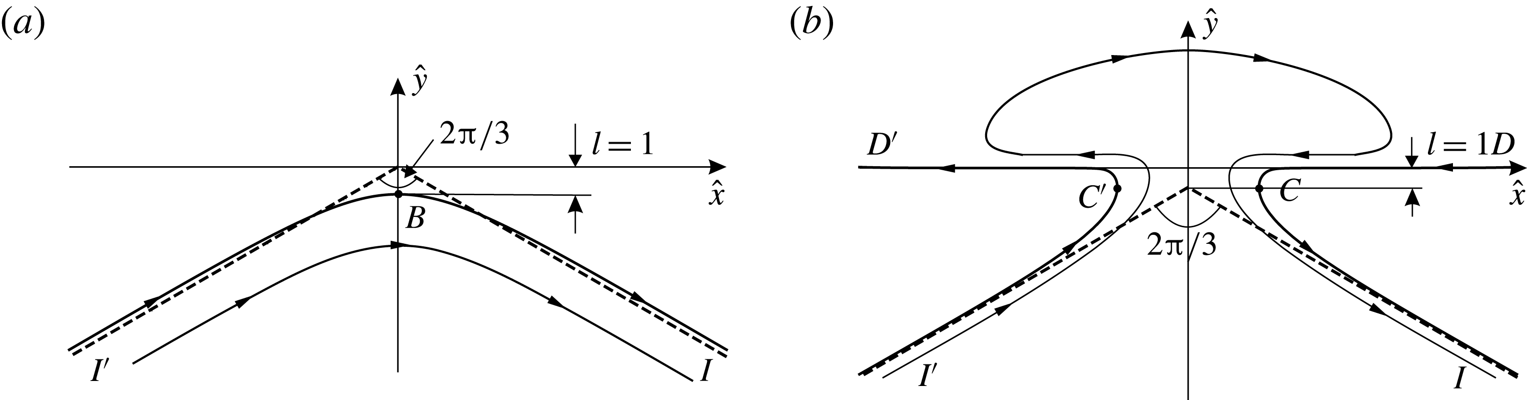
The sketches of the inner solutions for surface and interfacial waves are shown in figure 11. As one can see, these inner solutions are qualitatively different. For surface waves, the flow is similar to that in the angle of
 $120^{\circ }$
with a rounded apex. For the interfacial wave, the streamlines enter into the slot
 $C^{\prime }C$
between the inner crests and go out through the same slot; the points
 $D^{\prime }$
and
 $D$
at infinity are the stagnation ones with
 $\unicode[STIX]{x1D703}=\unicode[STIX]{x03C0}$
and
 $\unicode[STIX]{x1D703}=-\unicode[STIX]{x03C0}$
, respectively. On the streamlines
 $D^{\prime }C^{\prime }I^{\prime }$
and
 $DCI$
, the ordinate
 $y$
decreases monotonically from zero to
 $-\infty$
. For surface waves, the inner solution forms near the upper crest
 $B$
; for interfacial waves, the inner solution does so near the inner crests
 $C$
and
 $C^{\prime }$
. It is also worthwhile to mention the difference between the asymptotes:
 $$\begin{eqnarray}\displaystyle {\hat{y}}=-\frac{|\hat{x}|}{\sqrt{3}}~\text{(for surface waves)},\quad {\hat{y}}=-\frac{|\hat{x}|}{\sqrt{3}}-1~\text{(for interfacial waves)}. & & \displaystyle\end{eqnarray}$$
For surface waves, the asymptote (6.16a
) was established by Longuet-Higgins & Fox (Reference Longuet-Higgins and Fox1977). For interfacial waves, according to figure 10, the asymptote (6.16a
) seems to be shifted by one unit downwards from the vertical benchmark
 $h_{0}=c^{2}/2$
. For surface waves, the asymptote always intersects the boundary close to the almost limiting configuration; for interfacial waves, according to figure 10, this seems not to be the case.
However, there exist some general features, namely, the vertical benchmarks for both flows are the same,
 $h_{0}=c^{2}/2$
; the formulae for the natural scales are similar. In the dimensional form, they are as follows:
 $$\begin{eqnarray}\displaystyle l=\frac{q_{B}^{2}}{2g}~\text{(for surface waves)},\quad l=\frac{(q_{C}^{-})^{2}}{2g(1-\unicode[STIX]{x1D70C})}~\text{(for interfacial waves)}. & & \displaystyle\end{eqnarray}$$
In addition, the boundary conditions on the free surfaces
 $I^{\prime }BI$
and
 $I^{\prime }C^{\prime }D^{\prime }DCI$
are absolutely identical: both free surfaces are streamlines on which equation (6.9) of constant pressure is fulfilled.
6.4 Limiting configurations
The results obtained in §§ 6.2 and 6.3 allow us to predict easily the sketch of the limiting interfacial configuration. Indeed, it is evident that, for a fixed
 $\unicode[STIX]{x1D70C}$
, the limiting configuration takes place when the length
 $l$
defined by (6.15) is zero. Let
 $x_{C}$
be the abscissa of the inner crest
 $C$
. According to the last column of table 2, for the almost limiting interfacial waves
 $x_{C}\approx 3.7\times l$
. Hence if
 $l=0$
, then
 $x_{C}=0$
too. This means that the points
 $C$
and
 $C^{\prime }$
in figure 9(a) coincide. Moreover, at
 $l=0$
, the inner flow, whose sketch is shown in figure 11(b), shrinks to the point
 $C$
coinciding with
 $C^{\prime }$
. However, this shrinking conserves the directions of the slope
 $\unicode[STIX]{x1D703}$
at the infinitely remote points
 $D^{\prime }$
,
 $D$
and
 $I^{\prime }$
,
 $I$
. This reasoning naturally leads to the conclusion that the sketch of the limiting configuration is as shown in figure 9(b). The mushroom caps of the limiting interfacial configurations are stagnation zones consisting of the particles of the lower fluid.
Evidently, if
 $s_{C}$
is the arc-abscissa of point
 $C$
, then for the limiting configurations,
 $$\begin{eqnarray}\displaystyle \unicode[STIX]{x1D703}(s_{C}-0)=-\unicode[STIX]{x03C0},\quad \unicode[STIX]{x1D703}(s_{C}+0)=-\unicode[STIX]{x03C0}/6,\quad \unicode[STIX]{x1D703}(-s_{C}+0)=\unicode[STIX]{x03C0},\quad \unicode[STIX]{x1D703}(-s_{C}-0)=\unicode[STIX]{x03C0}/6. & & \displaystyle \nonumber\\ \displaystyle & & \displaystyle\end{eqnarray}$$
Thus for the limiting interfacial configurations, the function
 $\unicode[STIX]{x1D703}(s)$
is not continuous but has jumps at the points
 $\pm s_{C}$
. Therefore, the interface is not a smooth curve, proposition 1 is not true any more, and as follows from equations (6.18a,c
),
 $|\unicode[STIX]{x1D703}|_{max}=\unicode[STIX]{x03C0}$
for the limiting case.
If the density ratio
 $\unicode[STIX]{x1D70C}=1$
(Boussinesq limit), then the points
 $(-\unicode[STIX]{x03C0}/2,0)$
and
 $(\unicode[STIX]{x03C0}/2,0)$
are those of central symmetry for the left and right half of the interface, respectively. The limiting configuration in this case must be as predicted by Grimshaw & Pullin (Reference Grimshaw and Pullin1986, figure 9). The configuration contains a periodic stagnation zone formed by both the upper and lower fluids. The zone is bounded from above and below by the two free surfaces of the highest Stokes waves with angular crests that are oppositely directed and shifted by a half-period with respect to each other.
(a) The dependences of
 $c^{2}$
on
 $H$
for different values of
 $\unicode[STIX]{x1D70C}$
from table 2. The upper parts of curves 1–3 (b) and 4–6 (c). The points indicate the pairs
 $(H,c^{2})$
for Holyer’s limiting configurations with
 $|\unicode[STIX]{x1D703}|_{max}=\unicode[STIX]{x03C0}/2$
(Holyer Reference Holyer1979).

6.5 The dependences of the phase speed on the wave steepness for interfacial waves
It is well known that, for surface waves, the wave steepness
 $H$
is one of the parameters that define the wave uniquely. As was shown by Grimshaw & Pullin (Reference Grimshaw and Pullin1986) and Turner & Vanden-Broeck (Reference Turner and Vanden-Broeck1986), for interfacial waves this is not the case. In figure 12(a), we demonstrate the dependences of
 $c^{2}$
on
 $H$
for different density ratios
 $\unicode[STIX]{x1D70C}$
. The correspondence between the numbered curves and the density ratios
 $\unicode[STIX]{x1D70C}$
can be found in table 2. For interfacial waves (numbers 2–14), the end points of all curves correspond to the almost limiting configurations with
 $\unicode[STIX]{x1D703}_{max}>179.98^{\circ }$
. As one can see, for
 $\unicode[STIX]{x1D70C}\geqslant 0.03$
, the wave steepness
 $H$
really does not define the wave uniquely. Another conclusion that can be drawn from figure 12(a) is that, generally, the phase speed
 $c$
decreases as the parameter
 $\unicode[STIX]{x1D70C}$
increases, but the fastest waves occur at
 $0.07\leqslant \unicode[STIX]{x1D70C}\leqslant 0.1$
. For the Boussinesq limit when
 $\unicode[STIX]{x1D70C}\rightarrow 1$
, the phase speed
 $c\rightarrow 0$
, and we do not number this graph.
The points in figure 12 correspond to the Holyer (Reference Holyer1979) limiting configurations (
 $|\unicode[STIX]{x1D703}|_{max}=\unicode[STIX]{x03C0}/2$
). Accurate values of the pairs
 $(H,c^{2})$
for the Holyer limit are presented in table 3.
Let us consider the case of small
 $\unicode[STIX]{x1D70C}$
in more detail. The upper parts of curves 1–3 of figure 12(a) are shown in figure 12(b). Curve 2 demonstrates that at
 $\unicode[STIX]{x1D70C}=0.01$
the pair
 $(H,c^{2})$
defines the wave uniquely, but already at
 $\unicode[STIX]{x1D70C}=0.03$
(curve 3) the uniqueness disappears. Curves 4–6 of figure 12(c) prove that, for
 $0.07<\unicode[STIX]{x1D70C}\leqslant 0.1$
, the dependences
 $c^{2}$
versus
 $H$
have points of self-intersection, which means that in this range of
 $\unicode[STIX]{x1D70C}$
there exist waves which have identical values of the wave steepness
 $H$
and the phase velocity
 $c$
but different shapes. Two such waves at
 $\unicode[STIX]{x1D70C}=0.1$
are displayed in figure 13. For the sake of comparison, the
 $x$
-axis here is located at equal vertical distances from the crest and trough (
 $y_{B}=-y_{A}$
). The values of the parameters
 $P$
,
 $|\unicode[STIX]{x1D703}|_{max}$
,
 $H$
and
 $c^{2}$
for these two waves are shown in table 4.
Two waves with the same
 $H$
and
 $c^{2}$
at
 $\unicode[STIX]{x1D70C}=0.1$
.

The pairs
 $(H,c^{2})$
for Holyer’s limiting configurations with
 $|\unicode[STIX]{x1D703}|_{max}=\unicode[STIX]{x03C0}/2$
(Holyer Reference Holyer1979).

The parameters
 $P$
,
 $|\unicode[STIX]{x1D703}|_{max}$
,
 $H$
and
 $c^{2}$
for two waves of figure 13.

7 Discussion of results and conclusions
7.1 Comparison with the work by Saffman & Yuen (Reference Saffman and Yuen1982)
Accurate computations of interfacial waves of moderate steepness were carried out by Saffman & Yuen (Reference Saffman and Yuen1982). In table 2 of their paper, these authors presented the values of the phase speed
 $$\begin{eqnarray}\displaystyle C=c\sqrt{\frac{1+\unicode[STIX]{x1D70C}}{1-\unicode[STIX]{x1D70C}}}=\sqrt{\frac{2(1+\unicode[STIX]{x1D70C})}{k}} & & \displaystyle\end{eqnarray}$$
versus
 $2\unicode[STIX]{x03C0}H$
for the density ratio
 $\unicode[STIX]{x1D70C}=0.1$
. As follows from (3.1),
 $C$
is the dimensionless phase speed non-dimensionalized with respect to the phase speed of infinitesimal waves. In table 5 (second column), we have reproduced the results by Saffman & Yuen (Reference Saffman and Yuen1982). The third to fifth columns present our computations of
 $C$
at
 $N=800$
, 1600 and 3200, where
 $N$
is the number of points which approximate the right half of the interface
 $L_{2\unicode[STIX]{x03C0}}$
.
Generating the data of table 2, Saffman & Yuen (Reference Saffman and Yuen1982) thoroughly checked their decimals, and as one can see from table 5, their check turns out to be very efficient because all these decimals are correct. In our computations, we consider
 $N=800$
as a working point number which allows us to compute the interfacial waves for any
 $0<\unicode[STIX]{x1D70C}\leqslant 1$
in the range
 $0<|\unicode[STIX]{x1D703}|_{max}\leqslant 179.98^{\circ }$
with an error less than
 $10^{-8}$
. Table 5 confirms that at
 $N=800$
we have at least eight correct decimals and at the same time demonstrates an explicit convergence of the algorithm as
 $N$
increases. The last column of table 5 shows the values of
 $|\unicode[STIX]{x1D703}|_{max}$
in order to give the reader a representation about the closeness of the waves to the limiting configuration.
At
 $N=800$
, the time for computing one wave is only several seconds but certainly the time increases with increase of
 $N$
. Nevertheless, all data of table 5 have been generated for approximately one hour on the notebook HP G1 EliteBook Folio 1040.
Continuation of table 2 from the paper by Saffman & Yuen (Reference Saffman and Yuen1982, S&Y) (
 $\unicode[STIX]{x1D70C}=0.1$
).

7.2 Comparison with the work by Turner & Vanden-Broeck (Reference Turner and Vanden-Broeck1986)
In the paper by Turner & Vanden-Broeck (Reference Turner and Vanden-Broeck1986), the most extensive numerical data were obtained for the case
 $\unicode[STIX]{x1D70C}=0.1$
. The results were displayed in figure 2 (p. 374) of their paper and a copy of this figure is shown in figure 14(a). In the notation used by Turner & Vanden-Broeck,
 $s$
is the wave steepness
 $H$
, and
 $\unicode[STIX]{x1D707}$
is the squared phase velocity
 $c^{2}$
. As one can see from figure 14(a), the authors indicate on the curve five characteristic points:
(i) a non-overhanging wave;
(ii) the wave for the Holyer limit;
(iii) the wave with the greatest overhang;
(iv) a wave with a slight overhang; and
(v) a non-overhanging wave similar to the wave (ii).
On the basis of these computations, the authors conjectured (p. 371) that ‘an alternation between non-overhanging and overhanging waves continues indefinitely as one proceeds along the solution branch’. We have digitized the graph of figure 14(a) and plotted it together with our results in figure 14(b). As one can see, our computations do not confirm the conjecture by Turner & Vanden-Broeck (Reference Turner and Vanden-Broeck1986), but as was demonstrated in § 6.4, they confirm the conjecture by Saffman & Yuen (Reference Saffman and Yuen1982) that the overhanging waves continue to exist until the interface starts to touch itself.
(a) A copy of figure 2 from the paper by Turner & Vanden-Broeck (Reference Turner and Vanden-Broeck1986). (b) Comparison of our results with those in (a): the point indicates the Holyer limit; squares correspond to the data of table 5.

7.3 Conclusions
In this paper, we have studied progressive gravity waves at the interface between two unbounded fluids of different densities. The main concern is to determine the structure of the almost limiting configurations for overhanging waves and to make a correct prediction about limiting configurations. New results of the paper are as follows.
(i) A rigorous proof that the inclination angle
$\unicode[STIX]{x1D703}$
of the interface is in the range
$-\unicode[STIX]{x03C0}<\unicode[STIX]{x1D703}<\unicode[STIX]{x03C0}$
(proposition 1 in § 3).(ii) A compact mathematical formulation for the problems of interfacial waves (§ 4, equation (4.23)).
(iii) A new method of solving nonlinear boundary-value problems based on solving a series of corresponding linear boundary-value problems (§ 5 and appendix A).
(iv) Computations of the almost limiting mushroom-shaped waves with
$|\unicode[STIX]{x1D703}|_{max}>179.98^{\circ }$
(§ 6.2, figure 7).(v) Numerical evidence that, for any
$\unicode[STIX]{x1D70C}\in (0,1]$
, the level
$h_{0}=c^{2}/2$
is the height of the almost flat undersides of the mushroom caps (§ 6.2, figures 8 and 9
a).(vi) The concepts of the inner crest and the inner solution near the inner crest. Numerical evidence that the vertical distance,
$l$
, from the level
$h_{0}=c^{2}/2$
to the inner crest is a natural scale for the inner solutions (§ 6.3, figures 6
b and 10).(vii) The structure of the inner solutions (§ 6.3, figure 11 b).
(viii) A well-grounded conjecture about the structure of limiting configurations for any
$\unicode[STIX]{x1D70C}\in (0,1]$
(§ 6.4, figure 9
b). The structure is characterized by the formation of a stagnation zone bounded by a part of the interface, whereas for limiting surface waves (
$\unicode[STIX]{x1D70C}=0$
), only one stagnation point appears at the free surface.(ix) Numerical evidence that there exist overhanging and non-overhanging interfacial waves which have the same wavelength
$\unicode[STIX]{x1D706}$
, phase speed
$c$
and wave steepness
$H$
(§ 6.5, figure 13).(x) Confirmation of the conjectures by Saffman & Yuen (Reference Saffman and Yuen1982) and Grimshaw & Pullin (Reference Grimshaw and Pullin1986, figure 10) that the overhanging waves continue to exist until the interface starts to touch itself.


Acknowledgement
The work was supported by the Russian Science Foundation, project number 14-19-01633.
Appendix A. Details of the numerical algorithm for discretizing and solving problem 2
A.1 Computation of the integrals of Cauchy type by the method of complex splines
In the complex plane
 $t=\unicode[STIX]{x1D709}+\text{i}\unicode[STIX]{x1D702}$
, consider a closed smooth contour
 $C$
without self-intersections and a complex-valued function
 $\unicode[STIX]{x1D714}(u)$
(
 $u\in C$
) of the points
 $u$
of this contour. We need to compute the integral of Cauchy type
 $$\begin{eqnarray}\displaystyle \unicode[STIX]{x1D6F7}(t)=\frac{1}{2\unicode[STIX]{x03C0}\text{i}}\oint _{C}\frac{\unicode[STIX]{x1D714}(u)\,\text{d}u}{u-t} & & \displaystyle\end{eqnarray}$$
for any point
 $t$
of the complex plane.
Let
 $t_{1},t_{2},\ldots ,t_{N}=t_{1}$
be points on
 $C$
arranged in anticlockwise order, separating
 $C$
into arcs
 $C_{n}$
, with
 $C_{n}$
being the arc from
 $t_{n}$
to
 $t_{n+1}$
 $(n=\overline{1,N-1})$
. The notation in parentheses means that
 $n$
changes from 1 to
 $N-1$
with step 1. Since
 $t_{N}=t_{1}$
, the general number of different points on
 $C$
is
 $N-1$
. For this subdivision
 $\unicode[STIX]{x1D6E5}$
of
 $C$
, we form a complex spline
 $\unicode[STIX]{x1D714}_{\unicode[STIX]{x1D6E5}}(u)$
on
 $C$
of order
 $r$
composed of complex
 $r$
-degree polynomials in powers of
 $u$
. These polynomials we denote by
 $\unicode[STIX]{x1D714}_{\unicode[STIX]{x1D6E5},n}(u)$
,
 $n=\overline{1,N-1}$
. The polynomials contain
 $(N-1)(r+1)$
complex unknown coefficients which are chosen so that the interpolation function
 $\unicode[STIX]{x1D714}_{\unicode[STIX]{x1D6E5}}(u)$
is continuous and has continuous derivatives up to order
 $r-1$
on
 $C$
. In this paper, we shall use the cubic spline interpolation
 $(r=3)$
and the linear interpolation
 $(r=1)$
. We should note that the algorithms for constructing the complex cubic splines on a closed contour and periodic cubic splines on a line segment are absolutely identical (see Ahlberg, Nilson & Walsh Reference Ahlberg, Nilson and Walsh1967). For the complex cubic splines, one needs only to consider the values
 $t_{n}$
and
 $\unicode[STIX]{x1D714}_{n}=\unicode[STIX]{x1D714}(t_{n})$
(
 $n=\overline{1,N}$
) as complex numbers (
 $t_{N}=t_{1}$
is included in the set of knots). For the linear splines, we have an explicit representation of the polynomials:
 $$\begin{eqnarray}\displaystyle \unicode[STIX]{x1D714}_{\unicode[STIX]{x1D6E5},n}(u)=\unicode[STIX]{x1D714}_{n+1}\frac{u-t_{n}}{t_{n+1}-t_{n}}-\unicode[STIX]{x1D714}_{n}\frac{u-t_{n+1}}{t_{n+1}-t_{n}},\quad n=\overline{1,N-1}. & & \displaystyle\end{eqnarray}$$
In the paper by Ahlberg, Nilson & Walsh (Reference Ahlberg, Nilson and Walsh1969), a compact formula (14) was deduced for computing the integral (A 1):
 $$\begin{eqnarray}\displaystyle \unicode[STIX]{x1D6F7}_{\unicode[STIX]{x1D6E5}}(t)=\frac{1}{2\unicode[STIX]{x03C0}\text{i}}\oint _{C}\frac{\unicode[STIX]{x1D714}_{\unicode[STIX]{x1D6E5}}(u)\,\text{d}u}{u-t}=\frac{1}{2\unicode[STIX]{x03C0}\text{i}}\mathop{\sum }_{n=1}^{N-1}\unicode[STIX]{x1D714}_{\unicode[STIX]{x1D6E5},n}(t)\log \frac{t-t_{n+1}}{t-t_{n}}, & & \displaystyle\end{eqnarray}$$
which is correct for the complex splines of any order. Formula (A 3) from Ahlberg et al. (Reference Ahlberg, Nilson and Walsh1969) is a convenient tool for calculating the integrals of Cauchy type over closed contours.
Estimates of errors of the representations
 $\unicode[STIX]{x1D714}(u)=\unicode[STIX]{x1D714}_{\unicode[STIX]{x1D6E5}}(u)$
and
 $\unicode[STIX]{x1D6F7}(t)=\unicode[STIX]{x1D6F7}_{\unicode[STIX]{x1D6E5}}(t)$
can be found in Ahlberg et al. (Reference Ahlberg, Nilson and Walsh1967) (for complex cubic splines) and in Atkinson (Reference Atkinson1972) (for complex linear splines). In this paper, we do not dwell on these estimates, but an obvious remark that the interpolation by cubic spline is much more accurate than that by linear splines is yet necessary.
To discretize problem 2, we should be able to compute the principal values
 $\langle \unicode[STIX]{x1D6F7}\rangle (t)$
of the Cauchy-type integrals directly at the knots
 $t_{n}$
,
 $n=\overline{1,N-1}$
. Let
 $\unicode[STIX]{x1D6FE}_{n}$
be the angles between the tangent line at the knots
 $t_{n}$
of the contour
 $C$
and the
 $\unicode[STIX]{x1D709}$
-axis. It is clear that
 $$\begin{eqnarray}\displaystyle \langle \unicode[STIX]{x1D6F7}\rangle (t_{m})=\lim _{\unicode[STIX]{x1D700}\,\rightarrow \,+0}{\textstyle \frac{1}{2}}[\unicode[STIX]{x1D6F7}(t_{m}+\text{i}\unicode[STIX]{x1D700}\text{e}^{\text{i}\unicode[STIX]{x1D6FE}_{m}})+\unicode[STIX]{x1D6F7}(t_{m}-\text{i}\unicode[STIX]{x1D700}\text{e}^{\text{i}\unicode[STIX]{x1D6FE}_{m}})],\quad m=\overline{1,N-1}. & & \displaystyle\end{eqnarray}$$
Now, we introduce the functions
 $E_{n}(t)$
, which are defined for any
 $t$
of the complex plane
 $t=\unicode[STIX]{x1D709}+\text{i}\unicode[STIX]{x1D702}$
:
 $$\begin{eqnarray}\displaystyle E_{n}(t)=\left\{\begin{array}{@{}ll@{}}\displaystyle \frac{1}{2\unicode[STIX]{x03C0}\text{i}}\log \frac{t-t_{n+1}}{t-t_{n}} & \text{if}~t\neq t_{n}\cup t\neq t_{n+1},\\ \displaystyle \frac{1}{4\unicode[STIX]{x03C0}\text{i}}\left(\log \frac{t-t_{n+1}}{\text{i}\text{e}^{\text{i}\unicode[STIX]{x1D6FE}_{n}}}+\log \frac{t-t_{n+1}}{-\text{i}\text{e}^{\text{i}\unicode[STIX]{x1D6FE}_{n}}}\right) & \text{if}~t=t_{n},\\ \displaystyle \frac{1}{4\unicode[STIX]{x03C0}\text{i}}\left(\log \frac{\text{i}\text{e}^{\text{i}\unicode[STIX]{x1D6FE}_{n+1}}}{t-t_{n}}+\log \frac{-\text{i}\text{e}^{\text{i}\unicode[STIX]{x1D6FE}_{n+1}}}{t-t_{n}}\right) & \text{if}~t=t_{n+1},\end{array}\right. & & \displaystyle\end{eqnarray}$$
where
 $n=\overline{1,N-1}$
and the standard branch of the logarithm with the cut along the negative part of the
 $\unicode[STIX]{x1D709}$
-axis is chosen, i.e.
 $$\begin{eqnarray}\displaystyle \log \unicode[STIX]{x1D701}=\log |\unicode[STIX]{x1D701}|+\text{i}\arg \unicode[STIX]{x1D701},\quad -\unicode[STIX]{x03C0}<\arg \unicode[STIX]{x1D701}\leqslant \unicode[STIX]{x03C0}. & & \displaystyle\end{eqnarray}$$
Taking into account the continuity of the approximation
 $\unicode[STIX]{x1D714}_{\unicode[STIX]{x1D6E5}}(u)$
on the contour
 $C$
, one can easily demonstrate that
 $$\begin{eqnarray}\displaystyle \langle \unicode[STIX]{x1D6F7}_{\unicode[STIX]{x1D6E5}}\rangle (t_{m})=\mathop{\sum }_{n=1}^{N-1}\unicode[STIX]{x1D714}_{\unicode[STIX]{x1D6E5},n}(t_{m})E_{n}(t_{m}),\quad m=\overline{1,N}, & & \displaystyle\end{eqnarray}$$
these representations being correct for the complex spline approximation
 $\unicode[STIX]{x1D714}_{\unicode[STIX]{x1D6E5}}(u)$
of any order. For the linear complex spline approximation (
 $r=1$
), by making use of (A 2), formula (A 7) can be rewritten in the following manner:
 $$\begin{eqnarray}\displaystyle \langle \unicode[STIX]{x1D6F7}_{\unicode[STIX]{x1D6E5}}\rangle (t_{m})=\mathop{\sum }_{n=1}^{N}\unicode[STIX]{x1D714}_{n}G_{n}(t_{m}),\quad m=\overline{1,N}, & & \displaystyle\end{eqnarray}$$
where
 $$\begin{eqnarray}\displaystyle G_{n}(t)=\left\{\begin{array}{@{}ll@{}}\displaystyle -\frac{t-t_{2}}{t_{2}-t_{1}}E_{1}(t) & \text{for}~n=1,\\ \displaystyle \frac{t-t_{n-1}}{t_{n}-t_{n-1}}E_{n-1}(t)-\frac{t-t_{n+1}}{t_{n+1}-t_{n}}E_{n}(t) & \text{for}~2\leqslant n\leqslant N-1,\\ \displaystyle \frac{t-t_{N-1}}{t_{N}-t_{N-1}}E_{N-1}(t) & \text{for}~n=N.\end{array}\right. & & \displaystyle\end{eqnarray}$$
A.2 Discretization of functions included in the formulation of problem 2
Let the right half of the line
 $L_{2\unicode[STIX]{x03C0}}$
be approximated by a system of points
 $z_{n}=x_{n}+\text{i}y_{n}$
(
 $n=\overline{1,N}$
) arranged from
 $B$
to
 $A$
. The point
 $z_{1}$
coincides with
 $B$
, and the point
 $z_{N}$
coincides with
 $A$
. This means that
 $\text{Re}\,z_{1}=x_{1}=0$
and
 $\text{Re}\,z_{N}=x_{N}=\unicode[STIX]{x03C0}$
.
To draw a smooth line through the system, we use the chord parametrization by introducing the mesh of knots
 $$\begin{eqnarray}\displaystyle \unicode[STIX]{x1D6FC}_{1}=0,\quad \unicode[STIX]{x1D6FC}_{n+1}=\unicode[STIX]{x1D6FC}_{n}+\sqrt{(x_{n+1}-x_{n})^{2}+(y_{n+1}-y_{n})^{2}},\quad n=\overline{1,N-1}, & & \displaystyle\end{eqnarray}$$
and constructing on this mesh the cubic splines
 $x(\unicode[STIX]{x1D6FC})$
and
 $y(\unicode[STIX]{x1D6FC})$
with the values
 $x_{n}$
and
 $y_{n}$
at the knots
 $\unicode[STIX]{x1D6FC}_{n}$
(
 $n=\overline{1,N}$
), respectively. The boundary conditions for these splines are
 $$\begin{eqnarray}\displaystyle x^{\prime \prime }(\unicode[STIX]{x1D6FC}_{1})=x^{\prime \prime }(\unicode[STIX]{x1D6FC}_{N})=0,\quad y^{\prime }(\unicode[STIX]{x1D6FC}_{1})=y^{\prime }(\unicode[STIX]{x1D6FC}_{N})=0. & & \displaystyle\end{eqnarray}$$
As a result, we have the functions
 $x(\unicode[STIX]{x1D6FC})$
and
 $y(\unicode[STIX]{x1D6FC})$
, which are defined on the interval
 $[\unicode[STIX]{x1D6FC}_{1},\unicode[STIX]{x1D6FC}_{N}]$
. Extending these functions onto the whole
 $\unicode[STIX]{x1D6FC}$
-axis by the rules
 $$\begin{eqnarray}\displaystyle x(-\unicode[STIX]{x1D6FC})=-x(\unicode[STIX]{x1D6FC}),\quad x(\unicode[STIX]{x1D6FC}+2\unicode[STIX]{x1D6FC}_{N})=x(\unicode[STIX]{x1D6FC})+2\unicode[STIX]{x03C0},\quad y(-\unicode[STIX]{x1D6FC})=y(\unicode[STIX]{x1D6FC}),\quad y(\unicode[STIX]{x1D6FC}+2\unicode[STIX]{x1D6FC}_{N})=y(\unicode[STIX]{x1D6FC}), & & \displaystyle \nonumber\\ \displaystyle & & \displaystyle\end{eqnarray}$$
we obtain a parametric representation of a smooth,
 $2\unicode[STIX]{x03C0}$
-periodic and symmetric line
 $L$
with continuous curvature.
Assume now that the line
 $L$
, the parameter
 $k$
and the function
 $F(z)$
determined from (4.13) are an approximate solution to problem 1. To discretize problem 2, one needs to construct discrete analogues of the functions and to find the values of the parameters included in the formulation of the problem, namely,
 $a(s)$
,
 $b(s)$
,
 $c(s)$
,
 $d(s)$
,
 $U(s)$
,
 $S_{L}$
,
 $P_{L}$
and
 $R(s)$
, where
 $s$
is the arc-coordinate which labels the point
 $z$
on
 $L$
. The coordinate
 $s$
can be easily replaced by
 $\unicode[STIX]{x1D6FC}$
, but, making the discretization, we take as an argument the number
 $n$
of the point
 $z_{n}$
,
 $n=\overline{1,N}$
. For example,
 $\unicode[STIX]{x1D703}(s)$
is replaced by the set of values
 $\unicode[STIX]{x1D703}_{n}$
, which are the angles between the tangent line at the knots
 $z_{n}$
of the line
 $L$
and the
 $x$
-axis. Thus, we compute
 $$\begin{eqnarray}\displaystyle \unicode[STIX]{x1D703}_{n}=\arg [x^{\prime }(\unicode[STIX]{x1D6FC}_{n})+\text{i}y^{\prime }(\unicode[STIX]{x1D6FC}_{n})],\quad \unicode[STIX]{x1D706}_{n}=(ky_{n}+\unicode[STIX]{x1D70C}-1)\text{e}^{2\text{i}\unicode[STIX]{x1D703}_{n}},\quad n=\overline{1,N} & & \displaystyle\end{eqnarray}$$
and the curvatures
 $$\begin{eqnarray}\displaystyle K_{n}=\frac{y^{\prime \prime }(\unicode[STIX]{x1D6FC}_{n})x^{\prime }(\unicode[STIX]{x1D6FC}_{n})-x^{\prime \prime }(\unicode[STIX]{x1D6FC}_{n})y^{\prime }(\unicode[STIX]{x1D6FC}_{n})}{\{[x^{\prime }(\unicode[STIX]{x1D6FC}_{n})]^{2}+[y^{\prime }(\unicode[STIX]{x1D6FC}_{n})]^{2}\}^{3/2}},\quad n=\overline{1,N}. & & \displaystyle\end{eqnarray}$$
After determining these values, we calculate
 $a_{n}$
,
 $b_{n}$
and
 $c_{n}$
by formulae (5.32). We find also the arc-coordinates
 $s_{n}$
:
 $$\begin{eqnarray}\displaystyle s_{1}=0,\quad s_{n+1}=s_{n}+\int _{\unicode[STIX]{x1D6FC}_{n}}^{\unicode[STIX]{x1D6FC}_{n+1}}\sqrt{[x^{\prime }(\unicode[STIX]{x1D6FC}_{n})]^{2}+[y^{\prime }(\unicode[STIX]{x1D6FC}_{n})]^{2}}\,\text{d}\unicode[STIX]{x1D6FC},\quad n=\overline{1,N-1}. & & \displaystyle\end{eqnarray}$$
To calculate accurately the integrals in (A 15b
), we subdivide the intervals
 $[\unicode[STIX]{x1D6FC}_{n},\unicode[STIX]{x1D6FC}_{n+1}]$
uniformly into 10 parts and use Simpson’s rule. The half-perimeter of the line
 $L$
is evidently
 $l_{s}=s_{N}$
; then the parameter
 $P_{L}$
on the right-hand side of (5.35b
) is
 $P_{L}=l_{s}/\unicode[STIX]{x03C0}$
. The values
 $s_{n}$
and
 $l_{s}$
are necessary to discretize (5.35a
). The parameter
 $S_{L}$
on the right-hand side of (5.35a
) can be found from the formula
 $$\begin{eqnarray}\displaystyle S_{L}=2\int _{0}^{\unicode[STIX]{x1D6FC}_{N}}y(\unicode[STIX]{x1D6FC})x^{\prime }(\unicode[STIX]{x1D6FC})\,\text{d}\unicode[STIX]{x1D6FC}. & & \displaystyle\end{eqnarray}$$
On each interval
 $[\unicode[STIX]{x1D6FC}_{n},\unicode[STIX]{x1D6FC}_{n+1}]$
, the integrand in (A 16) is a polynomial of fifth degree, which allows the analytical computation of
 $S_{L}$
to be carried out.
To find the discrete analogues of the functions
 $d(s)$
,
 $U(s)$
and
 $R(s)$
, i.e the values
 $d_{n}$
,
 $U_{n}$
and
 $R_{n}$
, one needs to determine
 $\langle F\rangle _{n}$
, i.e. the principal values of the integral (4.13) at the points
 $z_{n}$
. To evaluate
 $\langle F\rangle _{n}$
, we map conformally one period of the flow domain, shown in figure 1, onto the plane
 $t=\unicode[STIX]{x1D709}+\text{i}\unicode[STIX]{x1D702}$
by means of the function
 $t=\text{e}^{\text{i}z}$
. Under this mapping, the image of the interfacial line
 $L_{2\unicode[STIX]{x03C0}}$
is a closed contour
 $C$
, which is symmetric with respect to the
 $\unicode[STIX]{x1D709}$
-axis. The upper and lower flow domains
 $D_{1}$
and
 $D_{2}$
transform into the interior and exterior of the contour
 $C$
, respectively. The upper and lower infinities
 $I_{1}$
and
 $I_{2}$
in the
 $z$
-plane correspond to the points
 $t=0$
and
 $t=\infty$
in the
 $t$
-plane. The images of the points
 $z_{n}$
are the points
 $t_{n}=\exp (\text{i}z_{n})$
(
 $n=\overline{1,N}$
), located on the upper half of the contour
 $C$
(compare figure 1 of the main text and figure 15).
The plane
 $t=\unicode[STIX]{x1D709}+\text{i}\unicode[STIX]{x1D702}$
for computing the integrals of Cauchy type.

The change of variable
 $z=-\text{i}\log t$
converts the integral (4.13) into the integral of Cauchy type:
 $$\begin{eqnarray}\displaystyle F(t)=\frac{1}{2\unicode[STIX]{x03C0}\text{i}}\oint _{C}\frac{\unicode[STIX]{x1D706}(u)\,\text{d}u}{u-t}, & & \displaystyle\end{eqnarray}$$
where
 $\unicode[STIX]{x1D706}(u)$
satisfies the symmetry condition
 $$\begin{eqnarray}\displaystyle \unicode[STIX]{x1D706}(\bar{u})=\overline{\unicode[STIX]{x1D706}(u)},\quad u\in C, & & \displaystyle\end{eqnarray}$$
which follows from (4.14). It is to be noted that the condition (A 18) implies that
 $$\begin{eqnarray}\displaystyle \text{Im}\,\unicode[STIX]{x1D706}(t_{1})=\text{Im}\,\unicode[STIX]{x1D706}(t_{N})=0. & & \displaystyle\end{eqnarray}$$
So, to compute
 $\langle F\rangle _{n}$
, we can use the technique described in § A.1. It can be easily demonstrated that the angle
 $\unicode[STIX]{x1D6FE}$
between the tangent line to the contour
 $C$
and the
 $\unicode[STIX]{x1D709}$
-axis is
 $\unicode[STIX]{x1D6FE}=\unicode[STIX]{x1D703}+x+\unicode[STIX]{x03C0}/2$
,
 $x+\text{i}y\in L_{2\unicode[STIX]{x03C0}}$
.
First, we find
 $\unicode[STIX]{x1D6FE}_{n}=\unicode[STIX]{x1D703}_{n}+x_{n}+\unicode[STIX]{x03C0}/2$
and determine the functions
 $E_{n}(t)$
by formulae (A 5). Second, on the mesh of knots
 $t_{n}$
,
 $n=\overline{1,N}$
, we construct the complex cubic spline
 $\unicode[STIX]{x1D706}_{\unicode[STIX]{x1D6E5}}(u)$
with the values
 $\unicode[STIX]{x1D706}_{n}$
at the knots
 $t_{n}$
. The boundary conditions for this spline are
 $$\begin{eqnarray}\displaystyle \text{Im}\,\unicode[STIX]{x1D706}_{\unicode[STIX]{x1D6E5}}^{\prime }(t_{1})=\text{Im}\,\unicode[STIX]{x1D706}_{\unicode[STIX]{x1D6E5}}^{\prime }(t_{N})=0,\quad \text{Im}\,\unicode[STIX]{x1D706}_{\unicode[STIX]{x1D6E5}}^{\prime \prime }(t_{1})=\text{Im}\,\unicode[STIX]{x1D706}_{\unicode[STIX]{x1D6E5}}^{\prime \prime }(t_{N})=0. & & \displaystyle\end{eqnarray}$$
To construct such a cubic spline, we proceed in the following manner. We compute three complex cubic splines
 $\unicode[STIX]{x1D706}_{0\unicode[STIX]{x1D6E5}}(u)$
,
 $\unicode[STIX]{x1D706}_{1\unicode[STIX]{x1D6E5}}(u)$
and
 $\unicode[STIX]{x1D706}_{2\unicode[STIX]{x1D6E5}}(u)$
which satisfy the conditions
 $$\begin{eqnarray}\displaystyle \unicode[STIX]{x1D706}_{0\unicode[STIX]{x1D6E5}}(t_{n})=\unicode[STIX]{x1D706}_{n}\quad (n=\overline{1,N}),\quad \unicode[STIX]{x1D706}_{0\unicode[STIX]{x1D6E5}}^{\prime \prime }(t_{1})=\unicode[STIX]{x1D706}_{0\unicode[STIX]{x1D6E5}}^{\prime \prime }(t_{N})=0, & & \displaystyle\end{eqnarray}$$
 $$\begin{eqnarray}\displaystyle \unicode[STIX]{x1D706}_{1\unicode[STIX]{x1D6E5}}(t_{n})=0\quad (n=\overline{1,N}),\quad \unicode[STIX]{x1D706}_{1\unicode[STIX]{x1D6E5}}^{\prime \prime }(t_{1})=1,\quad \unicode[STIX]{x1D706}_{1\unicode[STIX]{x1D6E5}}^{\prime \prime }(t_{N})=0, & & \displaystyle\end{eqnarray}$$
 $$\begin{eqnarray}\displaystyle \unicode[STIX]{x1D706}_{2\unicode[STIX]{x1D6E5}}(t_{n})=0\quad (n=\overline{1,N}),\quad \unicode[STIX]{x1D706}_{2\unicode[STIX]{x1D6E5}}^{\prime \prime }(t_{1})=0,\quad \unicode[STIX]{x1D706}_{1\unicode[STIX]{x1D6E5}}^{\prime \prime }(t_{N})=1. & & \displaystyle\end{eqnarray}$$
The algorithm for computing the complex cubic splines with specified second derivatives at the end points is absolutely analogous to that for the ordinary cubic splines on a line segment. After finding
 $\unicode[STIX]{x1D706}_{0\unicode[STIX]{x1D6E5}}(u)$
,
 $\unicode[STIX]{x1D706}_{1\unicode[STIX]{x1D6E5}}(u)$
and
 $\unicode[STIX]{x1D706}_{2\unicode[STIX]{x1D6E5}}(u)$
, we seek
 $\unicode[STIX]{x1D706}_{\unicode[STIX]{x1D6E5}}(u)$
in the form
 $$\begin{eqnarray}\displaystyle \unicode[STIX]{x1D706}_{\unicode[STIX]{x1D6E5}}(u)=\unicode[STIX]{x1D6FD}_{1}\unicode[STIX]{x1D706}_{1\unicode[STIX]{x1D6E5}}(u)+\unicode[STIX]{x1D6FD}_{2}\unicode[STIX]{x1D706}_{2\unicode[STIX]{x1D6E5}}(u)+\unicode[STIX]{x1D706}_{0\unicode[STIX]{x1D6E5}}(u), & & \displaystyle\end{eqnarray}$$
where
 $\unicode[STIX]{x1D6FD}_{1}$
and
 $\unicode[STIX]{x1D6FD}_{2}$
are unknown real parameters. It is clear that
 $\unicode[STIX]{x1D706}_{\unicode[STIX]{x1D6E5}}(u)$
satisfies the boundary conditions (A 20b
). The remaining operation is to determine
 $\unicode[STIX]{x1D6FD}_{1}$
and
 $\unicode[STIX]{x1D6FD}_{2}$
from the boundary conditions (A 20a
).
The function
 $\unicode[STIX]{x1D706}_{\unicode[STIX]{x1D6E5}}(u)$
is defined on the upper half of the contour
 $C$
. The relation (A 19) and the boundary conditions (A 20) provide that the extension of the function
 $\unicode[STIX]{x1D706}_{\unicode[STIX]{x1D6E5}}(u)$
onto the whole contour
 $C$
by the rule (A 18) is continuous and has continuous derivatives up to second order at the break points
 $t_{n}$
and at their symmetric counterparts
 $\overline{t_{n}}$
.
Now, using (A 7) and taking into account the symmetry conditions (A 18), we calculate
 $$\begin{eqnarray}\displaystyle \langle F\rangle _{m}=\mathop{\sum }_{n=1}^{N}\unicode[STIX]{x1D706}_{\unicode[STIX]{x1D6E5},n}(t_{m})\,E_{n}(t_{m})+\mathop{\sum }_{n=1}^{N}\overline{\unicode[STIX]{x1D706}_{\unicode[STIX]{x1D6E5},n}(\overline{t_{m}})}\,\overline{E_{n}(\overline{t_{m}})},\quad m=\overline{1,N}. & & \displaystyle\end{eqnarray}$$
After that, with the help of (5.14c
) and (5.28b
), we compute
 $R_{n}$
and
 $U_{n}$
.
To calculate
 $d_{n}$
by (5.28a
), we construct the complex cubic spline
 $\langle F\rangle _{\unicode[STIX]{x1D6E5}}(u)$
with the values
 $\langle F\rangle _{n}$
at the knots
 $t_{n}$
and with the same boundary conditions (A 20) as for
 $\unicode[STIX]{x1D706}_{\unicode[STIX]{x1D6E5}}(u)$
. Computing analytically the derivatives
 $\langle F\rangle _{\unicode[STIX]{x1D6E5}}^{\prime }(t_{n})$
and using the chain rule, we find
 $$\begin{eqnarray}\displaystyle d_{n}=-\frac{1}{2}\,\text{Im}\frac{\langle F\rangle _{\unicode[STIX]{x1D6E5}}^{\prime }(t_{n})t_{n}\text{e}^{\text{i}\unicode[STIX]{x1D703}_{n}}}{\langle F\rangle _{n}+1},\quad n=\overline{1,N}. & & \displaystyle\end{eqnarray}$$
At this stage, we have found the values of
 $a_{n}$
,
 $b_{n}$
,
 $c_{n}$
,
 $d_{n}$
,
 $U_{n}$
and
 $R_{n}$
, which are the discrete analogues of the functions
 $a(s)$
,
 $b(s)$
,
 $c(s)$
,
 $d(s)$
,
 $U(s)$
and
 $R(s)$
included in the formulation of problem 2. The parameters
 $S_{L}$
and
 $P_{L}$
have been found too. It is to be noted that making use of the cubic splines technique provides a high accuracy of computing the right-hand sides of equations (5.33) and (5.35). For exact solutions to problem 1, these right-hand sides are exactly zero, and their difference from zero defines the general accuracy of the solution to problem 1.
A.3 Discretization of equations (5.33) and (5.35)
Now we should discretize the left-hand sides of (5.33) and (5.35). In discretizing the left-hand side of (5.33), the accuracy is of less importance, but the computer time is of higher priority. So, discretizing the operator
 $D[\unicode[STIX]{x1D714}](s)$
, defined by (5.34), we shall use the complex linear spline interpolation (A 8). With the help of (A 9), we compute the functions
 $G_{n}(t)$
(
 $n=\overline{1,N}$
). Taking into account (A 8) and the symmetry condition
 $\unicode[STIX]{x1D714}(\bar{u})=\overline{\unicode[STIX]{x1D714}(u)}$
, we write
 $$\begin{eqnarray}\displaystyle D[\unicode[STIX]{x1D714}](s_{m})=\text{Im}\left\{U_{m}\left[\mathop{\sum }_{n=1}^{N}\unicode[STIX]{x1D714}_{n}G_{n}(t_{m})+\mathop{\sum }_{n=1}^{N}\overline{\unicode[STIX]{x1D714}_{n}}\,\overline{G_{n}(\overline{t_{m}})}\right]\right\},\quad m=\overline{1,N}. & & \displaystyle\end{eqnarray}$$
The discrete analogue of the operator
 $D[\unicode[STIX]{x1D714}](s)$
takes the form
 $$\begin{eqnarray}\displaystyle D[\unicode[STIX]{x1D714}](s_{m})=\mathop{\sum }_{n=1}^{N}A_{m,n}\,\text{Re}\,\unicode[STIX]{x1D714}_{n}+\mathop{\sum }_{n=1}^{N}B_{m,n}\,\text{Im}\,\unicode[STIX]{x1D714}_{n},\quad m=\overline{1,N}, & & \displaystyle\end{eqnarray}$$
where
 $A_{m,n}$
and
 $A_{m,n}$
are real-valued squared matrices defined as
 $$\begin{eqnarray}\displaystyle & \displaystyle A_{m,n}=\text{Im}\{U_{m}[G_{n}(t_{m})+\overline{G_{n}(\overline{t_{m}})}]\},\quad m,n=\overline{1,N}, & \displaystyle\end{eqnarray}$$
 $$\begin{eqnarray}\displaystyle & \displaystyle B_{m,n}=\text{Re}\{U_{m}[G_{n}(t_{m})-\overline{G_{n}(\overline{t_{m}})}]\},\quad m=\overline{1,N},~n=\overline{2,N-1}, & \displaystyle\end{eqnarray}$$
 $$\begin{eqnarray}\displaystyle & \displaystyle B_{m,1}=B_{m,N}=0,\quad m=\overline{1,N}, & \displaystyle\end{eqnarray}$$
and in the last formula we have taken into account the symmetry condition
 $\unicode[STIX]{x1D714}(\bar{u})=\overline{\unicode[STIX]{x1D714}(u)}$
, which implies that
 $\text{Im}\,\unicode[STIX]{x1D714}_{1}=\text{Im}\,\unicode[STIX]{x1D714}_{N}=0$
.
Solving system (5.33) and (5.35), we shall seek the function
 $\unicode[STIX]{x1D708}(\unicode[STIX]{x1D6FC})=h^{\prime }(\unicode[STIX]{x1D6FC})$
, which we approximate on the segment
 $[0,\unicode[STIX]{x1D6FC}_{N}]$
by a cubic spline with the not-a-knot condition (see de Boor Reference de Boor1978). The unknowns in this interpolation are the values
 $\unicode[STIX]{x1D708}_{n}=\unicode[STIX]{x1D708}(\unicode[STIX]{x1D6FC}_{n})$
. It is evident that
 $$\begin{eqnarray}\displaystyle h(\unicode[STIX]{x1D6FC})=h_{0}+\int _{0}^{\unicode[STIX]{x1D6FC}}\unicode[STIX]{x1D708}(\unicode[STIX]{x1D6FD})\,\text{d}\unicode[STIX]{x1D6FD}. & & \displaystyle\end{eqnarray}$$
The discrete analogue of the integral operator in (A 32) is
 $$\begin{eqnarray}\displaystyle \int _{0}^{\unicode[STIX]{x1D6FC}_{n}}\unicode[STIX]{x1D708}(\unicode[STIX]{x1D6FD})\,\text{d}\unicode[STIX]{x1D6FD}=\mathop{\sum }_{n=1}^{N}S_{m,n}\unicode[STIX]{x1D708}_{n},\quad m=\overline{1,N}, & & \displaystyle\end{eqnarray}$$
where
 $S_{m,n}$
is a squared matrix whose columns can be found by integrating in sequence the so-called fundamental splines
 $S_{n}(\unicode[STIX]{x1D6FC})$
(
 $n=\overline{1,N}$
), which take zero values at all knots except the knot with number
 $n$
where
 $S_{n}(\unicode[STIX]{x1D6FC}_{n})=1$
. The formulae for
 $S_{m,n}$
are as follows:
 $$\begin{eqnarray}\displaystyle S_{1,n}=0,\quad S_{m+1,n}=S_{m,n}+\int _{\unicode[STIX]{x1D6FC}_{m}}^{\unicode[STIX]{x1D6FC}_{m+1}}S_{n}(\unicode[STIX]{x1D6FC})\,\text{d}\unicode[STIX]{x1D6FC},\quad m=\overline{1,N-1}, & & \displaystyle\end{eqnarray}$$
the integral being computed analytically in (A 34b ).
Taking into account that
 $h^{\prime }(s)=\unicode[STIX]{x1D708}(\unicode[STIX]{x1D6FC})/\unicode[STIX]{x1D707}(\unicode[STIX]{x1D6FC})$
, where
 $\unicode[STIX]{x1D707}(\unicode[STIX]{x1D6FC})=\sqrt{[x^{\prime }(\unicode[STIX]{x1D6FC})]^{2}+[y^{\prime }(\unicode[STIX]{x1D6FC})]^{2}}$
, and introducing the notation
 $$\begin{eqnarray}\displaystyle \unicode[STIX]{x1D707}_{n}=\unicode[STIX]{x1D707}(\unicode[STIX]{x1D6FC}_{n}),\quad \unicode[STIX]{x1D708}_{N+1}=h_{0},\quad \unicode[STIX]{x1D708}_{N+2}=\unicode[STIX]{x1D6FF}k,\quad R_{N+1}=S_{L}/2,\quad R_{N+2}=P_{L}-P, & & \displaystyle\end{eqnarray}$$
we come to the following system of
 $N+2$
linear equations with
 $N+2$
unknowns:
 $$\begin{eqnarray}\displaystyle \mathop{\sum }_{n=1}^{N+2}Q_{m,n}\unicode[STIX]{x1D708}_{n}=-R_{m},\quad m=\overline{1,N+2}, & & \displaystyle\end{eqnarray}$$
where
 $$\begin{eqnarray}\displaystyle Q_{m,n} & = & \displaystyle \unicode[STIX]{x1D6FF}_{m,n}/\unicode[STIX]{x1D707}_{m}+d_{m}S_{m,n}+A_{m,n}\,\text{Re}(a_{n}/\unicode[STIX]{x1D707}_{n})+B_{m,n}\,\text{Im}(b_{n}/\unicode[STIX]{x1D707}_{n})\nonumber\\ \displaystyle & & \displaystyle +\,\mathop{\sum }_{j=1}^{N}(A_{m,j}\,\text{Re}\,b_{j}+B_{m,j}\,\text{Im}\,b_{j})S_{j,n},\quad m,n=\overline{1,N},\end{eqnarray}$$
 $\unicode[STIX]{x1D6FF}_{m,n}$
is the Kronecker delta,
 $$\begin{eqnarray}\displaystyle & \displaystyle Q_{m,N+1}=d_{m}+\mathop{\sum }_{j=1}^{N}(A_{m,j}\,\text{Re}\,b_{j}+B_{m,j}\,\text{Im}\,b_{j}),\quad m=\overline{1,N}, & \displaystyle\end{eqnarray}$$
 $$\begin{eqnarray}\displaystyle & \displaystyle Q_{m,N+2}=\mathop{\sum }_{j=1}^{N}(A_{m,j}\,\text{Re}\,c_{j}+B_{m,j}\,\text{Im}\,c_{j}),\quad m=\overline{1,N}, & \displaystyle\end{eqnarray}$$
 $$\begin{eqnarray}\displaystyle Q_{N+1,n}=(l_{s}-s_{n})S_{N,n},\quad Q_{N+2,n}=\unicode[STIX]{x1D703}_{n}S_{N,n}/\unicode[STIX]{x03C0},\quad n=\overline{1,N}, & & \displaystyle\end{eqnarray}$$
 $$\begin{eqnarray}\displaystyle Q_{N+1,N+1}=l_{s},\quad Q_{N+1,N+2}=Q_{N+2,N+1}=Q_{N+2,N+2}=0. & & \displaystyle\end{eqnarray}$$
After solving system (A 36), we determine
 $$\begin{eqnarray}\displaystyle h_{m}=\unicode[STIX]{x1D708}_{N+1}+\mathop{\sum }_{n=1}^{N}S_{m,n}\unicode[STIX]{x1D708}_{n},\quad m=\overline{1,N}. & & \displaystyle\end{eqnarray}$$
New approximations for the parameter
 $k$
and line
 $L$
are
 $$\begin{eqnarray}\displaystyle k^{new}=k+\unicode[STIX]{x1D708}_{N+2},\quad z_{n}^{new}=z_{n}+\text{i}\text{e}^{\text{i}\unicode[STIX]{x1D703}_{n}}h_{n},\quad n=\overline{1,N}. & & \displaystyle\end{eqnarray}$$