1. Introduction
Turbulent boundary layers (TBLs) subjected to severe acceleration or strong favourable pressure gradients (FPGs) are of great fundamental and technological importance. Scientifically, they elicit great interest from the points of view of scaling laws, the complex interaction between the outer and inner regions, and the relaminarization phenomenon. Although ‘relaminarization’ is often viewed as a complete reversion to laminar flow, this particular case corresponds to ‘hard’ relaminarization (for instance, when Reynolds number drops considerably and upstream turbulence is killed by dissipation, defined as the first archetype in Narasimha (Reference Narasimha1983)). This must be distinguished from ‘soft’ relaminarization, in which ‘there may be appreciable residual turbulence’ (Narasimha Reference Narasimha1983). According to Narasimha & Sreenivasan (Reference Narasimha and Sreenivasan1979) ‘reversion in such flows is primarily the result of the domination of pressure forces over nearly frozen Reynolds stresses, rather than of absorption or dissipation, although these could contribute (especially the latter near the wall)’. Furthermore, after imposing a pressure gradient in incompressible flows, an initial short region can be expected (where the standard turbulent laws, for instance the log law, are satisfied) and was defined as region (a) in Sreenivasan (Reference Sreenivasan1982). Downstream, the flow parameters exhibit significant deviations from those of the constant-pressure region but the flow still shows turbulent characteristics with large values of the wall shear stress. This region has been called ‘laminarescent’ by Schraub & Kline (Reference Schraub and Kline1965) and Sreenivasan (Reference Sreenivasan1982). Based on experiments by Patel (Reference Patel1965), Sreenivasan (Reference Sreenivasan1982) suggested that the laminarescent region started when
 ${\rm\Delta}p$
approximately attained a value of −0.005 (
 ${\rm\Delta}p=({\it\nu}\,\text{d}P/\text{d}x)/u_{{\it\tau}}^{3}$
, where
 ${\it\nu}$
is the kinematic viscosity,
 $P$
is the mean pressure and
 $u_{{\it\tau}}$
is the friction velocity). If the flow acceleration continues, the onset of laminarization can be achieved. Several studies in the past have focused on identifying the commencement of the gradual process of laminarization. Traditionally, FPG flows have been characterized by the acceleration parameter
 $K=({\it\nu}/U_{\infty }^{2})\,\text{d}U_{\infty }/\text{d}x$
, where
 $U_{\infty }$
is the free-stream velocity (Launder Reference Launder1964). For
 $K>3.0\times 10^{-6}$
, relaminarization of the turbulent flow is expected. However, Spalart’s (Reference Spalart1986) direct numerical simulation (DNS) of sink flows showed laminarization at
 $K=3.0\times 10^{-6}$
. Kline et al. (Reference Kline, Reynolds, Schraub and Runstadler1967) proposed that relaminarization in highly accelerated flows could mean the ending of bursting. They measured bursting in a boundary layer subjected to strong FPGs and inferred a critical acceleration parameter,
 $K_{c}$
, of
 $3.5\times 10^{-6}$
at which bursting ceased. Thus,
 $K$
is not a definite demarcator for deciding when relaminarization starts, since
 $K$
does not possess any boundary layer parameter (Narasimha Reference Narasimha1983). On the other hand, Patel (Reference Patel1965) suggested a critical value of −0.025 for
 ${\rm\Delta}p$
. Narasimha & Sreenivasan (Reference Narasimha and Sreenivasan1973) introduced the parameter
 ${\it\Lambda}=(-{\it\delta}\,\text{d}P/\text{d}x)/{\it\tau}_{wo}$
(where
 ${\it\delta}$
and
 $\text{d}P/\text{d}x$
are local values of the boundary layer thickness and the streamwise pressure gradient, respectively, and
 ${\it\tau}_{wo}$
is the wall shear stress at the last zero-pressure-gradient (ZPG) station, upstream of the FPG region), defined as the ratio of the pressure gradient
 $\text{d}P/\text{d}x$
to the characteristic Reynolds stress gradient
 ${\it\tau}_{wo}/{\it\delta}$
. Thus, no prior knowledge of turbulent stresses was required for describing the mean flow. For large values of
 ${\it\Lambda}$
(
 ${\geqslant}50$
), they demonstrated that the mean flow field could be split into an inner laminar sublayer and an inviscid but rotational outer layer, and used this criterion as an identifier of reversion. Bourassa & Thomas (Reference Bourassa and Thomas2009) performed experiments in an FPG boundary layer generated by a linear contraction, producing a constant peak value of the acceleration parameter (i.e.
 $K=4.4\times 10^{-6}$
) for approximately 13 local boundary layer thicknesses. They reported that, when
 ${\it\Lambda}$
was approximately 300, the boundary layer began to show behaviour related to the onset of relaminarization. A comprehensive analysis of criteria for laminarization identification can be found in Narasimha & Sreenivasan (Reference Narasimha and Sreenivasan1979).
More recently, Cal & Castillo (Reference Cal and Castillo2008) showed that a quasi-laminar state could be characterized by the pressure parameter
 ${\it\Lambda}_{{\it\delta}}=-({\it\delta}/(U_{\infty }\,\text{d}{\it\delta}/\text{d}x))\,\text{d}U_{\infty }/\text{d}x$
based on equilibrium similarity analysis. They found a critical value
 ${\it\Lambda}_{{\it\delta}}\simeq 0.47$
for the laminarization onset, at which a sudden reduction in skin friction and a redistribution of Reynolds stresses were observed. Blackwelder & Kovasznay (Reference Blackwelder and Kovasznay1972) found from experiments in a strong FPG flow that the absolute values of Reynolds shear stresses remained practically constant along a mean streamline during relaminarization but decreased when normalized by the local free-stream velocity. Similar observations were made by Sreenivasan (Reference Sreenivasan1982). Jones & Launder (Reference Jones and Launder1972) experimentally studied a sink-flow TBL for
 $K=1.5$
, 2.5 and
 $3\times 10^{-6}$
. The peak of the calculated Reynolds shear stresses
 $\overline{u^{\prime }v^{\prime }}$
(obtained from the measured mean velocity profiles and an integrated similarity equation) became gradually a smaller fraction of the measured wall shear stress as
 $K$
was increased. In experimental and theoretical studies in sink flows at mild FPGs, i.e. at
 $K=2.7$
, 3.59 and
 $5.39\times 10^{-7}$
, Jones, Marusic & Perry (Reference Jones, Marusic and Perry2001) reported logarithmic behaviours in both streamwise and spanwise Reynolds stress profiles as predicted by the fully turbulent scaling laws of Perry, Henbest & Chong (Reference Perry, Henbest and Chong1986), despite the low Reynolds numbers considered. Dixit & Ramesh (Reference Dixit and Ramesh2010) investigated large-scale organized structures in sink-flow turbulent and relaminarization boundary layers by means of hot-wire anemometry. They considered acceleration parameters,
 $K$
, in the range of
 $(0.77{-}4.52)\times 10^{-6}$
and found a systematic decrease of inclination angles of turbulent structures as the FPG increased. Owing to the shallow inclination of eddy structures in the reverse transition stage, Dixit & Ramesh (Reference Dixit and Ramesh2010) hypothesized that the contribution of the ‘leg’ eddy to the turbulent transport of mean streamwise momentum (i.e.
 $\partial (-\overline{uv})/\partial y$
) was significantly negligible in comparison with the contribution from the ‘head’ eddy. Direct and large-eddy simulations of spatially developing boundary layers under strong FPG were carried out by Piomelli & Yuan (Reference Piomelli and Yuan2013). Reynolds shear stresses significantly decreased in the acceleration region (particularly, at the location of the maximum acceleration parameter
 $K$
) showing sharper peaks.
Specifically, we seek to demonstrate and explain the unique logarithmic behaviour in the Reynolds shear stress subjected to strong FPG. The acceleration parameter
 $K$
has been kept constant for a long distance (approximately, 30 inlet TBL thicknesses) with a value of
 $4.0\times 10^{-6}$
. The present flow is thus laminarescent, confirmed by the examination of the different terms of the mean momentum equation.
2. Numerical details
As accelerating flows necessarily become thinner, associated complications in measurements can be obviated in DNS. However, the necessary mesh resolution, coupled with the need for long computational domains, makes these simulations challenging. In order to impose realistic turbulent inlet flow conditions, we employed the dynamic multiscale approach (DMA) of Araya et al. (Reference Araya, Jansen, Meneveau and Castillo2011). The rescaling–recycling method by Lund, Wu & Squires (Reference Lund, Wu and Squires1998) prescribes time-dependent turbulence information at the inlet plane using a flow scaled from the downstream solution at the recycle plane. The DMA differs from the original rescaling–recycling method of Lund et al. (Reference Lund, Wu and Squires1998) in two ways: (i) different scaling functions in the inner and outer regions of the TBL (i.e. multiscale) are imposed; and (ii) the friction velocity
 $u_{{\it\tau}}=\sqrt{{\it\tau}_{w}/{\it\rho}}$
(where
 ${\it\tau}_{w}$
is the wall shear stress and
 ${\it\rho}$
is the fluid density) and flow parameters at the inlet of the computational domain are deduced dynamically by using a ‘test plane’ located between the inlet and recycle planes (Araya et al.
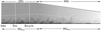
Reference Araya, Jansen, Meneveau and Castillo2011). Figure 1 shows the computational domain consisting of a ZPG region of length
 $20{\it\delta}_{inlet}$
followed by an FPG region of length
 $40{\it\delta}_{inlet}$
, where
 ${\it\delta}_{inlet}$
is the 99 % TBL thickness at the inlet. The dashed line represents the edge of the boundary layer. The inlet, test and recycle planes are located in the ZPG region, immediately preceding the FPG region. The dimensions of the composite computational domain (
 $L_{x}$
,
 $L_{y}$
and
 $L_{z}$
) are
 $60{\it\delta}_{inlet}$
,
 $3{\it\delta}_{inlet}$
and
 $3{\it\delta}_{inlet}$
along the streamwise (
 $x$
), wall-normal (
 $y$
) and spanwise (
 $z$
) directions, respectively. Notice that
 $L_{y}$
is not constant in the FPG region but linearly decreases as in sink flows. The mesh configuration is
 $600\times 80\times 80$
, which represents the numbers of points along
 $x$
,
 $y$
and
 $z$
directions, respectively. The mesh resolution is
 ${\rm\Delta}x^{+}=15$
,
 ${\rm\Delta}y_{min}^{+}=0.2$
,
 ${\rm\Delta}y_{max}^{+}=13$
and
 ${\rm\Delta}z^{+}=8$
. The Courant–Friedrichs–Lewy (CFL) parameter remains constant (
 ${\sim}0.24$
) during the simulation and the time step is
 ${\rm\Delta}t^{+}\approx 0.19$
.
Computational domain including the ZPG and FPG regions; vertical scale magnified three times.

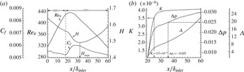
(a) Streamwise variation of
 $\mathit{Re}_{{\it\theta}}$
,
 $C_{f}$
and
 $H$
and (b) parameters
 $K$
,
 ${\rm\Delta}p$
and
 ${\it\Lambda}$
.

3. Discussion of results
Figure 2(a) shows streamwise developments of the Reynolds number
 $\mathit{Re}_{{\it\theta}}=U_{\infty }{\it\theta}/{\it\nu}$
(where
 ${\it\theta}$
is the momentum thickness), the shape factor
 $H={\it\delta}^{\ast }/{\it\theta}$
(where
 ${\it\delta}^{\ast }$
is the displacement thickness) and the skin friction coefficient
 $C_{f}=2{\it\tau}_{w}/{\it\rho}U_{\infty }^{2}$
. The value of
 $\mathit{Re}_{{\it\theta}}$
changes almost linearly not only in the ZPG region (increasing) but also in the FPG region (decreasing), the maximum nearly coinciding with the maximum slope of
 $C_{f}$
at the ZPG–FPG intersection. If we take
 $x/{\it\delta}_{inlet}\simeq 24$
to be the onset of relaminarization (inferred from
 $\mathit{Re}_{{\it\theta}}$
and
 $C_{f}$
changes), it is clear that the shape factor
 $H$
is a poor indicator of the start of change in the flow state – which is not surprising, as it is a ratio of two integral measures of the mean profile. Additionally, some of the indicators of the onset of relaminarization described in § 1 are also plotted in figure 2(b). The acceleration parameter
 $K$
rises abruptly at the ZPG–FPG intersection (
 $18\leqslant x/{\it\delta}_{inlet}\leqslant 26$
) to finally asymptote to the constant value of
 $4.0\times 10^{-6}$
, beginning at
 $x/{\it\delta}_{inlet}\approx 30$
. Based on Spalart (Reference Spalart1986), the present flow should have been relaminarized (since
 $K>3.0\times 10^{-6}$
); however, notice that
 $C_{f}$
never achieves the laminar value for sink flows (i.e.
 $C_{f}=2.31\sqrt{K}=0.00462$
according to Rosenhead (Reference Rosenhead1963)), indicating that the relaminarization process is not complete. The critical
 $K$
value of
 $3.5\times 10^{-6}$
suggested by Kline et al. (Reference Kline, Reynolds, Schraub and Runstadler1967) was achieved around
 $x/{\it\delta}_{inlet}\approx 25$
. Furthermore, the critical value of −0.025 for
 ${\rm\Delta}p$
(Patel Reference Patel1965) was reached at
 $x/{\it\delta}_{inlet}\approx 35.5$
. Nevertheless, the maximum computed value of
 ${\it\Lambda}$
(
 ${\sim}22$
) is lower than the laminarization indicator of
 ${\it\Lambda}_{c}=50$
proposed by Narasimha & Sreenivasan (Reference Narasimha and Sreenivasan1973). Consequently, previous indicators of the relaminarization onset
 $K$
and
 ${\rm\Delta}p$
have predicted relaminarization in our FPG region, except the
 ${\it\Lambda}$
parameter by Narasimha & Sreenivasan (Reference Narasimha and Sreenivasan1973). Thus, in order to shed some light on the actual flow state in the FPG region, we evaluate the contributions of the different terms in the
 $x$
component of the Navier–Stokes equation:
 $$\begin{eqnarray}\underbrace{U\frac{\partial U}{\partial x}}_{Ia}+\underbrace{V\frac{\partial U}{\partial y}}_{IIa}=\underbrace{-\frac{1}{{\it\rho}}\frac{\text{d}P_{\infty }}{\text{d}x}}_{IIIa}+\underbrace{{\it\nu}\frac{\partial ^{2}U}{\partial y^{2}}}_{IVa}-\underbrace{\frac{\partial \overline{u^{\prime }v^{\prime }}}{\partial y}}_{Va}.\end{eqnarray}$$
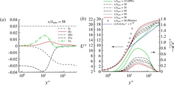
Instead of the typical inner and outer equations (Tennekes & Lumley Reference Tennekes and Lumley1972) for the TBL with pressure gradient, we have now a single equation for the entire boundary layer. Figure 3(a) depicts the terms of (3.1) in wall units in the FPG region at
 $x/{\it\delta}_{inlet}=58$
where
 ${\it\delta}^{+}=239$
. The following key aspects are noted: (i) a laminar sub-boundary layer is observed only for
 $y^{+}<3$
, where terms
 $IIIa$
and
 $IVa$
balance each other; (ii) in accelerated flows, the viscous and inertia terms are
 $O(1)$
even in the viscous region; (iii) the ratio of peaks of the turbulent transport term (
 $Va$
) to the viscous transport term (
 $IVa$
) (located at
 $y^{+}\approx 10$
) is approximately 0.4, whereas this value was calculated as 1 in the ZPG zone at
 $y^{+}\approx 7$
(not shown); and (iv) in the outer region for
 $y^{+}\geqslant 50$
, terms
 $Ia$
and
 $IIIa$
are in balance while term
 $IIa\rightarrow 0$
(i.e. inviscid region). Consequently, the turbulent transport is not negligible with respect to the viscous contribution in the region
 $3\leqslant y^{+}<50$
and hence the present flow is neither fully turbulent nor fully laminar. Furthermore, since the ratio of the turbulent transport term to the pressure gradient term in figure 3(a) (around 0.53 at
 $y^{+}\approx 12$
) is significant, present FPG flow cannot be described by the dual-layer approach of Narasimha & Sreenivasan (Reference Narasimha and Sreenivasan1973), and hence does not follow their soft relaminarization category. More specifically, our strong FPG flow might be situated within the ‘laminarescent’ region (b) of Sreenivasan (Reference Sreenivasan1982), just upstream of the relaminarization onset, which is consistent with computed values of
 ${\it\Lambda}$
lower than 50. Note that the focus of the present study is the log behaviour of Reynolds shear stress subjected to strong FPG; of course, it is important to assess the present flow state. Analysing the different stages of relaminarization is beyond the scope of present study.
(a) Terms of (3.1) at
 $x/{\it\delta}_{inlet}=58$
and (b) mean streamwise velocity and Reynolds shear stresses.

Figure 3(b) shows evolutions of the mean streamwise velocity and the
 $\overline{u^{\prime }v^{\prime }}^{+}$
profiles. In addition, the logarithmic (
 $2.5\ln y^{+}+5.0$
) and Blasius profiles (by matching
 ${\it\delta}$
at
 $x/{\it\delta}_{inlet}=58$
) are included. Firstly, the profiles in the FPG region with constant
 $K$
significantly depart from the ‘universal’ log-law behaviour (i.e.
 ${\it\kappa}=0.40$
and
 $B=5.0$
(Tennekes & Lumley Reference Tennekes and Lumley1972)) also found by Piomelli & Yuan (Reference Piomelli and Yuan2013). Parenthetically, even in the ZPG zone, the
 $U^{+}$
profile does not follow the ‘universal’ log law (note that the ZPG and log-law profiles are shifted downwards by 2 units for clarity). Secondly, the profiles do not follow the Blasius solution. Thirdly, the wake region disappears in the FPG region. Apart from dropping abruptly at the start of the FPG region,
 $\overline{u^{\prime }v^{\prime }}^{+}$
shows a clear log behaviour for
 $50\leqslant y^{+}\leqslant 170$
. To our knowledge, such a trend in highly accelerated flows has never been reported.
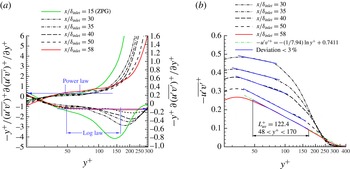
Similar to
 $U^{+}$
, one could write a diagnostic function for
 $\overline{u^{\prime }v^{\prime }}^{+}$
for the log law and the power law as shown in figure 4(a). Notice the power-law behaviour in the ZPG profile (e.g. in the region
 $48\leqslant y^{+}\leqslant 66$
) as well as in profiles at the beginning of the FPG region. Particularly, for the ZPG profile at
 $x/{\it\delta}_{inlet}=15$
, the power is
 ${\it\gamma}_{uv}\simeq 0.35$
. The power law for ZPG is striking whereas the diagnostic function clearly shows that
 $\overline{u^{\prime }v^{\prime }}^{+}$
in ZPG is not logarithmic. However, the power-law length in the ZPG profile is around 18 wall units and occupies only 10 % of the local boundary layer thickness. Interestingly, the log tendency in
 $\overline{u^{\prime }v^{\prime }}^{+}$
(right axis) is more pronounced than the power-law region, as the acceleration parameter
 $K$
asymptotes to the value of
 $4.0\times 10^{-6}$
. The diagnostic function for
 $\overline{u^{\prime }v^{\prime }}^{+}$
depicts almost constant values (
 ${\approx}-0.125$
) in the region
 $50\leqslant y^{+}\leqslant 170$
(i.e. mesolayer as defined in George & Castillo (Reference George and Castillo1997)) at
 $x/{\it\delta}_{inlet}=58$
with a log coefficient
 $A_{uv}\approx 7.94$
. Therefore, it can be inferred that the logarithmic behaviour in
 $\overline{u^{\prime }v^{\prime }}^{+}$
is a unique feature of strongly accelerated flows. Nevertheless, a much shorter but non-negligible power-law region was observed in ZPG and at the beginning of the FPG regime. This log region is evident in figure 4(b), where
 $\overline{u^{\prime }v^{\prime }}^{+}$
profiles for various streamwise locations in the FPG region are shown for the present DNS. Note the log curve-fitting function at
 $x/{\it\delta}_{inlet}=58$
(i.e.
 $-\overline{u^{\prime }v^{\prime }}^{+}=-(1/7.94)\ln y^{+}+0.7411$
in light grey dot-dashed; green online) and the corresponding length,
 $L_{uv}^{+}$
, of the log region (computed by considering less than 3 % deviation, as in all cases in this paper), which extends approximately from
 $y^{+}\approx 50$
to 170 at this streamwise location. Highlighted in dark grey (blue online), the log regions for the other
 $x$
locations are shown. The starting point locations of these log regions are approximately the same, within
 $y^{+}\approx 30{-}50$
(or
 $y/{\it\delta}\approx 0.13{-}0.2$
, not shown). Nevertheless, notice that the log regions increase along the FPG zone and the corresponding slopes tend to a constant value for
 $x/{\it\delta}_{inlet}\geqslant 50$
.
(a) Diagnostic functions for the log-law and power-law behaviours of
 $\overline{u^{\prime }v^{\prime }}^{+}$
, and (b) profiles of
 $\overline{u^{\prime }v^{\prime }}^{+}$
in the FPG region (present DNS).

Figure 5(a) depicts the
 $\overline{u^{\prime }v^{\prime }}^{+}$
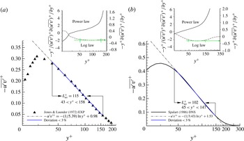
profile and its log-law and power-law diagnostic functions (insets) from the experiments of Jones & Launder (Reference Jones and Launder1972) in sink-flow TBL at
 $\mathit{Re}_{{\it\theta}}=303$
and
 $K=2.96\times 10^{-6}$
(at
 $x=24~\text{in.}$
). Reynolds shear stresses were obtained from the measured mean velocity profiles, by transforming and integrating a boundary layer equation for flow between converging planes (see expression (1) in Jones & Launder Reference Jones and Launder1972). In figure 5(a),
 $\overline{u^{\prime }v^{\prime }}^{+}$
is clearly described by a logarithmic curve for
 $43<y^{+}<158$
. This log region,
 $L_{uv}^{+}$
, occupies a significant portion of the boundary layer (
 $L_{uv}^{+}/{\it\delta}^{+}\approx 0.7$
). Similarly, the DNS from Spalart (Reference Spalart1986) in sink flows with
 $\mathit{Re}_{{\it\theta}}=380$
and
 $K=2.75\times 10^{-6}$
is shown in figure 5(b). It can be seen that the log region extends over
 $45<y^{+}<147$
(as in Jones & Launder Reference Jones and Launder1972), with the ratio
 $L_{uv}^{+}/{\it\delta}^{+}\approx 0.46$
. Moreover, the diagnostic function shows a non-existent power law, a unique feature of sink flows. Curiously, the
 $K$
parameters in Jones & Launder (Reference Jones and Launder1972) and Spalart (Reference Spalart1986) are within their proposed threshold values to predict relaminarization, yet the
 $\overline{u^{\prime }v^{\prime }}^{+}$
profiles show a log behaviour. The present results indicate that the logarithmic behaviour of
 $\overline{u^{\prime }v^{\prime }}^{+}$
is due to strong FPG in both sink and other spatially developing flows.
Profiles of
 $\overline{u^{\prime }v^{\prime }}^{+}$
and diagnostic functions for power and log laws in sink flows: (a) experiments from Jones & Launder (Reference Jones and Launder1972) and (b) DNS from Spalart (Reference Spalart1986).

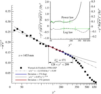
In addition, experiments from Warnack & Fernholz (Reference Warnack and Fernholz1998) with local values of
 $K=4.0\times 10^{-6}$
and
 $\mathit{Re}_{{\it\theta}}\approx 560$
(figure 6) also exhibit a log region for
 $\overline{u^{\prime }v^{\prime }}^{+}$
with
 $L_{uv}^{+}\approx 171$
and
 $L_{uv}^{+}/{\it\delta}^{+}\approx 0.35$
. The log region can be extended up to
 $y^{+}\simeq 50$
, but the scatter in the measurements near the wall calls for some precaution. The inset in figure 6 shows clear evidence of a log region, whereas the power-law region is shorter but not negligible. The computed length was around 85 wall units based on the power-law curve fitting, approximately 17 % of the local
 ${\it\delta}^{+}$
. In Warnack & Fernholz (Reference Warnack and Fernholz1998),
 $K$
was not constant; on the contrary, increasing
 $K$
up to a local maximum followed by re-transition was imposed (i.e. spatially developing FPG flow).
Profiles of
 $\overline{u^{\prime }v^{\prime }}^{+}$
and diagnostic functions for power and log laws in other spatially developing FPG flows; experiments from Warnack & Fernholz (Reference Warnack and Fernholz1998).

Hence, some important observations can be made so far: (i) the logarithmic behaviour of
 $\overline{u^{\prime }v^{\prime }}^{+}$
is due to the strong FPG, which significantly enhances the inertial terms, particularly in the inner region; (ii) longer log regions of
 $\overline{u^{\prime }v^{\prime }}^{+}$
(i.e.
 $L_{uv}^{+}/{\it\delta}^{+}\approx 0.46{-}0.7$
) have been observed in sink flows, but no power law; (iii) smaller log regions of
 $\overline{u^{\prime }v^{\prime }}^{+}$
in other spatially developing FPG flows (i.e.
 $L_{uv}^{+}/{\it\delta}^{+}\approx 0.35$
as in Warnack & Fernholz (Reference Warnack and Fernholz1998)) have also been found; and (iv) a shorter but non-negligible power-law trend of
 $\overline{u^{\prime }v^{\prime }}^{+}$
in other spatially developing FPG flows has been observed. The last is consistent with the present DNS; the power-law trend of
 $\overline{u^{\prime }v^{\prime }}^{+}$
in figure 4(a) vanishes as
 $K$
grows asymptotically towards a constant value (i.e.
 $4.0\times 10^{-6}$
), resembling a sink flow.
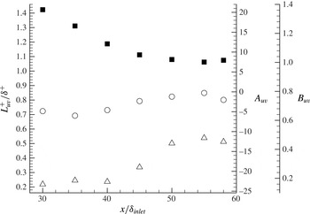
The length of the log region
 $L_{uv}^{+}/{\it\delta}^{+}$
depicted in figure 7 increases almost exponentially for
 $x/{\it\delta}_{inlet}\geqslant 32$
(which corresponds to
 $H_{min}$
). Moreover, the log coefficients
 $A_{uv}$
and
 $B_{uv}$
in figure 7 exhibit a weak linear dependence on
 $x$
. Note that these coefficients are not universal but depend on
 $K$
and Reynolds number, i.e.
 $A_{uv}=A_{uv}(K;{\it\delta}^{+})$
,
 $B_{uv}=B_{uv}(K;{\it\delta}^{+})$
and
 $L_{uv}^{+}=L_{uv}(K;{\it\delta}^{+})$
.
Streamwise development of the logarithmic coefficients
 $A_{uv}$
(▪) and
 $B_{uv}$
(○) and length
 $L_{uv}^{+}/{\it\delta}^{+}$
(▵).

By integrating in
 $y$
the
 $x$
component of the Navier–Stokes equation (3.1), we evaluate each term:
 $$\begin{eqnarray}\displaystyle \overline{u^{\prime }v^{\prime }}^{+} & = & \displaystyle -\underbrace{\int _{0}^{y^{+}}\!U^{+}\frac{\partial U^{+}}{\partial x^{+}}\,\text{d}y^{+}}_{I}-\underbrace{\int _{0}^{y^{+}}\!V^{+}\frac{\partial U^{+}}{\partial y^{+}}\,\text{d}y^{+}}_{II}-\underbrace{\frac{\text{d}P_{\infty }^{+}}{\text{d}x^{+}}y^{+}}_{III}+\underbrace{\frac{\partial U^{+}}{\partial y^{+}}}_{IV}-1\nonumber\\ \displaystyle & & \displaystyle +\,\underbrace{\int _{0}^{y^{+}}\!\frac{\partial \overline{v^{\prime 2}}^{+}}{\partial x^{+}}\,\text{d}y^{+}}_{VI}-\underbrace{\int _{0}^{y^{+}}\!\frac{\partial \overline{u^{\prime 2}}^{+}}{\partial x^{+}}\,\text{d}y^{+}}_{VII}.\end{eqnarray}$$
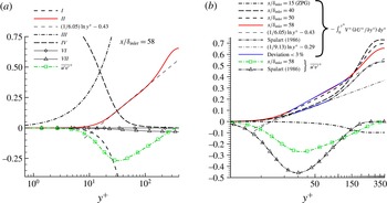
Figure 8(a) depicts each term in (3.2) at
 $x/{\it\delta}_{inlet}=58$
. Several major observations can be made: (i) the streamwise and wall-normal components of advection (terms
 $I$
and
 $II$
, respectively) are both significant in the viscous region (i.e.
 $O(1)$
); (ii) the pressure gradient (term
 $III$
) is dominant in the entire boundary layer; (iii) as expected, contributions from terms
 $VI$
and
 $VII$
are negligible; and (iv) interestingly, the integral of the wall-normal advection (term
 $II$
) exhibits a clear logarithmic trend in the mesolayer region (
 $30\leqslant y^{+}\leqslant 170$
), as also observed in
 $\overline{u^{\prime }v^{\prime }}^{+}$
. The log nature of term
 $II$
in the FPG zone is evident in figure 8(b) for various streamwise locations. Term
 $II$
in the ZPG region (
 $x/{\it\delta}_{inlet}=15$
) is negligible and negative (owing to the positive values of
 $V^{+}$
in the entire boundary layer). There is a slight increase of the term
 $II$
in ZPG from
 $y^{+}\approx 200$
, at the boundary layer edge where
 $V^{+}$
is maximum. Furthermore, the FPG profiles of term
 $II$
show a steep increase from
 $y^{+}\approx 20$
with a longer log region as the flow moves downstream. This log behaviour in term
 $II$
is also observed in the DNS sink-flow data from Spalart (Reference Spalart1986) as shown in figure 8(b).
(a) The
 $x$
-momentum balance at
 $x/{\it\delta}_{inlet}=58$
and (b) behaviour of the inertia term,
 $-V^{+}\,\partial U^{+}/\partial y^{+}$
and
 $\overline{u^{\prime }v^{\prime }}^{+}$
in wall units.

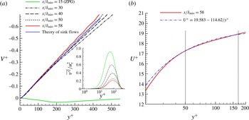
Figure 9(a) exhibits the mean vertical velocity,
 $V^{+}$
, and the wall-normal component of Reynolds normal stress,
 $\overline{v^{\prime 2}}^{+}$
, at various streamwise locations. Notice the significant increases of
 $V^{+}$
in the FPG region compared to the ZPG values. On the contrary, the
 $\overline{v^{\prime 2}}^{+}$
profiles depict substantial reductions downstream of the FPG region. From the sink-flow theory of Spalart (Reference Spalart1986), it can be demonstrated that
 $V^{+}(x^{+},y^{+})=-[y^{+}/R^{+}]U(x^{+},y^{+})$
, where
 $R^{+}$
is the sink point distance in wall units. Hence, the mean vertical velocity is proportional to the mean streamwise velocity. However, the dependence of
 $V^{+}$
on
 $U^{+}$
is extremely weak since
 $R^{+}$
is very large (
 $R^{+}\sim 13\,000$
in the present DNS). Therefore, the mean vertical velocity can be expressed as
 $V^{+}=-[U^{+}/R^{+}]y^{+}$
, resulting in
 $V^{+}\sim -y^{+}$
. Notice the good agreement of the
 $V^{+}$
profile from the present DNS with that from the sink-flow theory at
 $x/{\it\delta}_{inlet}=58$
in figure 9(a). Furthermore, the term
 $Va$
in (3.1) can be expressed as
 $-\partial (\overline{u^{\prime }v^{\prime }}^{+})/\partial y^{+}=\overline{v^{\prime }{{\it\omega}_{z}}^{\prime }}^{+}-\overline{w^{\prime }{{\it\omega}_{y}}^{\prime }}^{+}=F_{net}\,(\text{net force})=F_{1_{x}}-F_{2_{x}}$
. The second term originates from the Lamb vector in the Navier–Stokes equation and represents the ‘vortex’ force (Tennekes & Lumley Reference Tennekes and Lumley1972). It can be shown that only
 $\overline{v^{\prime }\,\partial u^{\prime }/\partial y}$
is the dominant term from
 $F_{net}$
. In addition, it was found that
 $V^{+}\,\partial U^{+}/\partial y^{+}\sim \partial \overline{u^{\prime }v^{\prime }}^{+}/\partial y^{+}\sim 1/y^{+}$
in the mesolayer, which obviously yields a logarithmic profile for
 $\overline{u^{\prime }v^{\prime }}^{+}$
; and thus
 $V^{+}\,\partial U^{+}/\partial y^{+}\sim \overline{v^{\prime }\,\partial u^{\prime }/\partial y}$
. Consequently, the log behaviour of
 $\overline{u^{\prime }v^{\prime }}^{+}$
coincides with the log behaviour of the wall-normal transport of mean momentum. Since
 $V^{+}\sim -y^{+}$
and
 $V^{+}\,\partial U^{+}/\partial y^{+}\sim 1/y^{+}$
, then
 $U^{+}=a+b/y^{+}$
, yielding a power law for
 $U^{+}$
. Figure 9(b) depicts a power-law curve fitting by the least-squares method in the range
 $50\leqslant y^{+}\leqslant 170$
(i.e. where
 $\overline{u^{\prime }v^{\prime }}^{+}$
exhibits a log trend) for
 $U^{+}$
at
 $x/{\it\delta}_{inlet}=58$
. It is observed in figure 9(b) that
 $U^{+}$
can reasonably be described by a power law in the mesolayer with constants
 $a=19.58$
and
 $b=-114.62$
at this streamwise location.
(a) Mean vertical velocity and wall-normal component of Reynolds normal stresses (inset) and (b) mean streamwise velocity and power-law curve fitting at
 $x/{\it\delta}_{inlet}=58$
.

4. Conclusions
DNS of accelerated TBL has shown a logarithmic behaviour of the Reynolds shear stress in the mesolayer region (e.g.
 $50\leqslant y^{+}\leqslant 170$
). The
 $\overline{u^{\prime }v^{\prime }}^{+}$
log-layer thickness extends through a large portion of the boundary layer thickness (up to 55 %). The log region in Reynolds shear stresses can be associated with the wall-normal advection, i.e.
 $V^{+}\,\partial U^{+}/\partial y^{+}\sim 1/y^{+}$
(
 ${\sim}\partial \overline{u^{\prime }v^{\prime }}^{+}/\partial y^{+}$
) in the inner layer. The mean vertical velocity is nearly linear and no longer negligible, as in ZPG boundary layers. As a consequence, the mean streamwise velocity can be represented by a power law of the form
 $U^{+}=a+b/y^{+}$
. The log behaviour of
 $\overline{u^{\prime }v^{\prime }}^{+}$
is evident in other experimental/numerical data of accelerated flows. The log region of
 $\overline{u^{\prime }v^{\prime }}^{+}$
is longer in sink than in other spatially developing FPG flows, with a small power-law region in the latter ones.
Acknowledgements
The authors acknowledge Dr P. Spalart for sharing his DNS data with us. G.A. acknowledges Professor K. Jansen for his important insight to this work and for supplying us with the flow solver PHASTA. Computational resources were supplied by XSEDE (project number: TG-CTS120046) and SCOREC (Scientific Computation Research Center) from Rensselaer Polytechnic Institute. L.C. would like to thank Dr M. Tutkun for his valuable comments on the manuscript.