I. INTRODUCTION
The necessity of high data-rate in the modern wireless communication devices has motivated the Federal Commission of Communication (FCC) to authorize the use of the 3.1–10.6 GHz spectrum band for the ultra-wideband (UWB) applications [1]. This event has been followed by many academic and industrial investigations realized in order to enhance the impedance bandwidth of small antennas, to be suitable for this new kind of applications. In the literature, there are mainly three categories of the UWB antennas. First, the vertical monopole antennas have been proposed with various shapes, such as square, circle, triangular, and trapezoid plates [Reference Chen, Ammann, Qing, Wu, See and Cat2]. Second, printed monopole antennas have been designed with different excitation mechanisms such as microstrip [Reference Liu, Lau and Chan3] and coplanar waveguide (CPW) [Reference Chair, Kishk and Lee4]. Third, the dielectric resonator antennas (DRAs) have been reported with various configurations [Reference Ahmed, Sebak and Denidni5–Reference Messaoudene, Benghalia, Boughendjour and Adjaoud9], such as a half cylindrical DRA, an A-shaped resonator, an inserted DRA excited by CPW, a conical-shape dielectric resonator (DR) with monopole antenna, and a stacked rectangular DRA.
In printed antennas, the CPW-fed antenna has many attractive features, such as low radiation loss, easy integration with RF Monolithic Microwave Integrated Circuits (MMIC) and etching on only one side of the substrate providing a simplified configuration [Reference Gautam, Yadav and Kanaujia10], comparing with microstrip-fed antennas.
Nowadays, some research groups have been focused their work in the incorporation of both UWB and narrow band antennas into a limited space. In this design, more challenge has been focused on a key issue related to efficient integration for ensuring good isolation between the two antenna ports [Reference Kelly, Song, Hall and Borja11–Reference Messaoudene, Denidni and Benghalia15]. According to the FCC, the omni-directional UWB antenna is used for dynamic spectrum sensing while the directional narrow-band element is used for transmission. This kind of structure was mainly reported for radar, medical imaging, cognitive radio (CR) applications, and weapon detection systems.
In this letter, we propose a new CPW-fed antenna structure containing two ports: Port1 excites the UWB patch antenna which will be used for sensing the spectrum, and Port2 excites the rectangular DR that will be used for communication. Comparing with existing designs, the proposed hybrid structure (patch/DRA) exhibits low mutual coupling, S 12 < −20 dB, between the two antenna ports. Moreover, the use of the CPW line to excite the DRA provides two operational bands, an improved gain, high radiation efficiency and broadside radiation patterns for the narrow band antenna. In the following sections, the antenna design and results are presented.
II. ANTENNA CONFIGURATION
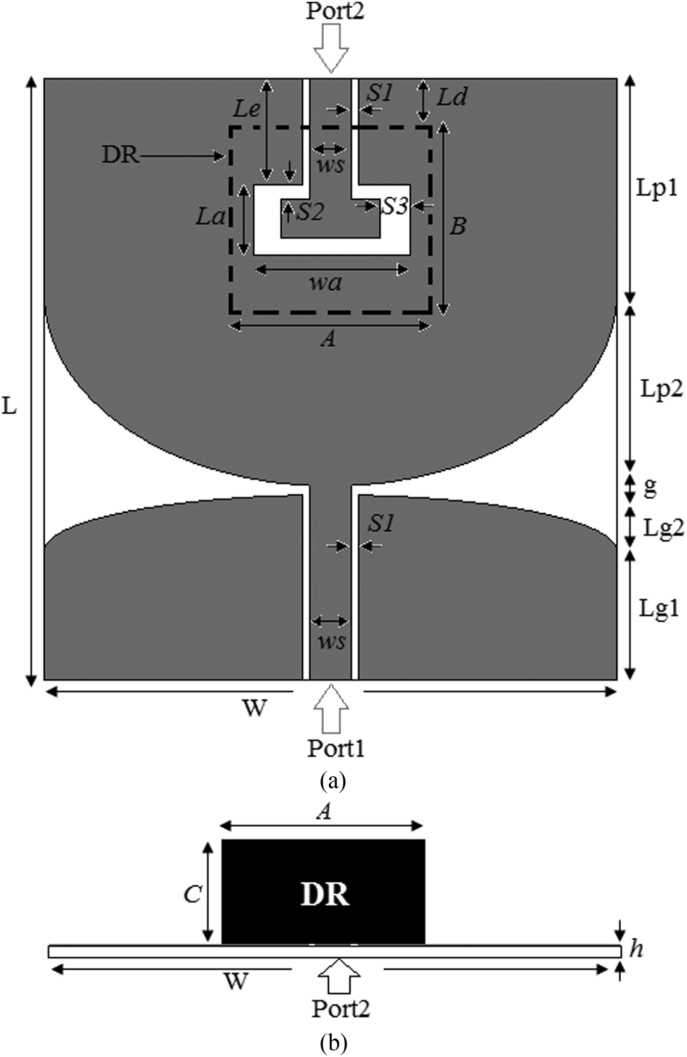
Figure 1 shows the geometry of the antenna structure under consideration. The proposed concept comprised of two parts: an UWB antenna integrated with a narrow-band antenna. The wideband antenna composed of CPW-fed rectangular monopole, with semi-elliptical base, printed on one side of 42 × 40 mm2 Rogers TMM6 substrate with a relative permittivity ε rs = 6, loss tangent of 0.0023, and thickness h = 0.762.
Geometry of the proposed structure; (a) top view and (b) side view.

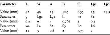
On the front of the substrate, a narrow band antenna (NB) is integrated to satisfy the requirement for combined wideband/narrow-band antennas. The NB antenna consists of 13 × 12.5 × 6.35 mm3 rectangular DR, with a relative permittivity ε rd = 9.8 (TMM10i), mounted on the patch antenna and excited from Port2 via a short section of CPW transmission line, as illustrated in Fig. 1. Table 1 summarizes the optimal parameters of the structure described in Fig. 1.
Optimal dimensions of the proposed design.
In order to study the principle of the isolation and the electromagnetic radiation, the surface current distribution analysis is used. In Figs 2(a), 2(b), and 2(c), the simulated magnitude surface current on the UWB antenna, without integrating the DR, is plotted at 3.5, 6, and 10 GHz, respectively. Form this figure, it can be seen that the tapered surface regions on the two sides of the antenna contain high current excitations, which explains their contribution to the radiation. In the other hand, the surface current density on the other extremity of the patch antenna is very low. This area can be exploited to integrate a DRA.
Surface current distributions on the UWBA without integrating DRA at (a) 3.5 GHz, (b) 6 GHz, and (c) 10 GHz.
In addition, this analysis technique is used, after the integration of the dual-band antenna, to evaluate the mutual coupling between the two ports. Figure 3 shows the plots of the current density on the integrated antenna excited separately from the port P1 and port P2, at two frequencies 5.8 and 9.1 GHz. As illustrated in Fig. 3, the surface current density on both the UWB antenna and the integrated DR antenna, when port P1 is excited and port P2 is terminated with 50 Ω and vice versa, is very low, which allows an efficient integration with good isolation.
Surface current distributions on the integrated UWB/DR antenna at (a) 5.8 GHz and (b) 9.1 GHz.
III. SIMULATED AND MEASURED RESULTS
To examine the performance of the proposed antenna, numerical simulations were carried out with two software tools: CST Microwave Studio and Ansoft HFSS. Then, the proposed design has been optimized. Furthermore, for experimental validation, a prototype of the proposed antenna was fabricated. Figure 4 shows a photograph of the fabricated antenna. Then, the measurements were carried out using Agilent 8722ES network analyzer and an anechoic chamber for S-parameter and radiation pattern measurements, respectively.
Photograph of fabricated prototype antenna.
Figure 5 shows the measured and simulated return loss (S 11) of the proposed structure excited through Port1. From the measured results, it can be seen that the patch antenna offers 2:1 VSWR band from 2.44 to 11.9 GHz, which largely covers the UWB spectrum band (3.1–10.6 GHz). The CST and HFSS simulated results show that the monopole antenna provides an impedance bandwidth of 2.4–12 GHz and 2.05–12 GHz, respectively.
Reflection coefficient of the UWB antenna S 11 (excited from Port1).
Both simulated and measured return losses (S 22) of the rectangular DRA are plotted together in Fig. 6. It is clear from the measurements that the use of CPW transmission line for the DRA mechanism excitation achieved two different operational bands: 5.3–6.2 GHz (for wireless local area network communications; High Performance Local Area Network HIPERLAN/2 and IEEE 802.11a applications) and 8.5–9.4 GHz (suitable for military applications). In addition, the dual-band antenna provides two bandwidths of 500 MHz (5.7–6.2 GHz) and 900 MHz (8.7–9.6 GHz) for CST, when the HFSS simulation gives 501 MHz (5.69–6.2 GHz) and 1.5 GHz (8.7–9.6 GHz). Furthermore, the DRA can be tuned using an external matching circuit like in the reference [Reference Desjardins, McNamara, Thirakoune and Petosa16], to be suitable for CR applications. The proposed dual-band antenna can be scanned the whole UWB spectrum by tuning the half spectrum band.
Reflection coefficient of the DR antenna S 22 (excited from Port2).
Figure 7 shows the mutual coupling between the two antenna ports. It is presented in terms of transmission coefficient (S 12/21). From this figure, it can be observed that the proposed concept ensures good isolation between the UWB and DR antennas (with S 12/21 less than −20 dB in the whole operating frequency band), which guarantees an efficient integration. There is a reasonable agreement between the simulated and measured S-parameters. However, the small discrepancy is mainly caused by the fabrication error and the RF cable of the network analyzer, which slightly affects the measurements of small antennas.
Transmission coefficient of the proposed structure (S 12/21).
To study the radiation characteristics of the proposed antenna, the radiation patterns were measured inside an anechoic chamber. Then, the measured and computed far field radiation patterns of the proposed design, in the two main planes (E-plane and H-plane), are plotted and compared in Figs 8 and 9.
Measured and simulated radiation patterns of the wideband antenna at; (a) 3.5 GHz, (b) 6.5 GHz, and (c) 10 GHz; dark solid lines for measurement and light dashed lines for computation.
Measured and simulated radiation patterns of the DRA at; (a) 5.8 GHz and (b) 9.1 GHz; dark solid lines for measurement and light dashed lines for computation.
Figure 8 presents the radiation pattern of the UWB antenna at three sampled frequencies (3.5, 6.5, and 10 GHz). It can be seen that the wide-band antenna exhibits stable radiation patterns in the full operational band, with a nearly omni-directional radiation characteristic in the H-plane and bi-directional in the E-plane, suitable for UWB radiation pattern requirements. Furthermore, the measured radiation characteristics of the rectangular DRA, at its two resonant frequencies (5.8 and 9.1 GHz), are compared with those of simulation in Fig. 9. It is noted that the dual-band antenna provides a broadside radiation patterns in the two planes. A good agreement have is achieved between the simulated and measured radiation patterns.
The calculated and measured realized gains of the wideband and dual-band antennas are presented in Fig. 10. It is found that the UWB antenna gain ranges between 2 and 4.4 dB, and the DRA provides 6.6 and 5.2 dB of gain around its resonant frequencies.
Measured and simulated realized gain of the proposed antenna design.
Table 2 reports the radiation efficiency of both ultra-wide band and dual-band antenna at five selected frequencies. It can be seen that the patch antenna achieves an average efficiency of 75.1%, and the DR antenna provides between 95.4 and 97.9% radiation efficiency at its two operated frequencies.
Radiation efficiency at selected frequencies.

IV. CONCLUSION
A new UWB antenna integrated with dual-band DRA has been designed and fabricated. The patch monopole antenna provides an impedance bandwidth from 2.44 to 11.9 GHz, and covering the whole UWB spectrum band, and the CPW-fed rectangular DRA operates around two different frequency bands at 5.8 and 9.1 GHz, which can be used for communication. In addition, the proposed hybrid design exhibits low mutual coupling between the two antenna ports in the full operational band (with transmission coefficient less than −20 dB), which permits an efficient integration. The simulated and measured results have shown a good agreement. With these characteristics, the proposed concept can be a suitable candidate for radar, medical imaging, cognitive-radio, and weapon systems.
 Idris Messaoudene was born in Bordj Bou Arréridj, Algeria in 1986. He received his Ph.D. degree in Microwaves and Telecommunications from the University of Constantine 1, in 2014, and his Master's degree in Networks and Telecommunication Technologies from the University of Bordj Bou Arréridj Algeria, in 2009. His research interests include dielectric resonator antennas, printed antennas, UWB antennas, reconfigurable antennas, antennas for MIMO systems, and numerical methods for electromagnetism analysis.
 Tayeb A. Denidni received his M. Sc. and Ph.D. degrees in Electrical Engineering from Laval University, Quebec City, QC, Canada, in 1990 and 1994, respectively. From 1994 to 1996, he was an Assistant Professor with the engineering department, Université du Quebec in Rimouski (UQAR), Quebec, Canada. From 1996 to 2000, he was also an Associate Professor at UQAR, where he founded the Telecommunications laboratory. Since August 2000, he has been an Associate professor with Institut National de la Recherche Scientifique (INRS-EMT), Montreal, Canada. His current research interests include planar microstrip antennas, dielectric resonator antennas, electromagnetic-bandgap (EBG) antennas, antenna arrays, and microwave and RF design for wireless applications. He has authored over 100 papers in refereed journals. He has also authored or coauthored more than 200 technical presentations and invited talks in numerous national and international conferences and symposia.
 Abdelmadjid Benghalia was born in Sigus, Algeria. He received his Ingenieur degree in Electronics from the Ecole Nationale Polytechnique d'Alger, Algeria, and his Ph.D. degree from National polytechnic Institute of Toulouse (ENSEEIHT), France, in 1978 and 1989, respectively. Since 1980, he has been with l'Institut d'Electronique, Université de Constantine 1, Algeria as an Assistant Professor then as a Professor. He set up the initial nucleus of the Hyperfrequency and Semiconductor Laboratory (LHS) at the University of Constantine 1, in 2001. His research interests include microstrip antennas, dielectric resonator antennas, microstrip transmission lines, UWB antennas, numerical methods analysis, photonic crystals, the slow wave, and other related structures.