
I. INTRODUCTION
Titanium and its alloys have become key supporting materials in biomedical and aerospace industry due to their excellent comprehensive mechanical properties and the improvements made on machining these alloys. Reference Tan, Zhang, Yao, Wu and Zhang1,Reference Saoubi, Outeiro, Chandrasekaran, Dillon and Jawahir2 According to Ulutan and Tan, Reference Ulutan and Ozel3,Reference Tan and Yan4 a typical characteristic of the titanium alloy-machined surface consists mainly of three parts: the surface white layer, the subsurface plastic deformation zone, and bulk material. In previous studies, the surface white layer states that processed components have attracted substantial efforts in academic and in the application field. Reference Che-Haron5,Reference Sharman, Hughes and Ridgway6 However, with the increasing demands for machined precision and surface quality in the micro-machining process, it is important to recognize that the mechanical properties and lifetime of the workpiece are determined by no means only on the shape or on precision of the machined surface, and the characteristics of the subsurface microstructure may dominate the component’s service performance and reliability, as well. Reference Bushlya, Zhou and Stahl7 Specially, the change of the subsurface microstructure and the release of residual stress caused by powerful shearing action would result in inherent deformation and form the subsurface damage (SSD) layer underneath the surface. The presence of the damage layer can inevitably deteriorate the structural and functional performance of the finished components, such as weakening machined surface strength, affecting the application durability and secular stability of end parts. In this context, the evaluation of subsurface microstructure alteration and defects distribution would exhibit a critical role in optimizing machining parameters and processing efficiency.
Research showed that most of the major threats to the finished surface were derived from a workpiece subsurface microstructure evolution during the microcutting process. Reference Jawahir, Brinksmeier, Saoubi, Aspinwall, Outeiro, Meyer, Umbrello and Jayal8 Therefore, to further illuminate the formation and influence mechanisms of subsurface defects, lots of experimental and theoretical studies have been carried out. Ginting et al. Reference Ginting and Nouari9 focused on the processed subsurface quality in dry-cutting titanium alloy. Experimental observations concluded that in the subsurface area remarkable plastic deformation and microstructure alteration took place. Thomas et al. Reference Thomas, Turnerb and Jackson10 argued that the microstructural subsurface damages were detected in the form of intense slip bands after micro-milling of the titanium alloy. Such damages would degrade the in-service properties of the component because of a reduction in fatigue crack initiation resistance. Kwong et al. Reference Kwong, Axinte and Withers11 indicated that the subsurface damage layer may also result in a microcrack in the bulk material. In addition, during the microcutting process, it is known that the subsurface microstructure alteration is mainly influenced by a series of intrinsic and extrinsic parameters such as, processing parameters, tool structure, and material properties. Jin et al. Reference Jin and Liu12 stipulated that machining parameters played a vital role in the formation of the subsurface damage layer in orthogonal milling of FGH95 superalloy. Lv et al. Reference Lv, Wang, Zhang and Yin13 proposed a nontraditional technology to measure the thickness and distribution of the subsurface damage layer during rotary ultrasonic machining of the glass BK7 process. Results showed that the subsurface damage depth generated in cutting process was directly proportional to the increased cutting depth and feed speed of cutter tool. To et al. Reference Zhang, To, Cheung and Zhu14 presented experiments to reveal the influence of microstructural changes under various axial depths of cut on machined surface textures during micro-turning process. They found that the microstructure evolution simultaneously ensued and enhanced the uncertainty of surface topography relating to workpiece swelling, recovery and surface finish. Furthermore, after micro-cutting process, the defect structure of subsurface tends to store lots of micro-inner stress. Reference Bai, Bai, Tong, Hu and He15 Comparing with the residual stress, it always presents greater potential risks in terms of crack initiation, evolution and fatigue failure within end components. Reference Guo, Li and Jawahir16 However, although foregoing experimental data can reflect certain subsurface characteristics, it is worth pointing out that no predictive, experimental, or numerical work has ever been presented to quantitatively track the formation and propagation mechanism of workpiece subsurface damages.
Recently, an orthogonal cutting simulation has been exploited as a means for investigating the surface and subsurface microstructure alteration for various materials. Reference Gurusamy and Rao17 Shin et al. Reference Ding and Shin18 developed a finite element analysis framework to predict the machined chip and surface grain refinement process. However, a key limitation of their model is that the constitutive equation depends only on dislocation-based model d = Kρ0.5, where K is the material constant, d and ρ are the grain size and the dislocation density, respectively. It indicates that continuous changes can take place if the external load is enough to cause a net increase of total dislocation density. Not only that, the multiplication and evolution of dislocation in previous physically based modeling approaches were simple predicted as a function of strain, which cannot precisely factor in the interaction among dislocations, grain boundaries and crystal defects. Reference Hore, Das, Banerjee and Mukherjee19 According to molecular dynamics (MD) method, Wang et al. Reference Wang, Bai, Chen, Guo and Xie20 studied the stress-induced formation mechanism of subsurface stacking fault tetrahedra during the nano-cutting crystalline copper process. Li et al. Reference Li, Fang, Liu and Zhang21 analyzed the effect of various tool radii, crystal orientations and machining angles on subsurface deformation layer in nanoscale grinding. However, due to the limitation of analytical scale, the simple materials models and extreme cutting parameters resulted that the atomistic computer simulation not only cannot trace numerous subsurface defects interaction in complex cutting conditions, but would suppress the nucleation of subsurface dislocation. Particularly, as a typical mesoscale simulation way, discrete dislocation dynamics (DDD) could offer better scalability to conduct more intricate problems relative to MD way with larger time scale and space scale. Also, the DDD analytical method would provide better angle of vision into some aspects of material mechanical behaviors heretofore not uncovered by using continuum approaches, such as the transmutation of dislocation structure. Shishvan et al. Reference Shishvan and Van der Giessen22,Reference Shishvan and Van der Giessen23 showed that a simpler two-dimensional DDD study is more successful in revealing the microstructure evolution and plastic mechanism rather than the three-dimensional simulation. Tarleton et al. Reference Tarleton, Balint, Gong and Wilkinson24 revealed the microcantilever bending of hexagonal close-packed (HCP) structure crystals for a plane strain prismatic slip. Their study showed that the inhomogeneous and highly localized internal damage distribution would influence surface strengthening. Especially, on the basis of dislocation dynamics theory, the authors Reference Bai, Bai, Tong, Hu and He15 developed a new trans-scale cutting framework to reveal the refinement process of the surface grain structure in micro-machining Ti–6Al–4V. Results indicated that the predications of simulations were commensurate within the experimental scope. Thus, DDD can provide an effective way to reveal the subsurface microstructural changes and inner stress distribution during the micro-cutting process.
In present work, a series of discrete dislocation dynamics-based simulations were performed to qualitatively and quantitatively assert the distribution of the subsurface defect structure and its evolution during the orthogonal cutting process of titanium alloy under different cutting conditions, which for the first time considers both grain refinement and large-scale interaction among defects. Moreover, the influence of various processing parameters on subsurface microstructure alteration and inner stress field distribution were discussed. To this end, the article consists of the following key parts. Section II introduces the subsurface damage mechanism of titanium alloy. Section III provides a brief description about the trans-scale coupling algorithm. Section IV gives detailed simulation results and discussion. Section V summarizes the manuscript with some main conclusions.
II. SUBSURFACE DAMAGE OF TITANIUM ALLOY IN CUTTING PROCESS
Studies on titanium alloy showed that a damage layer can be found in the immediate subsurface deformation zone of the workpiece, and as the increment of tool wear, plastic deformation and subsequently the thickness of the damage layer increased due to subsurface microstructural alteration. Reference Che-Haron5,Reference Che-Haron and Jawaid25 Moreover, the depth of the damage layer beneath the finished surface was observed to change as the evolution of depth of the cut and feed rate and the increase of cutting speed from low level to high level would produce more serious grain refinement in the subsurface. Reference Ginting and Nouari9 However, some conflicting experimental results about the average depth of the subsurface damage layer from electron microscopy and electron backscattered diffraction (EBSD) were also found during the microcutting titanium alloy process, which have implications for the effectiveness of the current surface integrity research to determine the features of subsurface deformation for the finished titanium alloy. Reference Crawforth, Wynne, Turnerb and Jackson26
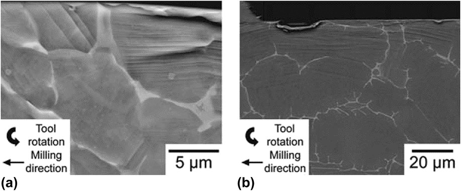
As the workpiece material is investigated in the present study, Ti–6Al–4V is composed of equiaxed alpha grains and a small quantity of intergranular beta phase. Reference Bermingham, McDonald, Dargusch and StJohn27 According to the EBSD results, Figs. 1(a) and 1(b) indicated the influence of the subsurface plastic strain imparted on Ti–6Al–4V and Ti-834 during the milling process. It is found that the subsurface damage layer is principally accommodated by dislocation evolution and slip bands within alpha phase grains. Reference Thomas, Turnerb and Jackson10 In particular, on the basis of Liu et al., Reference Wang, Liu, Wang, Song and Wan28 the effect of beta-titanium on subsurface plastic deformation can be ignored in the cutting simulation process due to the low volume fraction of the beta phase, which is not more than 8%. Thus, it is reasonable to assume that only alpha grains were considered in the present study and indicating that the subsurface zone was composed of HCP structural crystals. Moreover, it is noteworthy that the low stacking fault energy for the HCP crystal means that the transition of subsurface defect structure largely focusses on dislocation evolution rather than stacking faults. Reference Bai, Bai, Tong, Hu and He15,Reference Tarleton, Balint, Gong and Wilkinson24
Plastic deformation in the form of intense slip bands (a) Ti–6Al–4V and (b) Ti-834. Reference Thomas, Turnerb and Jackson10 [Reprinted with permission from Ref. Reference Thomas, Turnerb and Jackson10. M. Thomas, S. Turnerb, and M. Jackson: Microstructural damage during high-speed milling of titanium alloys. Scripta Mater 62, 250–253 (2010)].

III. DISLOCATION DYNAMICS-BASED SIMULATION FRAMEWORK FOR MICRO-CUTTING
A. Method of dislocation dynamics
In this work, a trans-scale coupling framework was performed by embedding discrete dislocation dynamics algorithm into a finite-element package via Python and Matlab scripting. This framework incorporated two characteristic scales: a nanometer scale and a continuum scale. For the former one, short-range phenomena, containing dislocation motion, junction, immobilization, interaction, and spatial rearrangement, were calculated by DDD simulation. In the continuum scale, finite element method (FEM) solver was used for a long-range solution of elastic driving stress of dislocations during micro-cutting process. As a typical line defect, the movement of dislocation is firmly controlled by Peach–Koehler (P–K) force, Reference Ouyang, Li, Huang and Hou29 which can be written as
 $$f_{\rm{g}}^{\left( I \right)} = \left( {\sigma + \sum\limits_{J \ne I} {\sigma _{ij}^{\left( J \right)}} } \right)b_j^{\left( I \right)}{m_i}\quad ,$$
 $$f_{\rm{c}}^{\left( I \right)} = - \left( {\sigma + \sum\limits_{J \ne I} {\sigma _{ij}^{\left( J \right)}} } \right)b_j^{\left( I \right)}{s_i}\quad ,$$
where σ
ij
denotes the internal stress field caused by other defects, σ denotes the external stress state on the glide plane,
 $f_{\rm{g}}^{\left( I \right)}$
denotes the slip force,
 $f_{\rm{c}}^{\left( I \right)}$
denotes the climb force,
 $b_j^{\left( I \right)}$
denotes the Burger’s vector of dislocation I, and {m
i
, s
i
} are unit normal and unit vector in the slip direction, respectively.
In DDD algorithm, the series of dislocation behaviors, such as dislocation nucleation and close encounters, must be governed by particular principles. Reference Ahmed and Hartmaier30 A mass of analogous Frank–Read (F–R) sources are randomly distributed throughout slip system, which possess intrinsic nucleation strength and nucleation time. A new nucleation event contains a pair of dislocations that can be generated in the form of dislocation dipoles. Similarly, the location of pre-existing obstacles is also on the basis of stochastic distribution on the glide planes. Specially, to reveal sufficiently the evolution process of the subsurface microstructure, a series of improvement constitutive rules are established to incorporate three-dimensional dislocation features into plane simulation, such as dislocation cross slip and dynamic junction formation, which may also act as potential points for F–R sources. Reference Benzerga, Brechet, Needleman and Van der Giessen31 In addition, the dislocation is allowed to move out of the original slip plane when its climb distance is larger than the magnitude of Burgers vector. Reference Davoudi, Nicola and Vlassak32,Reference Danas and Deshpande33 The mobile dislocations on intersectional slip planes would have locks if they are close enough together, which could form the new dislocation obstacles and impede subsequent dislocations. Moreover, opposite sign dislocations will be annihilated spontaneously when they come within a cut-off distance of 6b.
B. Modeling details
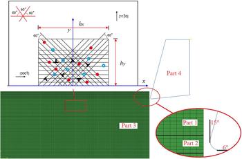
The trans-scale simulation model used in this article was shown in Fig. 2. The linear quadrilateral CPE4R planar strain element with enhanced hourglass control was chosen into temperature-displacement coupling analysis. To optimize the contact control during microcutting process, a multi-part FEM model was typically modeled. Reference Zhang, Mabrouki, Nelias and Gong34 The dimensions of the workpiece material were 30 × 12 μm. In this model, Part1 is the uncut chip thickness, Part 2 is the tool-tip surface contact zone, Part 3 is the material support zone, and Part 4 is the insert active cutting tool. In addition, a diamond tool was developed with a normal rake angle of 15° and a flank angle of 6°. The enter angle and inclination angle were 90° and 0°, respectively. The radius of the cutting edge was 0.25 μm. Then various cutting depths and cutting speeds were conducted to reveal the evolution mechanism of subsurface defects.
Trans-scale simulation model. The mesoscale material model consists of dislocation sources (solid circle), obstacle sources (open circle), pre-existing dislocations, slip system, grain boundary, and so on.

Abaqus with an explicit solver was adopted to improve the physical comprehension of the subsurface damage layer during orthogonal cutting of the titanium alloy. To capture the distribution of external applied stress of finite element (FE) nodes in the subsurface, fully coupled thermos-mechanical analysis was used within a time step of 0.5 ns. The boundary value problem of the subsurface support zone was solved in the FE module, which treated a mass of individual dislocations as the carriers of persistent subsurface plastic deformation.
Reference Bai, Bai, Tong, Hu and He15
Further, the image stress σNOD at the element node was calculated by subtracting the intrinsic stress produced by surrounding dislocations. Then, the elastic driving stress field of dislocation I could be obtained by linear interpolation algorithm. Finally, the computational results of each increment were constantly input to the DDD module, where the dislocation nucleation, accumulation, recovery, and annihilation were tracked.
Reference Huang and Li35
As shown in Fig. 2, a two-dimensional representative HCP cell model was built to explore the dislocation propagation rules in the support area. According to the previous study,
Reference Tarleton, Balint, Gong and Wilkinson24,Reference Crawforth, Wynne, Turnerb and Jackson26
discrete dislocation of titanium alloy moves in
 $\left\langle {11\bar{2}0} \right\rangle$
slip direction and on
 $\left\{ {10\bar{1}0} \right\}$
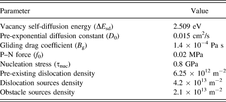
slip plane. Therefore, reference slip directions {0°, 60°, 120°} on the base of the x-axis were shown in Fig. 1(a). In addition, some detailed constants related to the present study were listed in Table I.
Material constants of titanium alloy.

IV. RESULTS AND DISCUSSION
A. Dislocation nucleation and the structural transformation of subsurface defect
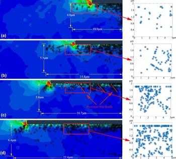
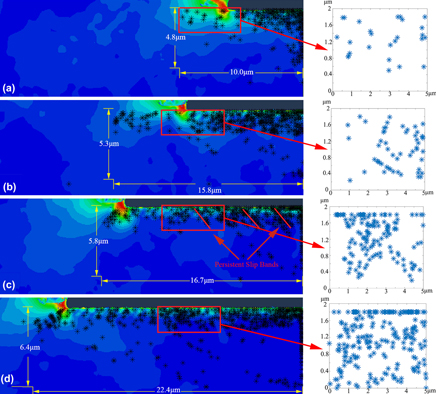
Subsurface states and their modifications induced by the complex interaction between the cutting force and residual force play a vital role in the micro-machining process. It leads to lots of fascinating microstructure consequences. To discover above the features, a series of snapshots of FEM-DDD observations were shown as Fig. 3, which demonstrated the generation and reaction process of subsurface damages. Meanwhile, a local representative zone was adopted to further reveal the detailed characteristics of subsurface microstructure changes. During simulations, a mass of dislocations nucleated from static random F–R sources would arrange themselves into specific configurations to the accommodation of the matrix deformation. These defects either formed dislocation dipoles on parallel slip planes, dislocation junctions and locks on crossed slip planes, or piled up against grain boundaries.
Dislocation distribution and the local dislocation crystal structure against the cutting distance (cutting speed 10 m/s and cutting depth 0.5 μm). (a) A cutting distance of 5 μm; (b) a cutting distance of 10 μm; (c) a cutting distance of 15 μm; (d) a cutting distance of 20 μm.

Acting under external stress, great quantities of dislocations were generated and extended in Fig. 3(a). Accompanying with the accumulation and release of cutting energy, the distribution of the subsurface damage layer continuously evolves with the increasing of the cutting length. Dislocations emitted in vertical direction downward promote the formation of dipoles immediately below the cutting tool. The interactions between the feed force and the thrust force give a boost to various evolution behaviors of subsurface defects, including dislocation processes of nucleation, motion, annihilation, and so on. The above results cause the interaction among dislocations and other possible defects and facilitate the build up of complicated dislocation networks, which are greatly favorable for generation and storage of internal stress in the workpiece subsurface.
As the cutting distance reached 5 μm, obvious dislocation lines which were nearly ±45° with the slip direction were formed in the representative zone, as shown in Fig. 3(b). Meanwhile, the shearing action of the cutting tool further promoted the quantity mushrooming of edge and screw dislocations. Simulation results indicate that the length of the subsurface damage layer indeed increases along the tool path, but its depth then basically remains stable. The underlying reasons are that the subsurface damage layer microstructure possesses a series of invariable formation mechanism during the steady cutting process. Specially, two types of subsurface defect structures can be identified, the near-surface damage layer (from upper surface to near 2 μm depth subsurface) and the deep-surface damage layer (from the bottom of near-surface damage layer to deeper substrate) respectively, which have totally different structural natures and defect distribution characteristics. It is noteworthy that the prediction of multilayer damage shows a satisfied agreement with the previous experimental phenomena, which suggested that the subsurface damage resulting from micro-cutting can permeate deeper into the base material than previous reported. Reference Thomas, Turnerb and Jackson10 Since the near-surface damage layer mainly occurs in a very narrow region of the subsurface, it easily forms subsurface work hardening because it is densely tangled among dislocations. Instead, the deep-surface zone may contain little free dislocations and localization obstacles under certain conditions and hence the slight dislocation slip without constraint would produce strain softening in the fundamental part. The above-obtained result coincides well with Guo et al., Reference Sun and Guo36 who argued that the hardness data measured in the deep subsurface are slightly less than those of the bulk material in some conditions. In addition, with the increase of the cutting length, lots of dislocations were hampered by vacancy cluster defects and locks, which lead to the formation of the subsurface hardening layer and restrain plastic deformation. Particularly, Fig. 3 showed that not only the near-surface damage layer but also the deep-surface zone formed unique dislocation bands at the moment of tool cut-in, which uninterruptedly migrated under the squeeze action of the cutting tool. Its reason is that the instantaneous impulsion of the cutting tool causes the continuous dislocation emission of grain boundary in the deeper subsurface zone.
With the proceeding of machining, dislocations were condensed into tangles. Subsurface matrix gradually generated several persistent slip bands (PSBs), as shown in Fig. 3(c). The PSBs as a crystal structure can form barriers to impede the sequent dislocation motion and then intensify the pile-up hardening effect in the subsurface. At the same time, serious external action further facilitated the elongation and reorientation of PSBs in shear direction. Since dense slip bands possess higher dislocation density than the rest of zone, the distribution of subsurface defects tends to be inhomogeneous, causing significant strain concentration. It is worth mentioning that the squash and stretch effect among PSBs and free-dislocation crystal structures may result in microcrack initiation, propagation, and coalescence. The above simulations are consistent with the previous experiment, where the principle mechanism for fracture crack initiation is the interaction between slip bands with subsurface grain boundaries or the specimen surface. Reference Ginting and Nouari9 After cutting, the influence of the external stress field on the deformation zone weakens sharply, but the severe asymmetry of internal stress distribution powerfully promotes succeeding defect structural evolution. At this stage, dynamic recovery is the main process in forming stable the subsurface structure, in which dislocations produced an entanglement structure at the near-surface zone in Fig. 3(d). It not only dominates the dislocation evolution on particular slip planes but also gives rise to subsurface grain refinement because the migration of dislocations induces an enormous vacancy migration energy in the subsurface damage layer and then the unbalance of the lattice energy transforms the original crystal into the independent subgrain until refined grain boundaries are constructed.
B. Influence of cutting depth on subsurface defect structure
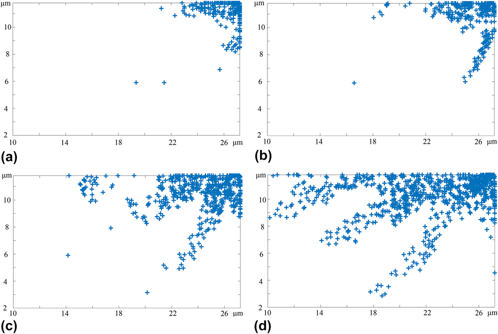
The cutting parameter plays an important role in the formation of the subsurface damage layer by influencing the propagation and retention of dislocations. To clearly illuminate its variation tendency, DD snapshots were specially extracted. According to various cutting depth classifications, cutting depths of 0.5, 1, 2, and 3 μm were used for studying subsurface structure changes, while the other machining parameters kept the same, i.e., the cutting speed was 10 m/s. Figures 4(a)–4(d) presented selected subsurface morphologies with various cutting depths when the cutting distance was 2.5 μm. As described in the previous section, two distinct subsurface deformation areas of the near-surface damage layer and deep-surface damage layer, each characterized by different distribution and array features, were found to constitute and keep subsurface deformation filed. From Fig. 4, we can get that varying cutting depths could lead to entirely different subsurface organizational structures. At small cutting depth in Fig. 4(a), dislocations primarily focused on the near-surface zone, and the slipping and climbing behavior of dislocations made a great contribution to the accommodation of microstructure deformation. Subsequently, upon undergoing further increase of the cutting depth, the near-surface damage layer consisted of a certain amount of piled-up dislocations and refined grain organizations in Fig. 4(b). Moreover, a larger cutting depth would activate dislocation nucleation and motion deeper down in the subsurface interior. This phenomenon can be explained as that increasing the cutting depth conducts a higher impact loading exerted on the workpiece, and a larger deviatoric stress is provoked in the interior material, hereby increasing the thickness of the subsurface damage layer in consequence. On the other hand, as the interaction of impact and friction between tool and workpiece, the subsurface damage layer gathers dislocations and forms dense shearing bands, as shown in Figs. 4(c) and 4(d). Specially, when the cutting depth is larger than 2 μm, it is found that the deep-surface dislocations tend to form a larger number of choroid dislocation bands, which slip forward along the glide system with an approximation angle of 30° and 60° to the cutting direction. With the increase of the axial depth of the cut, they gradually became wider and longer. Particularly, in comparison to subsurface damages in near-surface zone, the accumulation and propagation of dislocations in the deep-surface damage layer may result in a more serious distortion deformation and stress concentration, which has been studied in more detail later in this work.
Subsurface morphology under different depth of cut (a) 0.5 μm, (b) 1 μm, (c) 2 μm, and (d) 3 μm. (cutting speed = 10 m/s; cutting distance = 2.5 μm).
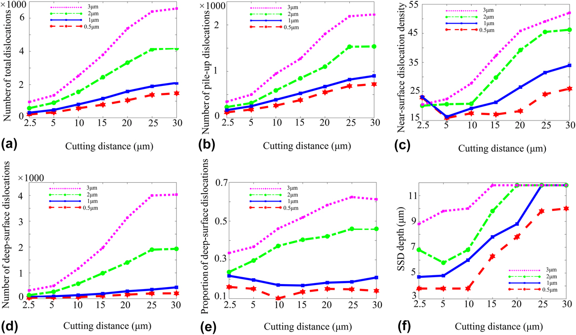
For the subsurface deformation zone, different sorts of evolution processes of damages with the increase of the cutting distance were shown in Fig. 5. In the initial stage of the microcutting process, cut-in impulse forces results that subsurface pre-existing dislocations usually fail to make timely structural adjustments. Therefore, many F–R sources of the titanium alloy have to take place local dislocation multiplication to relieve external stresses. It led to the increasing of dislocations in quantity, as shown in Fig. 5(a). Based on the above analysis, decreasing the cutting depth tends to produce a relative small hydrostatic pressure in the subsurface and indicates less demand for dislocation proliferation so that the number of subsurface dislocations changed slightly when the axial depth of the cut is less than 1 μm. Since dislocations are continuous annihilations and are removed from the simulation area in the micro-cutting process, the dislocation quantity kept stability essential when the cutting length is greater than 25 μm. Moreover, the rapid expansion of the dislocation density and quantity also boosted the odds of dislocation accumulation nearby cross slip dislocations, junctions, and grain and subgrain boundaries, which would govern the exhaustion hardening effect for the subsurface damage layer, as shown in Figs. 5(b) and 5(c). Additionally, the axial depth of the cut had a serious impact on the internal organizational structure of the deep-surface damage layer, thus the defect numbers and their proportion both sharply jumped when the cutting depth was above 2 μm in Figs. 5(d) and 5(e). Obstacles and impurities in the near-surface layer would impose restrictions on the locomotivity of the individual dislocation, which causes the starvation effect and aggravates the expansion of the subsurface damage layer. Therefore, as seen in Fig. 5(f), SSD depth curves are basically kept unchanged in the early stage, then presenting a rising trend until reaching the bottom of the simulation model.
Evolution of different types of subsurface damages under various cutting depths. (a) Number of subsurface dislocations; (b) number of pile-up dislocations; (c) change of the near-surface dislocation density; (d) number of deep-surface dislocations; (e) proportion of the deep-surface dislocation; (f) change of the subsurface damage layer depth.

C. Influence of cutting speed on subsurface defect structure
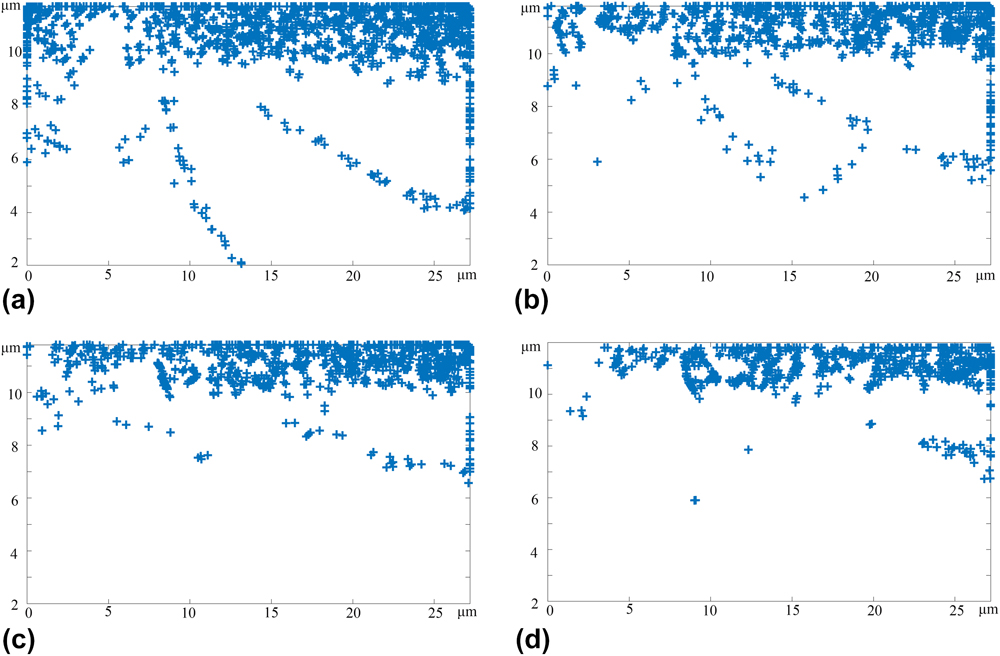
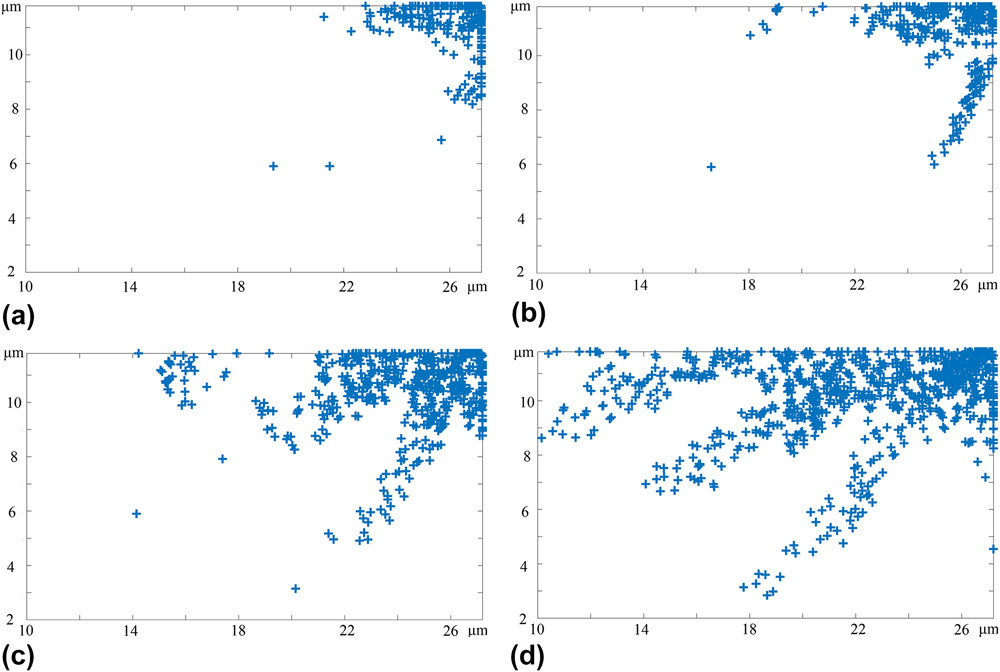
To reveal the influence of the cutting speed on the subsurface damage structure, several simulation models with various velocities set from 10 to 40 m/s, sharing a same depth of cut 1 μm, were developed. The microstructure of the machined subsurface shown in Fig. 6 was adopted to quantitatively illustrate the evolution mechanism of inner defects, in which the cutting length was 20 μm. The observations enable us to conclude that the machined subsurface presented various characteristics of the plastic feature and microstructure alteration from top to bottom. Comparing with different Figures, increasing cutting speed restrained the generation of the subsurface defect structure. Actually, the improvement of cutting speed directly raises the temperature in machined surface and subsurface region, which can significantly improve the diffusion constant of the partial dislocation of the titanium alloy and enhance the ability of the dislocation climb. Since the climbing process helps blocked dislocations jump out of intrinsic slip planes to bypass the local impurity particles and locks, the quantity of immobile defects came down dramatically in Figs. 6(a)–6(c). But once the cutting speed exceeded a specific level, the dislocations facilitated by the climb behavior would be more liable to be hindered by impenetrability dislocation bands and grain boundaries. Subsequently, the above piled-up phenomena result in the inhomogeneous distribution of subsurface damages and further promote continuous dynamic refinement within grain and subgrain in the near-surface damage layer. Furthermore, since the compatible plastic deformation always occurs in the refined grain, Reference Shin, Kim, Kim, Kim and Semiatin37 the workpiece subsurface tends to undergo further microstructure alteration without any contribution from dislocation evolution in the deep-surface zone, which can hinder the damages from propagating into the interior substrate and improve workpiece quality. As a result, when the cutting speed reached 40 m/s, discrete dislocations were hardly multiplied in the deep-surface damage layer and hence the thickness of the subsurface damage layer dropped rapidly in Fig. 6(d).
Subsurface morphology under different cutting speeds (a) 10 m/s, (b) 20 m/s, (c) 30 m/s, and (d) 40 m/s. (cutting depth = 1 μm; cutting distance = 20 μm).

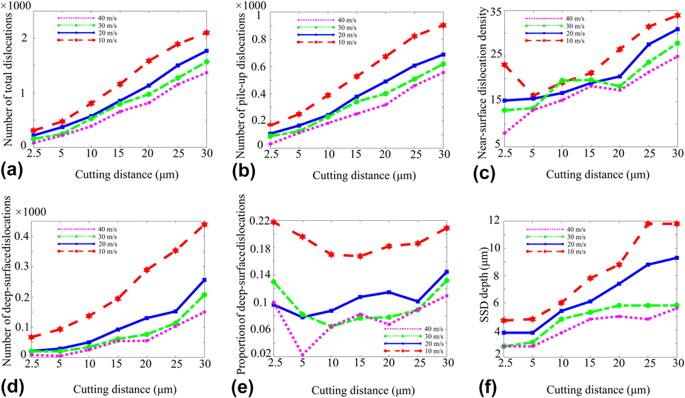
Figure 7 indicated different types of curves as a function of the cutting speed, where Figs. 7(a) and 7(b) presented the variation of total dislocations and pile-up dislocations, Fig. 7(c) showed the evolution law of dislocation density in the near-surface zone, Figs. 7(d) and 7(e) revealed the number of deep-surface defects and their proportion variations with the cutting distance, and Fig. 7(f) showed the changes of the SSD layer depth in the microcutting process. With a machined surface being formed, the subsurface substrate undergoes elastic deformation at first and then shearing via dislocation movement and grain evolution takes place. From Figs. 7(a) and 7(b), the samples with low cutting velocities usually contained a greater proportion of impeded dislocations due to a lower diffusion coefficient. Therefore, the bulk material has to maintain dislocation nucleation to inhibit the formation of a subsurface micro-crack caused by partial hardening in the near-surface damage layer. What is more, the amplitude of the dislocation number curve increased gradually when the removal velocity arrived at 10 m/s, which was much higher than that for other conditions. Moreover, since the back stress caused by obstacle particles always makes it difficult to reactivate F–R sources from where dislocations originated, the dislocation density in the near-surface zone would display a feature of temporary descending until the occurrence of secondary nucleation on neighboring glide planes, as shown in Fig. 7(c). As the cutting action goes on, the lasting consumption of pre-existing nucleation sources of the near-surface deformation zone promotes the initiation and propagation of line defects in the deep-surface damage layer when the cutting speed is sufficiently low. Meanwhile, fluctuating thermal stress also leads to a miniature dislocation emission effect from grain boundaries to the subsurface internal. Particularly, although grain refinement can decompose external pressure according to the previous research, the narrow lattice structure would suppress the generation of dislocation lines and bands if the refined grain size fits within the submicron scale. Reference Bai, Bai, Tong, Hu and He15 In summary, when the cutting speed was larger than 20 m/s, the curve slopes of deep-surface defects quantity and proportion both increased in the latter period in Figs. 7(d) and 7(e). As shown in Fig. 7(f), the increased cutting speed supported the reduction of the subsurface damage layer depth, which is opposed by the increase of the cutting depth. Since a high material removal rate (MRR) can be obtained by increasing the cutting depth and cutting speed, considering the influences of process parameters on SSD and MRR, a high cutting efficiency will be obtained while maintaining the subsurface quality.
Evolution of different types of damages in the subsurface under various cutting speeds. (a) Number of subsurface dislocations; (b) number of pile-up dislocations; (c) change of the near-surface dislocation density; (d) number of deep-surface dislocations; (e) proportion of the deep-surface dislocation; (f) change of the subsurface damage layer depth.

D. Influence of cutting parameters on subsurface inner stress distribution
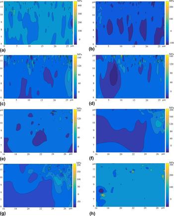
The above results indicate that the subsurface microstructure-forming process is mainly governed by the strong localization of dislocation evolution and dynamic balance of the tool-workpiece contact region. With the penetration of the outer tool, external kinetic energy is constantly transmitted into the matrix and is converted to internal energy via storing in subsurface defects. Once a particular threshold has been exceeded, dislocations would be rearranged into a lower energy structure. At last, most of the discrete dislocations form a stable self-balanced system within sufficient time durations, which directly results in the forming of a subsurface inner stress–strain field. In this section, to further carry out the distribution and gradient characteristics of the internal stress caused by damages, the influence of the cutting speed and depth on the above features in the feed direction was further calculated in Fig. 8.
Influence of cutting speed on subsurface inner stress distribution. (a) Cutting speed 10 m/s; (b) cutting speed 20 m/s; (c) cutting speed 30 m/s; (d) cutting speed 40 m/s. (depth of cut = 1 μm; cutting distance = 20 μm); Influence of the axial depth of cut on subsurface inner stress state distribution. (e) Cutting depth 0.5 μm; (f) cutting depth 1 μm; (g) cutting depth 2 μm; (h) cutting depth 3 μm. (cutting speed = 10 m/s; cutting distance = 5 μm).

Among all the cases, Figs. 8(a)–8(d) showed the influence of cutting speed on the subsurface inner stress state when the cutting distance reached 20 μm. At low cutting speeds, subsurface defects have to suffer from a more complicated and prolonged external stress state so that more of mobile dislocations were blocked by precipitates and obstacles in the near-surface zone, which directly resulted in the severe stress concentration features in Figs. 8(a) and 8(b). However, while the cutting speed increased in the feed direction, the amplitude of the subsurface inner stress σ11 decreased and reached a minimum of 160 MPa around 40 m/s, as shown in Figs. 8(c) and 8(d). It is noted that although the phenomenon of internal stress polarization was significantly alleviated accompanying an increase of the cutting speed, the quantity of stress concentration regions (SCRs) also increased. The result agrees well with previous simulations; in fact, it can be explained that the motions of dislocations from the local lattice to the neighboring lattices are more easily thwarted by the refinement grain so that a large amount of dislocations would be increasingly fragmented into different grains, which leads to the decrease of gradient magnitude of the inner stress.
Figures 8(e)–8(h) showed the evolution process of the subsurface inner stress under various cutting depths when the cutting length is 5 μm. Through comparison among figures, subsurface damages structure configurations evolved from simpleness to complexity, and the inner stress was increasingly polarized with the increase of the cutting depth. At the same time, rising energy aggregation facilitates dislocation nucleation and generates cross slip bands and straight slip bands which span multiple grains. In Fig. 8(e), sporadic SRCs were randomly distributed in the near-surface damage layer. As the axial depth of the cut increased, a distinct distinction can be found wherein the distribution area of high stress σ11 gradually enlarged, and the location of SRCs spilt over into the subsurface internal region step by step in Figs. 8(f)–8(h). The essential factor is that the large axial depth of the cut induces a serious shock wave into the titanium alloy subsurface, Reference Jiang, He, Gu, Wang and Cao38 which results in the distortion of grain boundaries and the aberrance of the lattice in the deep-surface layer [in Fig. 8(h)]. With the increase of accumulative inhomogeneity, the crowding in or out in lattice boundaries may further exacerbate the phenomenon of inner stress concentration in the surrounding lattices and result in an intergranular fracture at the internal deep-surface damage layer.
V. CONCLUSIONS
In this article, a trans-scale simulation framework was presented to reveal a detailed insight into the damage formation and propagation during microcutting of the titanium alloy process. The present study was particularly concerned about the dependency between cutting parameters and the subsurface defect structure. Following conclusions were obtained:
-
(1) The novel FEM modeling technique embedded with a discrete dislocation dynamics subroutine was able to reveal the interaction mechanism among dislocations and other defects. The predicted mechanism is identical with previous experimental findings on the machined subsurface, which demonstrates that the dislocation dynamics-based framework is a useful tool to quantitatively trace the microstructural evolution of the subsurface defect.
-
(2) The prime formation mechanisms of the subsurface defect structure are dislocation motion and grain refinement. During the steady micromachining process, the subsurface damage layer possesses a series of invariable characteristics such as, dislocation multiplication, slant dislocation lines, dense dislocation bands, and dynamic recrystallization.
-
(3) Two different natures of subsurface damage layers are indicated, the near-surface damage layer and the deep-surface damage layer, respectively. The emergence of the near-surface damage layer is always accompanied with the appearance of subsurface work hardening. The dislocation evolution in the deep-surface deformation zone can potentially produce the local strain softening phenomenon under certain processing conditions.
-
(4) The depth of the subsurface damage layer generated in the microcutting process is directly related to the cutting depth and cutting speed. Under the test cutting conditions, a large depth of cut results in a thick subsurface damaged layer and a high density of subsurface damage features. A high cutting speed would significantly boost the diffusion coefficient of dislocation, which can promote grain refinement and inhibit dislocation nucleation in the deep-surface damage layer.
-
(5) The internal stress will result in the distortion and aberrance of the subsurface lattice, and the distribution of internal stress patterns and SCRs is severely influenced by cutting parameters. The microcrack may be nucleated not only in the near-surface hardening zone but also in the internal deep-surface damage layer.
ACKNOWLEDGMENTS
This research work was jointly supported by the National Natural Science Foundation of China (Grant No. 51575138) and the State Key Program of National Natural Science Foundation of China (Grant No. 51535003).