1. INTRODUCTION
Vircators are incorporated by a special class of powerful microwave generators with an operating principle based on radiation from oscillating virtual cathode (VC). In the experiments, the record power of microwave radiation was emitted into an open space (Huttlin et al., Reference Huttlin, Bushell, Conrad, Davis, Ebersole, Judy, Lezcano, Litz, Pereira, Ruth, Weidenheimer and Agee1990). The reviews of vircators' constructions, their operating physics, and achievements are described in the book (Benford et al., Reference Benford, Swegle and Schamiloglu2007) and in the articles (Hoeberling & Fazio, Reference Hoeberling and Fazio1992; Rukhadze et al., Reference Rukhadze, Stolbetsov and Tarakanov1992; Dubinov & Selemir, Reference Dubinov and Selemir2002).
A typical vircator contains two cavities: in the first one, the high-current electric beam is produced and accelerated; and in the second cavity, this beam is decelerated by its own electric field and creates an oscillating VC. As a rule, the cavities are separated from each other by a screen grid or foil, which is transparent for electrons.
The papers (Miner et al., Reference Miner, Voss, Koslover, Miera, Cremer and Biggs1992; Dubinov et al., Reference Dubinov, Mikheev, Selemir and Sudovtsev1999) describe the results of vircators' investigation, where double anodes were used, which contain either two parallel flat foils or two parallel grids. As it is noticed, the presence of a second grid allowed changing the form of a potential well “cathode-VC” and ensure, for instance, stochastic resonance mode.
However, the scheme with double anodes examined in (Miner et al., Reference Miner, Voss, Koslover, Miera, Cremer and Biggs1992; Dubinov et al., Reference Dubinov, Mikheev, Selemir and Sudovtsev1999), where the distance between anode foils did not differ greatly from the width of diode gap and the distance from anode to VC, and the processes with big distances between foils were omitted. This variant is covered by the present study, wherein 2.5D particle-in-cell (PIC) simulation of magnetoinsulated two-foil vircator by the KARAT code (Tarakanov, Reference Tarakanov1992) was performed.
2. GEOMETRY OF TWO-FOIL VIRCATOR AND THE ELECTRONS’ DYNAMIC THEREIN
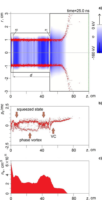
The simplest construction of two-foil magnet-isolated vircator, containing two coaxial cylindrical cavities of a same length L = 50 cm, was chosen. The diameter of the first cavity is ∅1 = 3 cm, and of the second is ∅2 = 6 cm. The cavities are adjacent to each other with boundaries and are separated from each other with foil #1. The vacant left boundary of the first cavity was closed by a conducting wall, through which a tubular electric beam was injected, whereas the vacant right boundary of the second cavity was open. There was one more foil #2 inside the first cavity, position of which defined the value of gap d between foils. The vircator's geometry is shown in Figure 1a.
The results of a two-foil vircator's simulation: (a) the vircator's geometry (the scale regarding r and z are not identical), the instant configuration portrait of electronic beam, and map of the Coulomb potential field (color gradation); (b) the beam's instant phase portrait; (c) electrons' density along the line r = 1 cm.

The construction is emerged into an axially symmetric magnetic field, which is homogeneous in the first cavity and with value decreasing in the second cavity. Magnetic field in the homogeneous part had a value of 10 kG.
It was set that the tubular electric beam with a continuous current was injected inside the first cavity from its left vacant boundary. The external beam's diameter ∅beam = 1 cm, and the current's wall thickness δ = 1 mm.
After passing the first cavity, the beam comes into the second cavity, where VC is formed. In the second cavity also, the electric beam landed on the side wall under action of a heterogeneous magnetic field. The configuration instant beam's portrait in vircator is shown in Figure 1a.
Upon simulation, the analysis of electron beam phase portrait's evolution was carried out; at the same time, a special attention was paid to the beam's behavior at the big values of d.
Let us demonstrate the simulation results for the following parameters: the distance between anode foils is d = 47 cm, the beam current is I = 2.5 kA, and the energy of injected electrons is ε = 150 keV. It was assumed that the front of current pulse is very short. The set parameters are close to the vircators' parameters described in (Alyokhin et al., Reference Alyokhin, Dubinov, Selemir, Shamro, Shibalko, Stepanov and Vatrunin1994; Shukla & Shyam, Reference Shukla and Shyam2013).
It was found that initially two VCs are generated in the second cavity near both the foils by the moment of time t = 5 ns, which turn the part of electrons back, against the injection's direction. Further the regions, occupied with these VCs, where the electrons' energy is decreased, and the density is, vice versa, increased, start lengthening toward each other. The similar lengthy VCs in magnetoinsulated vircators were observed earlier in (Ignatov & Tarakanov, Reference Ignatov and Tarakanov1994) and were therein named “the beam's squeezed state.” The dynamics of regions with a beam's squeezed state was researched intensively in (Dubinov, Reference Dubinov1997; Dubinov et al., Reference Dubinov, Efimova, Kornilova, Saikov, Selemir and Tarakanov2004; Donets et al., Reference Donets, Donets, Syresin, Dubinov, Makarov, Sadovoy, Saikov and Tarakanov2009).
Figure 1b demonstrates the electron beam's phase portrait in two-foil vircator by the moment t = 25 ns, when two places with a squeezed state of beam came significantly close to each other, and the phase bubbles emerged with electrons performing a circular phase motion on its contour. Hence, such phase bubbles are often called electronic phase vortexes (Shukla et al., Reference Shukla, Mamun and Eliasson2004; Eliasson & Shukla, Reference Eliasson and Shukla2006).
The electrons' energy within the regions of a squeezed state is significantly lower than the injection's energy, and the density of electrons is increased. This fact is confirmed by the dependence of electrons' density n e(z) along the line r = 1 cm (Fig. 1c) and by the map of Coulomb potential field (color gradation on Fig. 1a).
By the time t = 50 ns, the phase vortex collapses and both the regions with a beam's squeezed state are united.
Qualitatively, such a phase portrait's evolution occurred at different d values ≈50 cm. For a small d value, the circulating phase vortex and the beam's squeezed state inside the first cavity appear between its left boundary and the foil #2.
In the extreme case d = 0 cm, which corresponds to the absence of foil #2, the squeezed state extends against the beam injection's direction, and the phase vortex did not appear.
The analysis of simulation results allowed making the following assumption. If such two-foil magnetoinsulated vircators are used for the purposes of microwave generation, it should be expected that the phase vortexes and VCs in the first cavity can induce modulating effect on the electronic beam the same as the modulating drift gap in unmagnetized vircators with electron premodulation (Kitsanov et al., Reference Kitsanov, Klimov, Korovin, Kurkan, Pegel and Polevin2002; Korovin et al., Reference Korovin, Kurkan, Loginov, Pegel, Polevin, Volkov and Zherlitsyn2003). It should ensure the increase of microwave generation.
3. THE GENERATING CHARACTERISTICS OF TWO-FOIL VIRCATOR
In order to define the two-foil vircator's generating characteristics, the following calculations were carried out:
-
• of the Poynting flux through an open boundary of the second cavity. This flux is equated to a microwave radiation's power;
-
• of Fourier spectra of current longitudinal component's oscillation in the second cavity, allowing to find the values of microwave-generated frequencies.
3.1. Power Characteristics
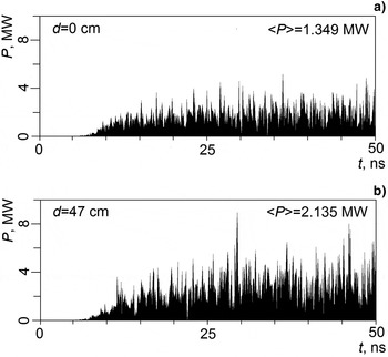
Two histories of the Poynting flux are shown in Figure 2: for one-foil vircator (Fig. 2a) and for two-foil vircator at d = 47 cm, operating in the electronic phase vortex mode (Fig. 2b). The average values of microwave power for a period of t = 0–50 ns are also shown as 〈P〉. It is obvious that the average power of two-foil vircator at d = 47 exceeds the average power of one-foil vircator by ~1.6 times.
The time dependences of Poynting flux (the average microwave power 〈P〉 for a period of t = 0–50 ns is mentioned in the top right corner): (a) for one-foil vircator at d = 0 cm; (b) for two-foil vircator at d = 47 cm.

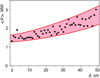
Similar calculations for d from the range of 0–50 cm with step 1 cm were carried out. The outputs of these calculations are depicted in Figure 3. Apparently, the average power for all d≠0 values is higher than for one-foil vircator. The calculated dependence is of an irregular type (dots in the scheme of Fig. 3), but, certainly, it implies the trend of increase (the painted area in Fig. 3). Moreover, for the value of d = 49 cm, the relation of two-foil vircator's average power to the average power of one-foil vircator was equal to ~2 times.
The dependence of the two-foil vircator's average microwave generation power on d value: the points are calculations results; the last left point is for one-foil vircator at d = 0 cm; the painted area is approximation.

The observed increase of an average power is explained by the existence of electronic phase vortex. This phase vortex represents the potential hole in the configuration space, and the oscillating electrons therein ensure the increase of generation power.
3.2. Spectral Characteristics
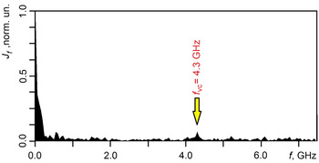
For the vircator's spectral characteristics' identification, the history of current's density J z(t) in the second cavity near VC was taken into account, then the Fourier transform J f(f) was calculated. The outcome of such a calculation for the chosen vircator's parameters is represented in Figure 4. It was defined that the vircator's primary generation frequency is f VC = 4.3 GHz.
The normalized Fourier transform of the current density's dependence on time near VC.

It was found that a simple current's injection variation within the interval 2–10 kA does not lead to the change of frequency f VC. It may be explained by the fact that whatever current's value we inject, not all the electrons reach the second cavity, but only such their quantity, which is defined by the limiting current of the first cavity (Dubinov & Efimova, Reference Dubinov and Efimova2003).
The change of the injected electron's energy is necessary for managing the vircator's frequency. Hence, in the event of energy increase, the limiting current for the first cavity increases and a bigger number of electrons take part in VC's formation in the second cavity. It leads to the increase of frequency f VC. For example, if the energy value of injected electrons is equal to ε = 250 keV and the injected beam's value is I = 2.5 kA, then the frequency f VC = 5.0 GHz.
4. CONCLUSIONS
PIC simulation of two-foil magnetoinsulated vircator and the beam's phase portrait evolution demonstrated the formation of two regions with a squeezed condition of an electronic beam, separated from each other by electron phase vortex.
The power of two-foil vircator's microwave generation was calculated. It was proven that in the phase vortex mode, the power of vircator's microwave frequency can excel the outcome power of a usual single-foil vircator by two times at the same beam's parameters.
The spectral characteristics of two-foil vircators were studied. It was found that it is necessary to change the energy of electrons for the variation of primary microwave generation frequency.