1. Introduction
Many safety systems for example aircrafts, ships, and unmanned aerial vehicles (UAV) are designed by redundant effectors and actuators in order to satisfy objectives such as reliability, controllability, flexibility, and fault tolerance [Reference Edwards, Lombaerts and Smaili1–Reference Naderi, Johansen and Sedigh4]. In such over-actuated systems, the number of actuators is greater than the number of controlled variables [Reference Frank5–Reference Abdi, Nahavandi, Frayman and Maciejewski7]. Over-actuated systems can remain stable and keep the control performance in the case of fault occurrence, actuators’ limitations, or severe disturbances.
In this paper, the modular structure used in the fault-tolerant control scheme employs the control allocation strategies. In this structure, the control system is divided into the two parts: (1) The main controller which produces the desired virtual control in order to achieve the control goals such as maintaining closed-loop stability and set-point tracking and (2) the control allocator that distributes the desired virtual control among the actuators such that their constraints are satisfied [Reference Tohidi, Khaki Sedigh and Buzorgnia8].
A wide range of the control allocation methods are available in the literature [Reference Johansen and Fossen9, Reference Bordignon10]. The pseudo-inverse approach is the simplest method that does not consider the actuator constraints in its basic design. In order to handle the actuator constraints, some modifications such as the redistributed pseudo-inverse in ref. [Reference Oppenheimer, Doman and Bolender11], direct allocation in refs. [Reference Bordignon10, Reference Durham12], daisy chain in ref. [Reference Buffington and Enns13], and the pseudo-inverse correction along the null space [Reference Tohidi, Khaki Sedigh and Buzorgnia8] are presented. In addition, the linear programming (LP) in ref. [Reference Johansen and Fossen9], the quadratic programming (QP) in ref. [Reference Petersen and Bodson14], reinforcement learning in ref. [Reference Kolaric, Lopez and Lewis15], and an adaptive approach in ref. [Reference Tohidi, Yildiz and Kolmanovsky16] are employed to solve the control allocation problem.
Nowadays, the unmanned aerial vehicles (UAV), in particular the Vertical Take-Off and Landing (VTOL) vehicles, are attracting much attention. They can be employed in various applications, such as sport events, traffic surveillance, and transportation [Reference Noormohammadi-Asl, Esrafilian, Arzati and Taghirad17–Reference Meng, He and Han20]. Stability of the UAVs in the face of fault and actuators’ saturations is crucial. Octorotor has four redundant actuators as compared to the quadrotor. Therefore, under critical situations such as faulty motors, actuators’ saturations, or severe disturbances, the control allocation unit can be used to manage redundant actuators in order to achieve an acceptable closed-loop operation [Reference Sadeghzadeh21].
In ref. [Reference Sadeghzadeh, Chamseddine, Zhang and Theilliol22], a LQR controller is implemented for a quadrotor in order to achieve a fault-tolerant control system which shows that using control allocation improves system performance in the face of actuator faults. In ref. [Reference Alwi and Edwards23], the sliding mode controller and the pseudo-inverse strategy are used as the main controller and the control allocator for an octorotor, respectively. The system tolerance against the actuators and sensors fault is investigated, whereas the actuators’ saturations are not considered. Although active controllers such as the sliding mode controller are effective to encounter system faults, they have a limited performance under severe conditions [Reference Dydek, Annaswamy and Lavretsky24]. In such cases, the control allocation unit can provide more effective solutions. Although the sliding mode controller and integral sliding mode controller are highly robust against disturbances and uncertainties, they are still inefficient in the face of severe faults [Reference Li, Zhang and Gordon25–Reference Li27]. In ref. [Reference Marks, Whidborne and Yamamoto28], PD controllers and the redistributed pseudo-inverse method are employed as the main controller and the control allocation unit, respectively. However, fault identification, actuators’ saturations, and practical issues are not considered. In ref. [Reference Ijaz, Fuyang and Hamayun29], a fault estimation and fault-tolerant control based on the control allocation strategy is used, but physical limitations and implementation are not taken into account.
The main goal of this paper is to investigate the performance of an over-actuated octorotor in the face of actuators fault and saturation while it hovers. To make the system robust, we proposed a control scheme including a fault detection and diagnosis unit based on the sliding mode observer and a fault-tolerant unit based on control allocation. In particular, the paper focuses on actuator saturation, its effects on closed-loop stability and performance, and using constrained control allocation strategy to deal with this issue. In addition, the performance of each unit and the actuator saturation effects are evaluated through experimental studies.
This paper is organized as follows. Octorotor dynamic model is presented in Section 2. Design of the main controller and the fault detection method are presented in Sections 3 and 4, respectively. In Section 5, control allocation unit and actuators’ saturations are investigated. In Section 6, the experimental system is introduced and the results are illustrated. The concluding remarks are given in Section 7.
2. Octorotor dynamic model
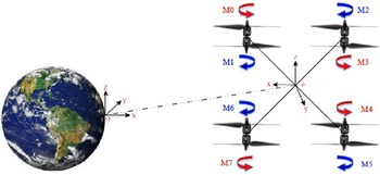
In the designed coaxial octorotor, the rotors are distributed as presented in Fig.1. Each arm ends with two coaxial counter-rotating motors. The octorotor dynamic model is similar to the quadrotor UAV model and is briefly described. More details can be found in ref. [Reference Marks, Whidborne and Yamamoto28].
 \begin{equation} \left\{ \begin{array}{l} \ddot x = \left( {\cos\phi \sin\theta \cos\psi + \sin\phi \sin\psi } \right)*\dfrac{{{u_f}}}{m}\\[8pt] \ddot y = \left( {\cos\phi \sin\theta \sin\psi - \sin\phi \cos\psi } \right)*\dfrac{{{u_f}}}{m}\\[4pt] \ddot z = \left( {\cos\phi \cos\theta } \right)*\frac{{{u_f}}}{m} - g\\[4pt] \dot p = \frac{{{I_y} - {I_z}}}{{{I_x}}}qr - \frac{{{J_r}}}{{{I_x}}}q{\rm{\Omega }} + \frac{1}{{{I_x}}}{T_\phi }\\[4pt] \dot q = \frac{{{I_z} - {I_x}}}{{{I_y}}}pr + \frac{{{J_r}}}{{{I_y}}}p{\rm{\Omega }} + \frac{1}{{{I_y}}}{T_\theta }\\[4pt] \dot r = \frac{{{I_x} - {I_y}}}{{{I_z}}}pq + \frac{1}{{{I_z}}}{T_\psi } \end{array} \right.\end{equation}
where
 $\ x$
,
 $\ y$
, and
 $\ z$
, are the coordinates of the UAV’s center of mass in the fixed Earth frame OXYZ, and
 $\phi $
,
 $\theta, $
and
 $\psi$
are the Euler angles. p, q, and r are the roll, pitch and yaw rates, and
 $\dot p$
,
 $\dot q,$
and
 $\dot r$
are their accelerations with respect to the body frame oxyz. m is the vehicle’s mass.
 $\ I_{x/y/z}$
are moments of inertia of the UAV along the x, y, z axis, and
 $J_r$
is the rotor inertia.
 $\Omega$
is the rotors’ relative speed [Reference ElKholy30] which is defined as
 $\Omega = \omega_1 + \omega_2 + \omega_5 + \omega_6 - \omega_0 - \omega_3 - \omega_4 - \omega_7$
.
The coaxial octorotor and the reference frames.

Since the roll, pitch, and yaw rates
 $[p\ q\ r]$
and their derivatives are measured with respect to the body frame system, and the Euler angles
 $[\phi $
 $\theta $
 $\psi]$
and their derivatives are measured based on the fixed Earth frame system, so a transformation matrix is needed as follows:
 \begin{equation}\begin{array}{l} \left[ \begin{matrix}{\dot{\phi }} \\{\dot{\theta }} \\{\dot{\psi }} \\\end{matrix} \right]=\left[ \begin{matrix}1 & \sin \phi \tan \theta & \cos \phi \tan \theta \\0 & \cos \phi & -\sin \phi \\0 & \sin \phi /\cos \theta & \cos \phi /\cos \theta \\\end{matrix} \right]\left[ \begin{matrix}p \\q \\r \\\end{matrix} \right]\end{array}\end{equation}
In case of small angle deviation, the transformation can be approximated as
 $\dot{\phi} =p$
,
 $\dot{\theta}=q $
, and
 $\dot{\psi}=r$
[Reference ElKholy30].
In the presented model (1), the total thrust
 $\ u_f$
, and the three input torques
 $\ T_{\phi}$
,
 $\ T_{\theta,}$
and
 $\ T_{\psi}$
on the roll, pitch and yaw directions are the control inputs and are given by:
 \begin{equation}\left\{ \begin{array}{l}{u_f} = {F_{01}} + {F_{23}} + {F_{45}} + {F_{67}}\\{T_\phi } = \left( {{F_{67}} + {F_{45}} - {F_{23}} - {F_{01}}} \right)*l*\dfrac{{\sqrt 2 }}{2}\\[5pt]{T_\theta } = \left( {{F_{23}} + {F_{45}} - {F_{67}} - {F_{01}}} \right)*l*\dfrac{{\sqrt 2 }}{2}\\{T_\psi } = \left( {{\tau _0} + {\tau _3} + {\tau _4} + {\tau _7}} \right) - \left( {{\tau _1} + {\tau _2} + {\tau _5} + {\tau _6}} \right)\end{array} \right.\end{equation}
where l is the arm’s length, and
 \begin{equation}\begin{aligned}{F_{ij}} &= {\alpha _{ij}}\left( {{F_i} + {F_j}} \right)\left( {1 + \frac{{{S_s}}}{{{S_{prop}}}}} \right)\end{aligned}\end{equation}
where
 $F_i$
is the force that each motor produces and
 ${\alpha _{ij}}$
is the coefficient of loss of aerodynamic efficiency due to the aerodynamic interference between the upper and lower propellers.
 ${S_s}$
denotes the propeller’s surface,
 ${S_{prop}}$
is the surface of the circle that the propeller would produce during its rotation [Reference Saied, Lussier, Fantoni, Francis, Shraim and Sanahuja31].
It is necessary to find the relation between force (
 ${F_{\!i}}$
) and torque(
 ${\tau_i}$
) with PWM because in the designed system, force, and torque of each motor is controlled by PWM signals. By assuming that motors conditions are the same, derivations of one of the motors are provided as follows [Reference ElKholy30].
2.1. Motor force
Initially, the force generated by a motor is computed as:
 \begin{equation}\left\{ {\begin{array}{*{20}{c}} {\tau = {K_t}\left( {I - {I_0}} \right)}\\ {V = I{R_m} + {K_v}\omega } \end{array}} \right.\end{equation}
where
 ${I_0}$
, V,
 ${K_v}$
,
 $\tau$
,
 ${K_t}$
, I,
 ${R_m}$
, and
 $\omega$
are the motor no-load current, the motor voltage, the back-EMF per RPM, the motor torque, aerodynamic translation coefficient, motor current, motor circuit resistance, and angular body rate, respectively. Then, the power can be calculated as:
 \begin{equation}P = IV = \frac{{\left( {\tau + {K_t}{I_0})({K_t}{I_0}{R_m} + \tau {R_m} + {K_t}{K_v}\omega } \right)}}{{K_t^2}}\end{equation}
In this model, the motor’s resistance is ignored, the linear relation between the power and the angular velocity is obtained as follow:
 \begin{equation}P \approx \frac{{\left( {\tau + {K_t}{I_0})({K_v}\omega } \right)}}{{{K_t}}}\end{equation}
It is assumed that
 ${K_t}{I_0} \ll \tau$
as
 ${I_0}$
is the no-load current which is negligible. Finally, for the motor output power and angular velocity of the motor, we have:
 \begin{equation}P \approx \frac{{{K_v}}}{{{K_t}}}\tau \omega\end{equation}
The amount of energy that the motor expends in a given time period is equal to the force generated on the propeller times the displacement of the air which the propeller moves (
 $P.dt = F.dx$
). Equivalently, the power is equal to the thrust T, times the air velocity
 $v_h$
:
 \begin{equation}P = F\frac{{dx}}{{dt}} = T{v_h}\end{equation}
According to the momentum theory, the relation between the air velocity when hovering and thrust is as follows:
 \begin{equation}{v_h} = \sqrt {\frac{T}{{2\rho A}}}\end{equation}
where
 $\rho $
and A are the surrounding air density and the area swept out by the rotor, respectively. On the other hand, we know that
 $\tau = r \times F$
. Therefore, in this motor, the relation between the thrust and the torque is considered using a constant coefficient
 ${K_\tau }$
, which depends on the blade specification and characteristics. Combining (8)–(10) yields:
 \begin{equation}\left\{ \begin{array}{l}P = \frac{{{K_v}}}{{{K_t}}}\tau \omega = \dfrac{{{K_v}{K_\tau }}}{{{K_t}}}F\omega \\[8pt] P = F{v_h} = \dfrac{{\sqrt {{F^3}} }}{{\sqrt {2\rho A} }}\end{array} \right.\,\,\,\,\,\,\,\,\,\,\,\,\, \Rightarrow \,\,\,\,\,\,\,\,\,\,\,F = {\left( {\frac{{{K_v}{K_\tau }\sqrt {2\rho A} }}{{{K_t}}}\omega } \right)^2} = {k_f}{\omega ^2}\end{equation}
where
 $k_f $
is the thrust coefficient. The motors thrust drives the Z axis and generates the torques in the pitch and roll directions. The torque generated by the motors causes rotational motion of the yaw angle, which is further calculated as follow.
2.2. Motor torque
The frictional force is obtained by using the drag equation from the fluid dynamics:
 \begin{equation}{F_D} = \frac{1}{2}\rho {C_D}A{v^2}\end{equation}
where
 $\rho $
is the density of the surrounding fluid, A is the reference area, and
 ${C_D}$
is a dimensionless constant. By using the drag force equation, the torques generated by the motors are as follows:
 \begin{equation}{\tau _i} = \frac{1}{2}\rho {C_D}A{v^2} = \frac{1}{2}\rho {C_D}A{\left( {\omega r} \right)^2} = {K_t}\omega _i^2\,\,\,\,\,\,\,\,\,\,\,\,i = 0,...7\end{equation}
where r is the propeller radius and
 ${K_t}$
is called the reaction torque coefficient.
The forces are expressed as follows based on the motors speed:
 \begin{equation}\left\{ {\begin{array}{*{20}{c}} {{F_i} = {K_f}\omega _i^2}\\[5pt] {{\tau _i} = {K_t}\omega _i^2} \end{array}\;\;\;\;\;\;\;\;\;\;\;i = 0,\; \ldots ,\;7} \right.\end{equation}
Brushless DC motors typically have their own embedded controllers, and they work with a Pulse Width Modulation (PWM) signal. The voltage supplied (PWM) to the brushless DC motors is directly proportional to the angular velocity (
 ${\omega}$
) [Reference ElKholy30].
3. Controller design
A control strategy for stabilizing the octorotor while hovering is presented in this section. When the octorotor is stabilized on hovering, the roll and pitch angles are kept near zero. So, considering the octorotor’s dynamic model, the system is linearized around the equilibrium hover point with the following assumptions:
 \begin{equation}\left\{ {\begin{array}{*{20}{l}} {\dot z = \dot \theta = \dot \phi = \dot \psi = 0}\\ \begin{array}{l} \theta \approx \phi \approx 0\;\;,\;\;\;\;\;z = {z_0}\;\;,\;\;\;\;\psi = {\psi _0} \\ \sin (\theta ) \approx \theta \,\,\,\,\,\,\,\,,\,\,\,\,\,\,\cos (\theta ) \approx 1 \end{array} \end{array}} \right.\end{equation}
The height equation around the hover point is simplified as follows:
 \begin{equation}\ddot z = \frac{{{u_f}}}{m} - g\end{equation}
where
 ${\ddot z}$
is the height acceleration, and also for (1):
 \begin{equation}qr \approx pr \approx pq \approx \dot \theta \dot \psi \approx \dot \phi \dot \psi \approx \dot \phi \dot \theta \approx 0\,\,\,\,\,\; \to \,\,\,\,\,\,\left\{ {\begin{array}{*{20}{c}} {\dot p = \frac{1}{{{I_x}}}{T_\phi }}\\[5pt] {\dot q = \frac{1}{{{I_y}}}{T_\theta }}\\[5pt] {\dot r = \frac{1}{{{I_z}}}{T_\psi }} \end{array}} \right.\end{equation}
Considering
 $\;{u_f} = mg$
, the linearized system transfer functions around the hover point are as follows:
 \begin{equation}\left[ {\begin{array}{*{20}{c}} \phi \\[12pt] \theta \\[12pt] \psi \end{array}} \right] = \left[ {\begin{array}{*{20}{c@{\quad}c@{\quad}c}} {\dfrac{{{k_\phi }}}{{{s^2}}}}&0&0\\ 0&{\dfrac{{{k_\theta }}}{{{s^2}}}}&0\\ 0&0&{\dfrac{{{k_\psi }}}{{{s^2}}}} \end{array}} \right]\left[ {\begin{array}{*{20}{c}} {{T_\phi }}\\[12pt] {{T_\theta }}\\[12pt] {{T_\psi }} \end{array}} \right]\end{equation}
where s is the Laplace operator and
 $k_{\phi/\theta/\psi}=1/I_{x/y/z}$
.
The octorotor is studied in the hover mode, and slight angle deviations are used to provide the required responses. This linearization of the system model is exploited to show that the octorotor has a linear behavior near the hover point. Hence, using PID controllers which are considered as linear controllers is reasonable. Simulation results are provided in Fig. 2 to illustrate that the linear model can sufficiently approximate the nonlinear model in open-loop mode. Note that
 $u_f$
is generated in a way that
 $u_f/m - g > 0$
, and also
 $T_{\phi/\theta/\psi}$
are considered as sine waves with a small magnitude to keep the system’s angles near the hover point.
Open-loop responses of linear and nonlinear models.

For the actual system, since there is no interaction in the hover condition, four separate controllers can be designed for the angles and height. PD controllers are used for the angles control, and a PID controller is employed for the height control. In order to get convenient maneuverability, the angles control need to be fast enough, so a PD controller is a better choice compared to a PID controller. On the other hand, based on the Eq. (16) using a PD controller for the system’s height results in a zero pole in the closed-loop transfer function, so according to the final value theorem it causes steady-state error. Therefore, a PID controller is used to solve the set-point tracking problem. The following PD/PID controllers are implemented:
 \begin{equation}\left\{ \begin{array}{l}{U_\phi}(k) = {K_{P\phi}}{e_\phi}(k) + {K_{D\phi}}[{e_\phi}({k}) - {e_\phi}(k-1)]/dT\\[5pt] {U_\theta}(k) = {K_{P\theta}}{e_\theta}(k) + {K_{D\theta}}[{e_\theta}({k}) - {e_\theta}(k-1)]/dT\\[5pt] {U_\psi}(k) = {K_{P\psi}}{e_\psi}(k) + {K_{D\psi}}[{e_\psi}({k}) - {e_\psi}(k-1)]/dT\\[5pt] {U_z}(k) = {K_{Pz}}{e_z}(k) + {K_{Dz}}[{e_z}({k}) - {e_z}(k-1)]/dT + \\[5pt] \,\,\,\,\,\,\,\,\,\,\,\,\,\,\,\,\,\,\,\,\,\,\,\,\,\,\,\,\,\,\,\,\,\,\,\,\,\,\,\,\,\,\,\,\,\,\,\,\,\,\, + {K_{Iz}}\left[\sum_{i=1}^{k}{e_z}(k)\right]*dT\end{array} \right.\end{equation}
where
 $U_{\phi}, U_{\theta}, U_{\psi}$
, and
 $U_{z}$
are the controllers outputs which correspond to
 $T_{\phi}, T_{\theta}, T_{\psi}$
, and
 $u_{f}$
in Eq. (3) respectively. To tune the octorotor controllers, the Ziegler-Nichols method is employed [Reference Åström and Hägglund32, Reference He and Zhao33]. In order to use Ziegler-Nichols, two parameters including maximum value of the proportional gain
 $K_p$
in which the system starts to oscillate and the frequency of the oscillation are needed to be determined. Thus, to obtain these parameters, in the first step, a small value is assigned to
 $K_p$
, and then, it is gradually increased until the octocoptor begins to oscillate. Consider the maximum value of the
 $K_p$
as
 $K_m$
and the oscillation frequency as
 $f_0$
. Then, based on the Ziegler-Nichols table the PID and PD controllers coefficients can be determined. Finally, experimentally adjusting the performance criteria such as settling time and overshoot results in a proper controller tuning. The coefficients’ values of each controller are provided in Table I:
PID controllers parameters for the actual octorotor.

4. Fault detection and diagnosis
Sensor, structural, component, and actuator faults may occur in the octorotor [Reference Saied, Lussier, Fantoni, Shraim and Francis34–Reference Zhang, Chamseddine, Rabbath, Gordon, Su, Rakheja, Fulford, Apkarian and Gosselin36]. This paper is mainly focused on the actuator faults.
The fault detection unit adaptively detects and isolates actuator faults in the system by calculating residuals. A nonlinear sliding mode observer is employed to estimate the Euler angles and their velocities. By calculating the system angular velocities and comparing with the measured angles that are provided by the Inertial Measurement Unit (IMU), the residuals are generated. In this section, the residual generation method and then the residual analysis that allows to detect and isolate faults in the system are presented.
The angular velocities are estimated using the following nonlinear sliding mode observer [Reference Saied, Lussier, Fantoni, Francis, Shraim and Sanahuja31]:
 \begin{equation}\left\{ \begin{array}{l}{\dot {\hat x}_1}(t) = {{\hat x}_2} + {\mu _1}\\[5pt] {\dot {\hat x}_2}(t) = \dfrac{{{I_y} - {I_z}}}{{{I_x}}}{{\hat x}_4}{{\hat x}_6} - \dfrac{{{J_r}}}{{{I_x}}}{{\hat x}_4}\Omega + \dfrac{1}{{{I_x}}}{T_\phi } + {\mu _2}\\[4pt]{\dot {\hat x}_3}(t) = {{\hat x}_4} + {\mu _3}\\[4pt]{\dot {\hat x}_4}(t) = \dfrac{{{I_z} - {I_x}}}{{{I_y}}}{{\hat x}_2}{{\hat x}_6} + \dfrac{{{J_r}}}{{{I_y}}}{{\hat x}_2}\Omega + \dfrac{1}{{{I_y}}}{T_\theta } + {\mu _4}\\[4pt]{\dot {\hat x}_5}(t) = {{\hat x}_6} + {\mu _5}\\[4pt]{\dot {\hat x}_6}\left( t \right) = \dfrac{{{I_x} - {I_y}}}{{{I_z}}}{{\hat x}_2}{{\hat x}_4} + \dfrac{1}{{{I_z}}}{T_\psi } + {\mu _6}\end{array} \right.\end{equation}
The sliding mode variables and gains are defined as follows:
 \begin{equation}\begin{array}{l}\left\{ \begin{array}{l}{\mathbf X} = {\left[ {\phi \;\;\dot \phi \;\;\theta \;\;\dot \theta \;\;\psi \;\;\dot \psi } \right]^T}\\[5pt] \hat{\mathbf{X}} = {\left[ {{\hat \phi} \;\;\dot {\hat \phi} \;\;{\hat \theta} \;\;\dot {\hat \theta} \;\;{\hat \psi} \;\;\dot {\hat \psi} } \right]^T}\end{array} \right.\\ \\\left\{ {\begin{array}{*{20}{c}} {{\mu _i}\;\;\;\; = {K_i}sign\left( {{x_i} - {{\hat x}_i}} \right)\;\;\;\;}\\[5pt] {{\mu _{i + 1}} = {K_{i + 1}}sign\left( {{x_i} - {{\hat x}_i}} \right)} \end{array}\;\;\,\,\,\,\,\,\,\;\;\;\;i = 1,3,5} \right.\end{array}\end{equation}
where X and
 $\hat X$
are the measured state variables and their estimations, and
 ${K_i}(i=1, ...,\,6)$
are positive gains. The observer error dynamics are given by
 $\dot{\tilde{x}}_i = x_i - \hat{x}_i $
. According to ref. [Reference Saied, Lussier, Fantoni, Francis, Shraim and Sanahuja31], the convergence of this observer is conducted in two steps. The first step is convergence of the measured variables, and the second step is convergence of the errors
 $\{\tilde{x}_i=0\}_{i=2,4,6}$
. No injection is made for the channels (
 $ i=2,4,6 $
) before reaching the sliding manifolds
 $\{sgn(\mu_i) = 0\}_{i=1,3,5} $
[Reference Saied, Lussier, Fantoni, Francis, Shraim and Sanahuja31]. Residuals are defined as the differences between the observed and the actual values of the state variables that are calculated as follows:
 \begin{equation}\left\{ \begin{array}{l}{r_1}(t) = \phi(t) - \hat\phi(t)\\[4pt] {r_2}(t) = \dot\phi(t) - \dot{\hat\phi}(t)\\[4pt]{r_3}(t) = \theta(t) - \hat\theta(t)\\[4pt]{r_4}(t) = \dot\theta(t) - \dot{\hat\theta}(t)\\[4pt]{r_5}(t) = \psi(t) - \hat \psi(t)\\[4pt]{r_6}(t) = \dot\psi(t) - \dot{\hat\psi}(t)\end{array} \right.\end{equation}
Residuals have two main properties. First, when no fault occurs, the mean of each residual is zero. Second, in the presence of a fault, the mean of each residual deviates from zero. Once the residuals are generated, they are examined for the likelihood of faults by using fixed thresholds. In addition, the appropriate threshold is chosen based on the residuals’ means and their behaviors in faulty situations. Small threshold values may result in a false fault detection in normal condition, and choosing large values may result in a late or even no fault detection in the presence of an actuator failure. Using the residual values and the sign of the angular velocity, the failure of each motor can be identified as shown in Table II.
Fault diagnosis model for one rotor failure [Reference Saied, Lussier, Fantoni, Francis, Shraim and Sanahuja31].

In Table II, sign 1 indicates that the residual value is greater than the corresponding threshold. Also, + and − are the signs of the angular velocity after fault occurrence. Failure of each motor causes a specific change in the octocoptor’s angles that this change is more visible in the angular velocities. For example, M0 and M1 are placed at the same arm, so occurrence of fault in these two motors have the same effect on
 $\dot{\phi}$
and
 $\dot{\theta}$
. On the other hand, their propellers rotate in the opposite direction which results in a different effect on the
 $\dot{\psi}$
.
5. Control allocation and actuators saturation
The octorotor has a built-in hardware redundancy. Apart from its bigger payload, a motivation for using this type of multicopters instead of quadrotors is that the vehicle is able to maintain normal flight and full controllability in case of motor failures, a total failure or just loss of efficiency. In order to achieve a fault-tolerant control system, a modular structure which contains a main controller and a control allocation unit is employed. The schematic view of the closed-loop system is shown in Fig. 3.
Fault-tolerant control system’s modular structure.

In the octorotor, there are four virtual control signals (
 $\textbf v$
) which are generated by the controllers, and eight control signals (
 $\textbf u$
) that are applied to actuators, where in this case actuators are rotors. The effectiveness matrix (
 $\textbf B$
) shows the relation between the control signals and the virtual control signals. This matrix can be determined using (3), (4), and (14), as follows:
 \begin{equation}\left[ {\begin{array}{*{20}{c}} {{u_f}}\\ {{T_\phi }}\\ {{T_\theta }}\\ {{T_\psi }} \end{array}} \right] = \textbf v = \left[ {\begin{array}{*{20}{c}} K&K&K&K&K&K&K&K\\ { - {K_\phi }}&{ - {K_\phi }}&{ - {K_\phi }}&{ - {K_\phi }}&{{K_\phi }}&{{K_\phi }}&{{K_\phi }}&{{K_\phi }}\\ { - {K_\theta }}&{ - {K_\theta }}&{{K_\theta }}&{{K_\theta }}&{{K_\theta }}&{{K_\theta }}&{ - {K_\theta }}&{ - {K_\theta }}\\ {{K_\psi }}&{ - {K_\psi }}&{ - {K_\psi }}&{{K_\psi }}&{{K_\psi }}&{ - {K_\psi }}&{ - {K_\psi }}&{{K_\psi }} \end{array}} \right]\left[ {\begin{array}{*{20}{c}} {\omega _0^2}\\[4pt] {\omega _1^2}\\[4pt] {\omega _2^2}\\[4pt] {\omega _3^2}\\[4pt] {\omega _4^2}\\[4pt] {\omega _5^2}\\[4pt] {\omega _6^2}\\[4pt] {\omega _7^2} \end{array}} \right] = \textbf B*\textbf u\end{equation}
and the parameters of
 $\textbf B$
are as follows:
 \begin{equation}\left\{ \begin{array}{l}K = {K_f}{\alpha _{ij}}\left( {1 + \dfrac{{{S_s}}}{{{S_{prop}}}}} \right)\\[8pt]{K_\phi } = K*l*\dfrac{{\sqrt 2 }}{2}\\[8pt]{K_\theta } = K*l*\dfrac{{\sqrt 2 }}{2}\\[4pt]{K_\psi } = {K_t} = \dfrac{1}{2}\rho {C_D}A{r^2}\end{array} \right.\end{equation}
where
 $K_f$
and
 $K_t$
were introduced in Eqs. (11) and (13). The
 $\textbf B$
matrix for systems with redundant actuators is full row rank, and the number of columns (actuators) is greater than the number of rows, that is it is rank deficient. The control allocation unit is employed to determine the control signals (
 $\textbf u$
) based on (23).
5.1. Control allocation: the pseudo-inverse approach
Consider the following over-actuated system:
 \begin{equation}\begin{aligned}{\dot x(t)} &= Ax(t) + \textbf v(t)\\ \textbf v(t) &=\textbf B\textbf W(t)\textbf u(t)\end{aligned}\end{equation}
where for a system with m actuators
 $\ W(t) =I_{m} - K(t)$
where
 $I_m$
is the identity matrix, and
 $K(t) = diag(k_0(t),...,k_{m-1}(t))$
is produced by the fault detection unit in order to show the actuator’s conditions. If
 $\ k_i(t)=0$
, the
 $\ i$
th actuator works properly, and if
 $\ k_i(t)=1$
, the
 $\ i$
th actuator has completely failed.
Definition 1.
Control Allocation:
Consider the linear system described by (25). Assume that
 $\textbf v$
is given by the controllers. Then, the input vector
 $\textbf u$
is determined by the following optimization problem:
 \begin{equation} \mathop {\min }\limits_{\textbf u \in {\textbf R^m}} {{\textbf f(\textbf u)}}\;\;\;\;\;\;\;\;\;\;\;\;\;\;\;\;\;\;subject\;to\;{\textbf v }= \textbf B\textbf W\textbf u \end{equation}
where
 $\textbf f(u)$
is the cost function.
A common approach to solve this problem is the pseudo-inverse method which minimizes a quadratic cost function as follows [Reference Johansen and Fossen9]:
 \begin{equation}\mathop {\min }\limits_{\textbf u \in {\textbf R^m}} \frac{1}{2}{{\textbf u}^T}{\textbf u }\;\;\;\;\;\;\;\;\;\;\;\;\;\;\;\;\;\;subject\;to\;{\textbf v_f }= \textbf B_f\textbf u\end{equation}
where
 $\ \textbf B_f = \textbf B \textbf W(t)$
is the modified effectiveness matrix after fault occurrence in the actuators and
 ${\textbf u_p}$
is the desired value for
 $\textbf u$
, which can be calculated as:
 \begin{equation}\textbf u_p = {\textbf B_f^{\dagger}}{\textbf v_f} = {\textbf B_f^T}{\left( {\textbf B_f{\textbf B_f^T}} \right)^{ - 1}}{\textbf v_f}\end{equation}
In Eq. (28),
 $\textbf B_f^{\dagger}$
is called the pseudo-inverse for the effectiveness matrix (
 $\textbf B_f$
).
5.2. Actuator saturation
A practical issue in controlling the octorotor system is the actuators saturation problem. Saturation occurs in various situations such as the failure of one or more actuators. When the actuators fail, the control allocation unit uses the other working actuators, and this may lead the actuators to their saturation zones. In addition, these limitations are not considered in the control allocation definition and the pseudo-inverse method. In this regard, assume
 $\textbf u \in \Re \subset R^m$
where
 $\Re$
is the constrained control set due to physical limitations defined as:
 \begin{equation}\Re =\left\{\textbf u\in {{\mathbb{R}}^{m}},{{\textbf u}^{-}}\le \textbf u\le {{\textbf u}^{+}} \right\}\end{equation}
where
 $\textbf u^-$
and
 $\textbf u^+$
are the maximum and minimum values that actuators can produce. Consider
 $\textbf v_{desired}$
as the desired virtual control input which is produced by the main controllers, and
 $\textbf u_{desired}$
is a solution of the optimization problem (26). Assume that some elements of the
 $\textbf u_{desired}$
exceed their limitations since the actuators limitations are not considered. Now the calculated
 $\textbf u_{desired}$
is applied to the real system and actuators:
 \begin{equation}{{\textbf u}_{desired}}\to \left\{ \begin{matrix}\textbf u_{i}^{+}\ \ \quad \quad {{\textbf u}_{i}}>\textbf u_{i}^{+} \\[4pt] {{\textbf u}_{i}}\quad \textbf u_{i}^{-}\le {{\textbf u}_{i}}\le \textbf u_{i}^{+} \\[4pt] \textbf u_{i}^{-}\ \ \quad \quad {{\textbf u}_{i}}<\textbf u_{i}^{-} \\[4pt] \end{matrix} \right.\to {{\textbf u}_{actual}}\end{equation}
where the
 $\textbf u_{actual}$
is the real output of actuators with their limitations, and because of these limitations
 $\textbf u_{desired} \ne \textbf u_{actual}$
. As a result:
 \begin{equation}\begin{aligned}\left\{ \begin{matrix}{{\textbf v}_{desired}}&=\textbf B\textbf W{{\textbf u}_{desired}} \\[4pt] {{\textbf v}_{actual}}&=\textbf B\textbf W{{\textbf u}_{actual}}\quad \quad \\[4pt] \end{matrix}\Rightarrow {{\textbf v}_{desired}}\ne {{\textbf v}_{actual}} \right.\end{aligned}\end{equation}
where
 $\textbf v_{actual}$
is the control effort that is produced by the actuators. In other words, the main controllers demanded
 $\textbf v_{desired}$
to be produced by actuators. However, because of physical limitations,
 $\textbf v_{atual}$
is obtained instead of
 $\textbf v_{desired}$
. Hence, if the control objective is considered as a tracking problem, from Eq. (25):
 \begin{equation}\begin{aligned}\left\{ \begin{matrix}{{{\dot{x}}}_{desired}}&=Ax+{{\textbf v}_{desired}} \\[4pt] {{{\dot{x}}}_{actual}}&=Ax+{{\textbf v}_{actual}} \\[4pt] \end{matrix}\Rightarrow \underset{t\to \infty }{\mathop{\lim }}\,\left\| {{x}_{desired}}-{{x}_{actual}} \right\| \right.=e>0\end{aligned}\end{equation}
where
 $x_{desired}$
,
 $x_{actual}$
, and e are the desired states, actual states, and steady-state error, respectively. As a tracking problem, Eq. (32) shows that actuator saturation results in steady-state error, and the actual states do not converge to their desired values. Similarly, it can be shown that this issue may lead to system instability [Reference Tarbouriech, Garcia, da Silva and Queinnec37].
In the case of octorotor, the actuator saturation causes oscillation and this oscillation can lead to system instability. Therefore, the saturation threshold should be considered for the motors. It has to be noted that the implemented motors in our designed system can handle the maximum speed of (
 $800\;\frac{{\rm rad}}{\rm s} \cong 8000\;{\rm rpm}$
). Therefore, the range that has to be considered in implementing the control allocation unit is as follows:
 \begin{equation}0 \le \omega _i^2 \le 64\times {10^6}\;\;\;\;\; i=0,..7\end{equation}
5.3. Constrained control allocation: the pseudo-inverse along the null space approach
In order to deal with actuator saturation problem, constrained control allocation is introduced as follows:
Definition 2.
Constrained Control Allocation:
Consider the linear system described by (25). Assume that
 $\textbf v$
is given by the controllers. Then, the input vector
 $\textbf u$
is determined by the following optimization problem:
 \begin{equation} \underset{\textbf u\in {{\mathbb{R}}^{m}}}{\mathop{\min }}\,\textbf f(\textbf u)\quad \quad \quad subject\ to\,\left\{ \begin{matrix} \textbf g(\textbf u)\le 0 \\ \textbf v=\textbf B\textbf W\textbf u \\ \end{matrix} \right. \end{equation}
where
 $\textbf f(u)$
is the cost function and
 $\textbf g(u)$
represents the actuators physical limitations.
It has to be mentioned that in the pseudo-inverse method, the actuators constraints are not taken into account. Therefore, this method does not guarantee generation of an admissible control signal (
 $\textbf u$
). As a constrained control allocation method, the pseudo-inverse along the null space (PAN) method is employed [Reference Tohidi, Khaki Sedigh and Buzorgnia8]. The PAN strategy sets the saturated actuators to their maximum or minimum values in the case of actuators saturation and removes the corresponding columns in the control allocation matrix. According to this method, in the presence of the actuators failure and saturation, the desired control signal is generated by other actuators. General idea of the algorithm can be described as follows [Reference Tohidi, Khaki Sedigh and Buzorgnia8]. Assume that
 $\ u_p$
is the optimal solution of the pseudo-inverse method that may exceed the actuators’ constraints:
 \begin{equation}\textbf u = u_p - u_n\end{equation}
where
 $\ u_n$
is a correction vector. Hence, the virtual control signal would be
 \begin{equation}v_f = \textbf B_f\textbf u = \textbf B_f(u_p - u_n) = \textbf B_f\textbf B_f^T(\textbf B_f\textbf B_f^T)^{-1}v_f - \textbf B_fu_n = v_f - \textbf B_fu_n\end{equation}
The aim is to either force the normalized control signals to be placed in the defined constraints, or the total control effect generated by the actuators becomes equal to the virtual control vector. In this case,
 $\textbf B_fu_n$
must be equal to zero. Thus,
 $\ u_n$
is a vector that should lie in the null space of
 $\textbf B_f$
. Define
 $v_{free}$
as a design parameter and
 $N_f$
belongs to the null space of
 $\textbf B_f$
:
 \begin{equation}u_n = N_fv_{free}\end{equation}
To fulfill the constrains for each actuator signal, normalization should be performed:
 \begin{equation}U^{-1}\textbf u = U^{-1}u_p - U^{-1}N_fv_{free} = u_{p}^{norm} - U^{-1}N_fv_{free}\end{equation}
where the matrix
 $\ U$
is
 \begin{equation}U=\left[ \begin{array}{c@{\quad}c@{\quad}c@{\quad}c}{{u}_{{{b}_{1}}}} & 0 & 0 & 0 \\ 0 & {{u}_{{{b}_{2}}}} & 0 & 0 \\0 & 0 & \ddots & 0 \\0 & 0 & 0 & {{u}_{{{b}_{m}}}} \\\end{array} \right]\end{equation}
where
 $u_{b_i}$
is the maximum value of each actuator. Define the maximum magnitude of the normalized control signals and their indexes as follows:
 \begin{equation}\begin{aligned}h &= \max\{u_{p_i}^{norm},i=1,...,m\}\\s &=\left\{ i\left| \frac{{{u}_{{{p}_{i}}}}}{{{u}_{{{b}_{i}}}}} \right.=h \right\}\end{aligned}\end{equation}
To generate a proper
 $\textbf u$
, it is necessary to calculate
 $v_{free}$
. To obtain this goal, an iterative approach is proposed. Consider
 $u_{p_s}$
as a vector that contains the maximum elements of
 $u_{p}^{norm}$
according to the set s and
 $u_a$
is second maximum value of
 $u_{p}^{norm}$
. So
 $v_{free}$
is defined as:
 \begin{equation}U_{s}^{-1}N_{f_s}v_{free}=u_{p_s}-u_a \Rightarrow v_{free}=N_{f_s}^{T}(N_{f_s}N_{f_s}^{T})^{-1}U_s(u_{p_s}-u_a)\end{equation}
where
 $U_s$
is a diagonal matrix with nonzero elements composed of
 $u_{b_i}$
and
 $i \in s$
, and the actuators signals can be rewritten as
 \begin{equation}\textbf u =u_p - N_fN_{f_s}^{T}(N_{f_s}N_{f_s}^{T})^{-1}U_s(u_{p_s}-u_a)\end{equation}
In this approach, Eqs. (38)–(42) are performed in an iterative way to the last iteration where
 $u_a<1$
. In this step, we consider
 $u_a=1$
that means some of the actuators work at their maximum possible values.
6. Experimental results
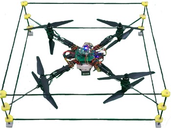
In this section, the experimental results of implementing the proposed control system for the octorotor in the presence of actuators fault and saturation are presented. Figure 4 shows the octorotor vertical flight system used for practical tests, and more practical details are presented in the following. The control system is designed and implemented by an ARM processor STM32f407. The sampling frequency of the system is 1000 Hz, and actuators are brushless DC motors (T-Motor Air Gear 350). In this system, the accelerometer sensor is used to measure the angular deviation of the system related to the horizon in the three-axis Cartesian coordinate system. This sensor comes with a gyro sensor (angular velocity around the axes) in the module (MPU6050). By combining these two sensors, a proper standard of deviation is obtained around each axis of coordinates. To measure the height, the SRF05 ultrasonic transducer is used whose range is 5–400 cm. The body and guard are made of carbon. Also, the vehicle mass was measured around
 $1.57$
kg, and the distance from the center of mass to the center of the propellers is
 $l=0.25$
m. The propellers were characterized using a force/torque sensor. The thrust and reaction torque coefficients were estimated as
 $\ K_f=3.2\times 10^{-5}\,{\rm Ns}^2/{\rm rad}^2$
and
 $K_t=7.2\times 10^{-7} {\rm Nm}/{\rm rad}^2 $
.
The experimental octorotor.

6.1. System identification and fault detection
Regarding (20), the inertia matrix which is used in the observer design should be estimated. As the angular velocities are obtained from the IMU and input signals are known, the inertia matrix is determined by using the recursive least squares (RLS) identification technique as follows:
 \begin{equation}{I_x} = 5.19\times 10^{-3} {\rm kg.m}^2\;\;\;\;\;\;\;,\;\;\;\;\;{I_y} = 5.18\times 10^{-3}\,{\rm kg.m}^2\;\;\;\;\;\;\;,\;\;\;\;\;\;{I_z} = 6.22\times 10^{-3}\,{\rm kg.m}^2\end{equation}
To verify the identification parameters, the actual system angular velocities are compared with the corresponding observed signals. Parameters of the observer are determined as
 $\ K_1=1.5$
,
 $\ K_2=1.5$
,
 $\ K_3=1.3$
,
 $\ K_4=1.1$
,
 $\ K_5=1.8$
, and
 $\ K_6=1.5$
. The results confirm the accuracy of the parameter identification as shown in Figs. 5 and 6. Also, the octorotor’s parameters are summarized in Table III.
Real and estimated angles and their residuals.

Real and estimated angular velocities and their residuals.

Ocotorotor’s parameters.

In order to simulate the occurrence of actuator fault, the M0 motor is suddenly turned off during the flight. Figures 5 and 6 show the actual and estimated roll, pitch, and yaw angles as well as their derivatives during normal flight, actuator failure, and the correction of the failure. Before the occurrence of the fault at sample 3514, the designed observer worked accurately. The behavior of the system and the observer start to deviate from each other as soon as one of the actuators fail, and as a result, the residuals begin to increase. The actuator fault is detected at sample 3767 when all the residuals reach their predefined thresholds. Based on the results of this experiment and the sampling time (
 $T_s = 0.001$
s), the fault was detected and corrected after 0.253 s. Also, as it was previously mentioned, the values of these thresholds affect the time interval of fault detection and the general performance of the observer.
After the fault detection, based on the sign of the angular velocities (
 $\dot{\phi} < 0,\dot{\theta} <0,\dot{\psi} <0 $
), it can be inferred that the M0 motor has failed during the flight. The fault detection unit produces
 $\textbf W(t)$
, such that
 $\ k_1(t) = 1 $
. Therefore, the fault tolerance unit (control allocation) can consider this damaged motor in the distribution of signals between the actuators.
As it was previously mentioned, in order to obtain the Euler angles an Inertial Measurement Unit or IMU is used in the designed octocoptor. IMUs have two key sensors, a gyroscope and an accelerometer. A gyroscope measures angular velocity, yet the integration of gyroscope measurement errors will lead to an accumulating error in the calculated orientation. Therefore, gyroscopes alone cannot provide an absolute measurement of orientation. An accelerometer can also provide the Euler angles rate in a different way. However, it is likely to be subject to high levels of noise which mostly is produced by vibration of motors’ rotation. As a result, in order to obtain accurate Euler angles in the presence of noise, the measurements of two sensors are combined based on the sensor fusion method proposed in ref. [Reference Madgwick38], and also a low-pass filter in used to get better results. The results are shown in Fig. 5. Additionally, in the control process, calculated noise-free Euler angles rather than their rates are used, which means noise does not interfere with the system’s control, and noise amplification does not occur.
Figure 6 shows filtered angular velocities which are generated by gyroscope. The effect of noise caused by motors vibration is inevitable, yet they can be used in the purpose of sliding mode observer without any problem. Note that in order to avoid delay in calculated Euler angles rates a sharp low-pass filter could not be used.
6.2. Fault tolerance and actuators saturation
As it has been previously mentioned, four virtual control signals that are produced by the main controllers should be converted to eight PWM signals by the control allocation unit. In this system, the minimum PWM signal is 45% for the motors to be turned on (minimum speed of the motors) and the maximum value is 100% (maximum speed of motors). However, in order to observe the saturation occurrence at altitudes below one meter for indoor tests, the maximum PWM value is set to 84%. It means that the actuators constraints are defined as
 $\ 45\% < u_i < 84\%$
. In order to examine the control system in the faulty situation, the M2 motor is turned off at an altitude about 25 cm. The fault is detected by the sliding mode observer, and as a result, distribution of the control signals are changed by the control allocation unit.
At first, the pseudo-inverse approach is used as the control allocation unit. Figure 7(a) shows the pitch, roll, and yaw angles after the fault occurrence, respectively. It is shown that, the angles oscillate between +10 and −10 degrees, the variance is about 8 degrees, and the system is on the verge of instability.
Octorotor angles (
 $\phi$
,
 $\theta$
, and
 $\psi$
).

In the second test, the pseudo-inverse along the null space (PAN) approach is employed as the control allocation unit. Figure 7(b) shows the results of this experiment. It is shown that the angles oscillate between +2 and −2 degrees, and the variance of the angles is about 0.5 degrees. In this method, after turning off a motor, the system provides an acceptable performance and remains stable.
In Table IV, the variances of the angles
 $\phi $
,
 $\theta $
, and
 $\psi $
are expressed for the applied control allocation methods. It is shown that the variance of the angles is decreased substantially in the second experiment.
Comparison variance of the system angles.

In both tests, the fourth output is the height that is very important for the flight system. As shown in Fig. 8(a), in the first test, height tracking is completely lost, and it has large oscillations. In the second test, the desired height tracking is achieved as is shown in Fig. 8(b). Also, the amplitude of oscillations is decreased significantly.
Octorotor height.

To investigate the causes of fluctuations and instability of the pseudo-inverse method, the desired PWM signals that are expected to be produced by the actuators (red line) and the actual PWM signal that the actuators could produce in the face of their practical limitation (blue line) are shown in Fig. 9. As it can be seen in Fig. 9, since the maximum PWM signal that each actuator can produce is 84%, the actual PWM signals are fixed at 84%, when the desired PWM signal exceeds this limitation. When the M2 motor is turned off, the M0, M1, and M5 motors demand control signals which are exceeded from their maximum values in most cases. But the PWM inputs of the motors cannot be more than 84%, so they are saturated. For example, according to Fig. 9, the control assignment of the M0 motor in the sample 20,000 expects to produce 100% PWM which is not applicable. Thus, the desired virtual control signals (
 $v_f$
) are not satisfied, which causes fluctuations in the outputs.
The pseudo-inverse method (the control signals of the actuators).

As is shown in Fig. 10, in the second experiment in which actuators’ saturations are considered, there is no discrepancy between the actuators control signal demands and the PWM inputs. In the face of failure of the M2 motor, the desired virtual control signals are redistributed among other correctly working actuators such that the actuators saturations do not degrade the control performance. In other words, the desired PWM signals (red line) can be produced by actuators (blue line), and they are completely matched.
The pseudo-inverse along the null space (the control signals of the actuators).

7. Conclusions
In this paper, the capabilities of the control allocation unit for a hovered octorotor are demonstrated in handling actuators failures and saturations by using practical experiments. It is observed that in the face of a faulty motor and motors saturations, the octorotor system will become unstable. To handle such situations, the PAN method is employed as the control allocation unit. The experimental results confirm that this approach can maintain closed-loop system stability and the height tracking properties in the face of fault or saturation occurrences.
Conflicts of Interest
None.
Financial Support
None.
Ethical Considerations
None.
Authors’ Contributions
None.