Introduction
Renewable energy harvesting is gaining importance for reducing reliance on conventional fossil fuel-based techniques. While large-scale installations are currently the main focus of the renewable energy sector, the trends in portable, wearable, and implantable electronic devices have opened up new opportunities in personal-scale energy harvesting. A variety of energy harvesting mechanisms have been proposed for this purpose, such as triboelectricity (energy harvesting from frictional contact), pyroelectricity (energy harvesting through changes in temperature), and piezoelectricity (harvesting energy through mechanical forces), among others.[Reference Wang, Zhu, Yang, Wang and Pan1–Reference Bowen, Kim, Weaver and Dunn3] Of the piezoelectric materials, polymers such as poly(vinylidene fluoride) (PVDF) have been previously reported to show high electromechanical coupling, biocompatibility,[Reference Li, Kang, Yu, Long, Jeffery, Cai and Wang4, Reference Yu, Sun, Orbay, Chen, England, Cai and Wang5] processability,[Reference Ramadan, Sameoto and Evoy6, Reference Martins, Lopes and Lanceros-Mendez7] optical transparency,[Reference Li, Katsouras, Piliego, Glasser, Lieberwirth, Blom and de Leeuw8] and mechanical flexibility,[Reference Bhavanasi, Kumar, Parida, Wang and Lee9] showing great promise in their utilization as flexible piezoelectric generators (PEGs).
PVDF is a semi-crystalline polymer, which is generally deposited into the symmetric and non-electroactive α phase using conventional polymer-compatible methods.[Reference Martins, Lopes and Lanceros-Mendez7, Reference Rajala, Schouten, Krijnen and Tuukkanen10] In this case, post-processing is undertaken to convert the α phase into the polar and highly electroactive β phase.[Reference Ramadan, Sameoto and Evoy6, Reference Bhavanasi, Kumar, Parida, Wang and Lee9]
In order to increase the β phase content in the polymer, the trifluoroethylene (TrFE) co-monomer can be introduced, which enables β phase formation due to the steric hindrance arising from the additional fluorine in the resultant PVDF-TrFE.[Reference Eberle, Schmidt and Eisenmenger11, Reference Soulestin, Ladmiral, Dos Santos and Ameduri12] The copolymer, with monomer ratios at 75 mol% VDF and 25 mol% TrFE, exhibits greater electromechanical coupling properties than the PVDF homopolymer.[Reference Martins, Lopes and Lanceros-Mendez7, Reference Rajala, Schouten, Krijnen and Tuukkanen10] PVDF-TrFE has been reported to show a thickness-axis piezoelectric charge coefficient d 33 = 38 pC/N (higher than PVDF d 33 = 28 pC/N) and a thickness-axis piezoelectric voltage coefficient g 33 = 380 mV m/N (PVDF g 33 = 320 mV/m/N).[Reference Ramadan, Sameoto and Evoy6, Reference Martins, Lopes and Lanceros-Mendez7, Reference Ito, Uchino and Chang13, Reference Chen, Ware, Baker, Chu, Hu and Sun14]
Under low-energy deposition conditions, the dipolar orientations in the β phase PVDF-TrFE are randomized, leading to a minimal net polarization vector. For the polymer to be utilized in PEGs, the dipoles are required to be aligned, or polarized, via a process referred to as poling.[Reference Ramadan, Sameoto and Evoy6] This method utilizes high temperatures coupled with high electric fields to preferentially align the dipole vector in a single direction. The harsh conditions of poling introduce several limitations, including the increased cost of manufacture, the lack of scalability, and the potential for electrical breakdown of the polymer.[Reference Ramadan, Sameoto and Evoy6, Reference Fortunato, Chandraiahgari, De Bellis, Ballirano, Sarto, Tamburrano and Sarto15] Hence, for the commercialization and scalable production of flexible fluoropolymer PEGs, the poling step should ultimately be a low-energy step, integrated into the deposition process. Previous reports have utilized electrospinning to simultaneously deposit and pole the PVDF-TrFE; however, the process still requires high electric fields and the intrinsic low feed volumes limit the scalability of this technique.[Reference Ghosh and Mandal16]
More recently, three-dimensional (3D) printing has been reported for the fabrication of electroactive fluoropolymer PEGs. Lee and Tarbutton[Reference Lee and Tarbutton17] have reported the use of electric poling-assisted melt 3D printing to simultaneously deposit and pole the PVDF homopolymer by applying an electric field up to 2 MV/m, generating 12 nC charge from the bending of the structure. Kim et al.[Reference Kim, Torres, Wu, Villagran, Lin and Tseng18] have utilized a similar method with electric fields up to 13 MV/m during 3D printing, generating 0.033 nC charge, which corresponds to d 33 = 0.048 pC/N.
Bodkhe et al.[Reference Bodkhe, Turcot, Gosselin and Therriault19] have reported a poling-free solvent evaporation-assisted (SEA) 3D-printed PVDF composite with a piezoelectric ceramic barium titanate nanoparticle filler (10 wt%) in the form of a 70-layer cylinder printed through a 100 µm internal diameter (ID) nozzle. The composite cylinder, printed at 20 mm/s x-y speed at 1 MPa pressure, is shown to generate up to 4 V from finger tapping in the 31-mode (electrodes deposited on the cylinder walls), with a calculated d 31 = 18 pC/N. This composite material is reported to fracture below 2 N of peak-to-peak force, an undesirable trait for a sustainable generator.
In the present work, SEA 3D printing was utilized to manufacture highly flexible and transparent PEGs from PVDF-TrFE under low-energy conditions. The shear-induced nozzle effects were investigated for the purpose of piezoelectric polymer polarization, and the effects of structured layer height on the resultant electrical output were analyzed.
Experimental
Materials
PVDF-TrFE powder (75 mol% VDF and 25 mol% TrFE, Solvay, Milan, Lombardy, Italy), acetone (AR grade, Chem-Supply Pty Ltd, Adelaide, South Australia, Australia) and N,N-dimethylformamide (DMF) (ACS Reagent, Sigma-Aldrich, St. Louis, Missouri, USA) were used without further purification.
3D printing
PVDF-TrFE powder was added to a solvent mixture consisting of acetone (60 vol%) and DMF (40 vol%) and magnetically stirred at 23 °C for the complete dissolution of the polymer into solution. For viscosity measurements, the PVDF-TrFE solutions were made at 20, 25, 30, 35, and 40 wt%. For 3D printing experiments, the 30 wt% solution was used. The PVDF-TrFE solution was transferred into a 30 mL dispensing barrel (Optimum, Nordson EFD, East Providence, Rhode Island, USA) through a 0.24 µm Teflon syringe filter (Millipore, St. Louis, Missouri, USA).
The PVDF-TrFE solutions were 3D printed on a pneumatically controlled dispensing system (3D-Bioplotter, EnvisionTEC, Gladbeck, North Rhine-Westphalia, Germany) through a 204 µm ID nozzle (SmoothFlow Tapered, Nordson EFD, East Providence, Rhode Island, USA) at 5 °C barrel temperature. The x-y speed was investigated between 5 and 45 mm/s. The extrusion pressure was set at 178 kPa.
A thin film layer acting as a substrate (layer zero) was first printed onto a clean glass substrate with total height and width set at 3 cm to obtain a total material area of 9 cm2, using a raster pattern with the width between lines at 400 µm. Consecutive layers (up to 19 layers) were then printed on top of the substrate thin film layer using a raster pattern with the width between lines set at 2 mm.
Characterization
Viscosity (η) characterization was carried out using a rheometer (MCR-702, Anton Paar, Graz, Styria, Austria) with cone-plate geometry (25 mm diameter, 2° angle). The measurements were taken at 5 °C by a continuous upwards ramp of the shear rate.
Optical properties of the 3D-printed PVDF-TrFE were measured using a UV-Visible-NIR system (Lambda 950, Perkin Elmer, Waltham, Massachusetts, USA) with an integrating sphere (150 mm diameter) at wavelengths between 780 and 380 nm with a resolution of 5 nm. Total luminous transmittance was reported as an average of the spectrum. Haze was measured in accordance with ASTM D1003 standard. The values reported were an average of measurements on three separate 3D-printed samples.
Helium ion beam microscopy (HIM) was utilized to characterize the cross-sectional morphology of the SEA 3D-printed PVDF-TrFE thin films and layered structures. The HIM micrographs were obtained using the Orion NanoFab (Carl Zeiss AG, Oberkochen, Baden-Wurttemberg, Germany), whereby the samples were sliced and adhered onto double-sided Cu tape on a cross-sectional holder.
For the determination of total electroactive (β + γ) phase fraction and confirming the absence of the non-electroactive α phase, attenuated total reflectance (ATR) Fourier transform infrared (FTIR) spectroscopy was used (Frontier, Perkin Elmer, Waltham, Massachusetts, USA). The absorbance was taken between 4000 and 600/cm with a resolution of 0.5/cm. The values reported for the fraction of electroactive phase (β + γ) were an average of measurements on three separate 3D-printed samples.
To measure the electrical output, PVDF-TrFE PEGs were fabricated by sputter coating (Q150T ES, Quorum, Lewes, East Sussex, UK) electrodes onto the top and bottom surfaces of the 3D-printed PVDF-TrFE. Sputtering consisted of a 2 nm coating of Cr to enhance adhesion, followed by a 10 nm coating of Au, masked to deposit a total electrode area of 2.8 cm2. Cu tape with attached wires was physically adhered onto each electrode. The voltage output of the 3D-printed PVDF-TrFE PEGs was measured using an oscilloscope (TDS 2002B, Tektronix, Beaverton, Oregon, USA) under cyclic compression (5943, Instron, Norwood, Massachusetts, USA) with a frequency of 5 Hz (parameters set at 400 mm/min speed and 50 N maximum force).
Results and discussion
The initial part of this study investigated suitable parameters for SEA 3D printing of PVDF-TrFE. For a fast setting material, the solvent must be volatile.[Reference Postiglione, Natale, Griffini, Levi and Turri20] Fluoropolymers such as PVDF and PVDF-TrFE are generally soluble in solvents with boiling point >100 °C, limiting their applications in SEA systems.[Reference Bottino, Capannelli, Munari and Turturro21] Acetone, a swelling agent of PVDF-TrFE, was added as a co-solvent with DMF, which can readily dissolve fluoropolymers. Conventionally, fluoropolymers are dissolved at a ratio of 80 vol% DMF and 20 vol% acetone, requiring high temperatures or long processing times to evaporate the solvent.[Reference Bodkhe, Turcot, Gosselin and Therriault19, Reference Yu and Cebe22] In the work presented here, a volume ratio of 60 vol% acetone relative to 40 vol% DMF was used after analysis of the solubility parameters, described in SI (Fig. S1).
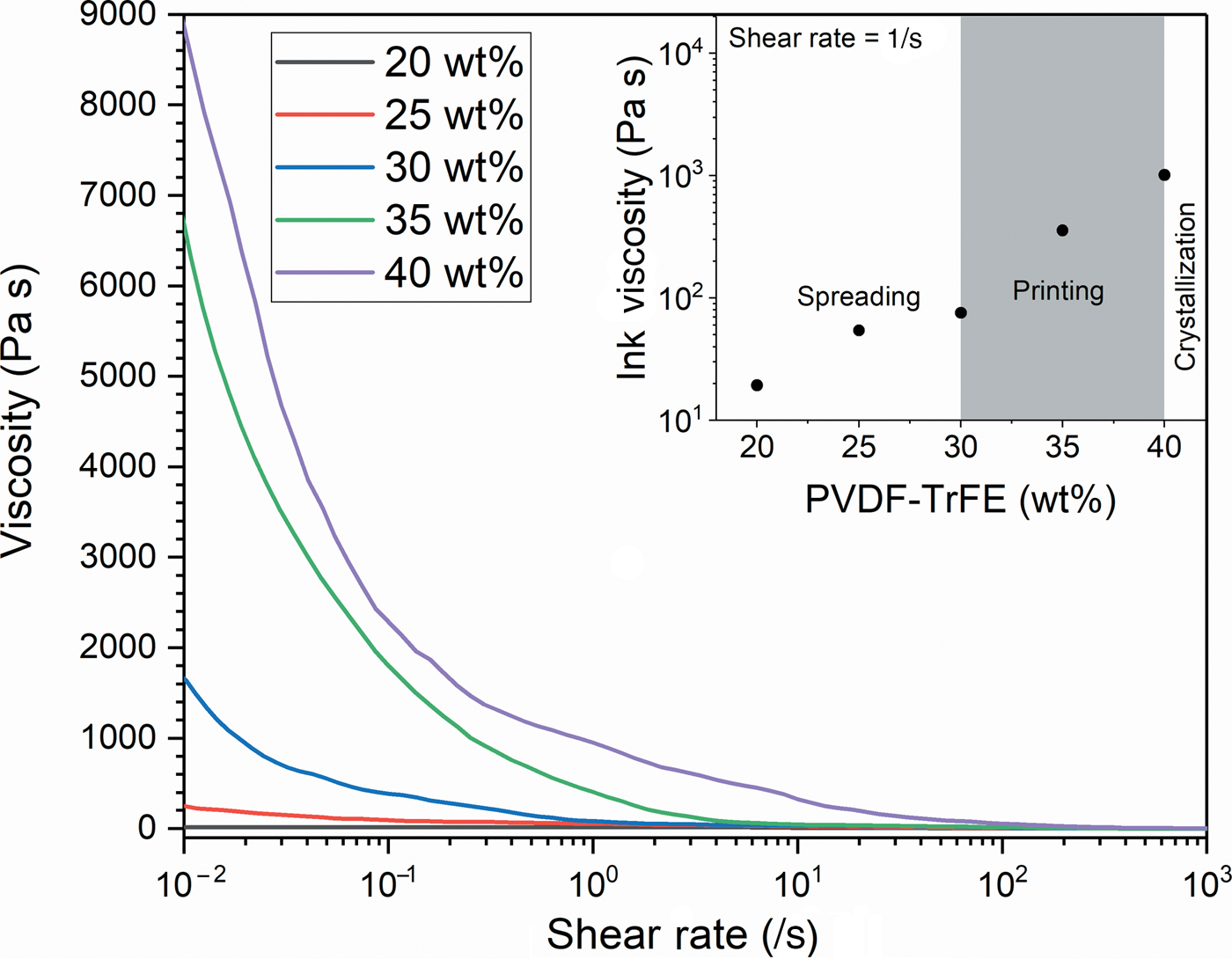
The flow behavior of PVDF-TrFE solutions was investigated via rheologic characterization. Figure 1 shows the dependence of the viscosity on the applied shear rate for the solutions with varying PVDF-TrFE loadings in acetone:DMF (60:40 vol%). A shear-thinning behavior was observed for all samples and the effect of PVDF-TrFE loading was significant. The viscosity of the PVDF-TrFE solutions was found to decrease with increasing shear rate, indicative of a non-Newtonian fluid.[Reference Murphy and Atala23] This type of rheologic behavior is ideal for 3D printing, as the solutions must be free-flowing (low viscosity) under the high shear stresses of the extrusion nozzle and consequently retain their shape (high viscosity) following extrusion.[Reference Ligon, Liska, Stampfl, Gurr and Mülhaupt24]
Viscosity of PVDF-TrFE solutions as a function of shear rate for PVDF-TrFE loadings between 20 and 40 wt%. Inset shows the viscosity at 1/s as a function of PVDF-TrFE loadings.

The viscosity at shear rates below 1/s was found to increase with increasing PVDF-TrFE loading, desirable for the printed structures to retain their shape post-deposition. The viscosity of the 20 wt% PVDF-TrFE solution (Fig. 1, black line) was relatively constant, between 20 and 10 Pa s up to a shear rate of 10/s, decreasing past 1 Pa s above 500/s shear rates (Fig. S2). The 25 wt% PVDF-TrFE solution (Fig. 1, red line) was found to exhibit shear thinning behavior throughout the investigated region. The viscosity at 0.01/s shear rate was 20 times higher than that of the 20 wt% solution, indicating greater shape retention and therefore higher printing resolution. Conversely, the viscosity was not found to decrease below 1 Pa s at up to 1000/s. The 30 wt% (Fig. 1, blue line) and 35 wt% (Fig. 1, green line) PVDF-TrFE solutions showed enhanced rheologic properties optimal for SEA 3D printing. The PVDF-TrFE solution containing 30 wt% exhibited an increase in viscosity of one order of magnitude over the 25 wt% solution at 0.01/s, decreasing to 0.11 Pa s at 1000/s shear rate. A more pronounced effect was seen in the 35 wt% PVDF-TrFE solution; however, it was noted that magnetic stirring alone was insufficient to completely dissolve the polymer. Therefore, the 30 wt% PVDF-TrFE in acetone:DMF (60:40 vol%) was used for further SEA 3D printing experiments.
The PVDF-TrFE solutions were subsequently 3D printed onto a clean glass substrate, consisting initially of a thin film layer as the substrate layer and consecutive structured layers. The temperature of the polymer solution was kept at 5 °C and the substrate at 23 °C.
The x-y speed of the robot head was optimized for greatest lateral resolution during printing, with the resulting structures shown optically in Fig. S3 and under an optical microscope in Fig. S4. At low speeds below 25 mm/s, the structures were found to be significantly wider than the nozzle ID, indicating low resolution of printing. Robot head speeds above 35 mm/s deposited structures with significantly lower width; however, loss of resolution at the squared corners was observed (Fig. S4). The structures with low width and high reproduction of desired shape were obtained at 30 mm/s printing and hence this speed was utilized for further printing.
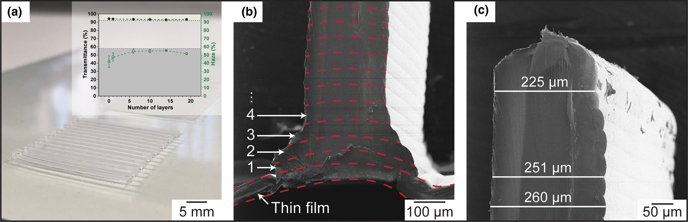
The substrate thin film layer was printed into a square with 3 cm width and height, following a raster pattern. The formation of the thin film was dependent upon successful binding of adjacent raster lines, hence the distance between the lines was varied to obtain a solid film with minimal thickness. The optimization of the initial thin film layer is shown in Fig. S5. At distances between raster lines >500 µm, the final structure resembled the input pattern. When the distance was set to 500 µm, a thin film was obtained, however the structure of the film was inconsistent. The formation of a thin film with no gaps is necessary for the fabrication of flexible PEGs, to ensure no short circuiting occurs between the electrodes. Consistent thin films were formed at a raster line distance of 400 µm, which resulted in films with approximately 40 µm thickness (Fig. S6). The SEA 3D-printed PVDF-TrFE thin films were transparent, with 94% total luminous transmittance (Fig. 2a, inset).
Morphology of 3D-printed PVDF-TrFE structures, showing (a) optical image of a 19-layer structure printed on top of a thin film, with the inset showing transmittance and haze as a function of layers deposited, (b) cross-sectional HIM image of the thin film and subsequent layers deposited and (c) cross-sectional HIM image of the top of a 19-layer PVDF-TrFE structure.

Following the printing of the initial PVDF-TrFE thin film layer, structures were deposited in a layer-by-layer manner up to 19 layers. Figure 2a shows an optical image of a 19-layer PVDF-TrFE raster structure on top of a printed thin film layer. The structures are free-standing and self-supporting, retaining their shape when removed from the glass substrate. The 3D-printed PVDF-TrFE structures were found to be transparent at up to 19 layers (Fig. 2a, inset), with total luminous transmittance above 92% and haze below 58% in all samples.
The cross-sectional HIM analysis of the thin film and the initial structured layers is shown in Fig. 2b. The image shows the solid internal nature of the structures, confirming the complete evaporation of the solvents. Furthermore, the initial layers printed on top of the PVDF-TrFE thin film exhibited broadening of the structures, likely explained by enhanced compatibility of the PVDF-TrFE solution and the previous deposited layer, as well as the minimization of liquid–air interfacial surface area. Figure 2c shows the cross-sectional HIM image of the top of a 19-layer 3D-printed PVDF-TrFE structure. The maximum width of the structures was found to be 260 µm, corresponding to 27% broadening relative to the nozzle ID. The final layer had a width of 225 µm, corresponding to 10% broadening and suggesting near-optimal printability of the 30 wt% PVDF-TrFE solutions in acetone:DMF (60:40 vol%).
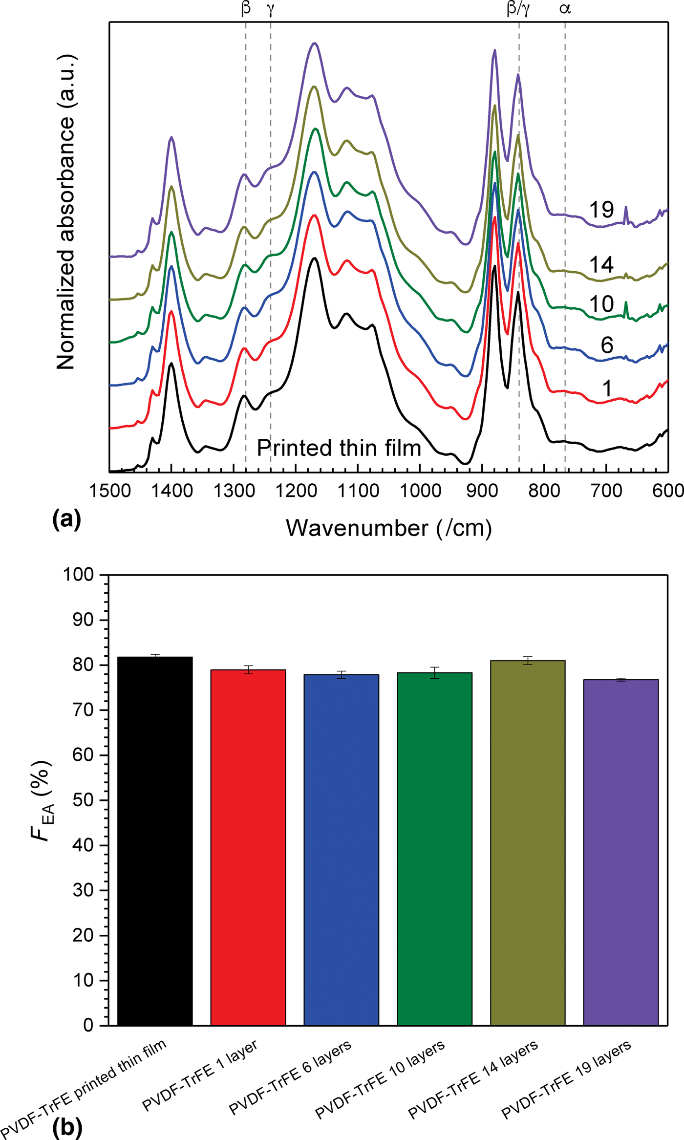
In order to obtain highly efficient fluoropolymer PEGs, it is necessary to maximize the content of electroactive phases (consisting of the highly polar β phase and semi-polar γ phase), which is often characterized using FTIR.[Reference Cai, Lei, Sun and Lin25] Figure 3a shows the ATR-FTIR spectra in the region of interest between 1500 and 600/cm for the SEA 3D-printed PVDF-TrFE structures on printed thin films as a function of the number of layers. The peak at 840/cm in all samples is indicative of the presence of the electroactive phase consisting of the β and γ phases.[Reference Martins, Lopes and Lanceros-Mendez7] The secondary contributing peaks at 1280 and 1240/cm were representative of the presence of the β and γ phases, respectively.[Reference Barrau, Ferri, Da Costa, Defebvin, Leroy, Desfeux and Lefebvre26] The prominent presence of the secondary β phase peak was found in all samples, whereas the secondary γ peak was found as a shoulder. Moreover, the absence of pronounced peaks at 766/cm, generally correlated to the non-polar crystalline α phase in fluoropolymers, indicates that the SEA 3D-printed PVDF-TrFE structures were deposited directly into the electroactive phases through low-temperature printing.
ATR-FTIR characterization of SEA 3D-printed PVDF-TrFE materials, (a) the FTIR spectra in the fingerprinting region as a function of the number of printed layers (offset for clarity) and (b) the calculated F EA as a function of the number of printed layers.

The fraction of total electroactive phase F EA was quantified through Eq. (1), shown as a function of the number of layers in Fig. 3b.[Reference Cai, Lei, Sun and Lin25, Reference Barrau, Ferri, Da Costa, Defebvin, Leroy, Desfeux and Lefebvre26] Here, I EA corresponds to the intensity of the peak at 840/cm, I α corresponds to the intensity of the peak at 766/cm, and K EA and K α correspond to the absorption coefficients at the respective wavenumbers, given as 6.1 × 10⁴ and 7.7 × 10⁴/cm2/mol, respectively.[Reference Gregorio and Cestari27]
 $$F_{{\rm EA}} = \displaystyle{{I_{{\rm EA}}} \over {\lpar {K_{{\rm EA}}/K_\alpha} \rpar I_\alpha + I_{{\rm EA}}}}.$$
The F EA (shown in Fig. 3b) of the 3D-printed PVDF-TrFE thin films was 81.7%, which is significantly higher than that of the PVDF homopolymer when processed using low-energy methods.[Reference Barrau, Ferri, Da Costa, Defebvin, Leroy, Desfeux and Lefebvre26] Three-dimensional printing of PVDF-TrFE structures on top of the printed thin film layer resulted in a slight decrease of F EA to 79.0%, attributed to the increasing interfacial area between the solution and surrounding air. Additional layer-by-layer deposition of structures decreased the F EA to a minimum 76.8% at 19 3D-printed layers of PVDF-TrFE. These decreases were not considered significant, as the contributions in Fig. 3a from β (1280/cm) and γ (1240/cm) were present throughout the entire printing process.
The energy harvesting capability was quantified for PEGs fabricated using the SEA 3D-printed PVDF-TrFE. In general, PVDF-TrFE PEGs prepared via solvent evaporation techniques such as drop casting and solvent casting show a randomized directionality for the polarization vector, inhibiting electromechanical conversion and showing no electrical output upon deformation without poling.[Reference Bhavanasi, Kumar, Parida, Wang and Lee9] Hence, to be electroactive, the piezoelectric polymer is generally required to be poled via highly energetic methods. However, in this work, we investigated the electrical output of the 3D-printed layers, which have not been exposed to any conventional poling techniques in order to ascertain if shear alone would enhance the output, building on previous modeling[Reference Yang, Ryu, Lansac, Jang and Lee28] and rheology[Reference Gebrekrstos, Sharma, Madras and Bose29] studies.
Here, the SEA 3D-printed PVDF-TrFE samples were coated with two conductive materials on each side through a shadow mask, consisting of a 2 nm Cr layer, acting as a seeding and adhesion layer, and a 10 nm Au layer. The sputter-coated electrode covered the entire surface on each side, both the bottom of the substrate layer and the top of the structure and substrate, including the walls of the structures. Wires were soldered to Cu tape and physically adhered to the coated electrodes. The PVDF-TrFE with electrodes was then encapsulated with insulating polyimide (Kapton) tape to prevent external influences on the electrical output. The resulting SEA 3D-printed PVDF-TrFE PEGs with a varying number or layers were investigated for their electroactivity upon mechanical compression. An Instron was used in cyclic compression mode to induce deformation. The open circuit voltage (V OC) was measured concurrently by an oscilloscope.
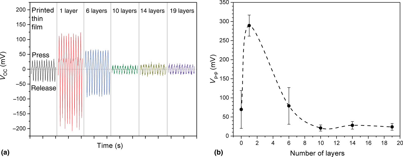
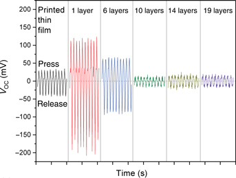
Figure 4a shows the representative V OC as a function of time for the increasing number of layers in the SEA 3D-printed PVDF-TrFE PEGs. Initially, it was found that the 3D-printed thin film was able to generate electricity upon cyclic deformation, which does not occur in other low-energy deposition techniques.[Reference Bhavanasi, Kumar, Parida, Wang and Lee9] The 3D-printed PVDF-TrFE thin film PEG generated an average peak-to-peak voltage (V p−p) of 69.6 ± 49.6 mV (Fig. 4b), exhibiting electroactivity.
(a) Representative open circuit voltage for SEA 3D-printed PVDF-TrFE PEGs as a function of time under 5 Hz cyclic compression. The positive peaks represent increasing compressive force, whereas negative peaks represent decreasing compressive force. Each division on the time axis represents 1 s and (b) peak-to-peak voltage output of the PEGs as a function of the number of 3D-printed structured layers of PVDF-TrFE. The first data point represents a 3D-printed thin film. Error bars were obtained using the maxima and minima of 50 compression cycles, for three separate samples per data point.

The PEG samples consisting of one structured layer 3D printed onto the printed thin film layer were found to generate the highest voltage. The average V p−p of the one-layer samples was 289.3 ± 27.6 mV, a fourfold increase over that of the thin film printed PEG. This was attributed to the increased aspect ratio and surface area of the material compared with the printed thin film PEG. As noted in the ATR-FTIR results, there is not a great change in the F EA %; therefore, it is proposed that this increase in electrical output for the one layer is primarily due to shear-induced polarization at the 3D printing nozzle walls.[Reference Yang, Ryu, Lansac, Jang and Lee28, Reference Gebrekrstos, Sharma, Madras and Bose29]
By further increasing the number of layers that were 3D printed on top of the thin film, a decrease in the V p−p output from cyclic compression to background levels was observed. This phenomenon was attributed to the spatial distribution of the electrode. The sputter coating technique deposits the electrode on the walls of the 3D-printed PVDF-TrFE structures, negating further enhancements in electroactivity at higher layer numbers.
Conclusion
In summary, SEA 3D printing was used to manufacture flexible and transparent PVDF-TrFE PEGs and the effects of utilizing a shear-enhanced deposition technique were investigated. The visible-wavelength transmittance for the 3D-printed PVDF-TrFE was above 92% for all samples, up to 19 layers on a thin film. The electroactive (β + γ) phase fraction showed values between 75% and 80% for all samples. The 3D-printed thin film PVDF-TrFE PEG exhibited 69.6 mV peak-to-peak voltage, increasing to a maximum of 289.3 mV in the generator consisting of one structured layer printed on top of the thin film. This increased output was proposed to be due to shear-induced polarization—not related to an increase in β phase. Overall, the SEA 3D printing technique shows great promise in producing enhanced electrical output from fluoropolymer-based PEGs through low-temperature and low-energy deposition methods.
Supplementary material
The supplementary material for this article can be found at https://doi.org/10.1557/mrc.2019.19.
Acknowledgments
This research was supported by the Australian Government through the Australian Research Council's Linkage Projects funding scheme (LP160100071) and Future Fellowships funding scheme (FT130100211). This work was performed in part at the Materials Characterisation and Fabrication Platform (MCFP) at the University of Melbourne and the Victorian Node of the Australian National Fabrication Facility (ANFF).