1. Introduction
With the expansion of the robotic application area, precise trajectories of a robot manipulator are required through off-line programming in more and more situations, in which the pose (position and orientation) accuracy is one of the major concerns [Reference Yang, Wu, Li and Chen1]. Due to inherent kinematic errors such as manufacturing error, assembly error, wear and tear, the actual poses of serial robots will deviate from their desired ones. As a consequence, serial robots could hardly achieve the specified pose precision to perform tasks. Thus, kinematic calibration is usually carried out as an effective and economical way for enhancing the absolute pose accuracy of serial robots.
Kinematic calibration has attracted numerous researcher’s interests since the 1980s [Reference Zhuang and Roth2], which consists of four major steps: kinematic modeling, pose or position measurement, kinematic parameter identification, and parameter error compensation [Reference Roth, Mooring and Ravani3]. This paper mainly pays attention to kinematic modeling and kinematic parameter identification issues. A literature review reveals that lots of kinematic modeling methods have been developed, and most of the existing models involve redundant parameters. As redundancy may affect the robustness of kinematic parameter identification [Reference Meggiolaro and Dubowsky4], the parametric minimality, meaning that the model has no redundant parameters, is defined as the third property for evaluating parameters of an optimum kinematic model, besides its continuity and completeness [Reference Schröer, Albright and Grethlein5]. The classical Denavit–Hartenberg
 $\left(\rm DH\right)$
model [Reference Denavit and Hartenberg6] with minimal kinematic parameters is widely used in the robotic kinematics, but it lacks continuity because there exists the singularity problem when the axes of two consecutive joints are nearly parallel or parallel. To meet the requirement of parametric continuity, a variety of modified models have been successively produced, including the modified Denavit–Hartenberg
 $\left(\rm MDH\right)$
model [Reference Hayati7], the complete and parametrically continuous
 $\left(\rm CPC\right)$
model [Reference Zhuang, Roth and Hamano8], and the S-model [Reference Stone and Sanderson9]. However, there have to introduce redundant parameters in all the above-mentioned models, resulting in more intricate modeling processes.
The exponential map between a neighborhood of the identity of Lie group and a neighborhood zero of Lie algebra is regarded as a diffeomorphism owing to the exponential map from a Lie algebra to a Lie group is smooth and its derivative at the identity is identical [Reference Murray, Li and Sastry10]. Thus, another idea of kinematic modeling is based on the POE formula. Park and Okamura [Reference Okamura and Park11] first introduced the POE formula to the kinematic calibration of serial robots, and the differentials of the exponential map at joint twists were presented in the definite-integral form. Chen et al. [Reference Chen, Yang, Tan and Yeo12] proposed the Local POE
 $\left(\rm LPOE\right)$
-based error model for robotic kinematic calibration, which only involves the error in the initial pose of the consecutive local frames. However, the exponential terms of error parameters are introduced in the process of updating kinematic parameters, leading to the complicated update process and nonintuitive physical meaning. On the basis of the original POE-based calibration model, Lou et al. [Reference Lou, Chen, Wu, Li and Jiang13] pointed out that the joint offset errors are converted into the twist errors, and put forward an improved calibration model, which still includes the aforementioned definite integrals. Subsequently, He et al. [Reference He, Zhao and Yang14] gave explicit expressions for the POE-based kinematic calibration of serial robots. Whereas each joint twist has to be normalized and orthogonalized at the end of each iteration step to meet the joint constraint conditions, which not only reduces the accuracy of the calibration result but also may affect the stability of the calibration process. In order to avoid the process of normalization and orthogonalization, Gao et al. [Reference Gao, Wang, Jiang and Pan15] given the POE-based explicit calibration approach of serial robots by using the adjoint transformation. In order to simplify the method of updating kinematic parameters, Jiang et al. [Reference Jiang, Gao and Yu16] modified the adjoint error model and proposed an improved robot kinematic calibration method based on the POE formula.
In contrast to the vast amount of literature review concerning the POE-based or Local POE-based methods for the calibration of serial robots, there are only a few methods that simultaneously meet the requirements of parametric minimality, continuity, and completeness.[Reference Wang, Wang and Yun17–Reference Sun, Lian, Yang and Song23] Wang et al. [Reference Wang, Wang and Yun17] presented the POE-based calibration approach of kinematic parameters for serial robots, which only need to identify five independent parameters for a revolute joint, including four independent parameters of the joint twist coordinate and one joint displacement. As the redundant parameters are eliminated by directly utilizing the joint geometrical constraints, the joint twist coordinate error descriptions are inconsistent, leading to the complicated identification procedure of the kinematic parameters. Additionally, Yang et al. [Reference Yang, Wu, Li and Chen1,Reference Wu, Yang, Chen and Ren18] argued that constant pitch and unit norm constraints of the twists have no effects to the geometric error accumulations and put forward the POE-based error model for the minimal kinematic parameter calibration of serial robots by establishing a set of link frames. The number of identifiable kinematic parameters is
 $5r+3p+6$
in their calibration approach, where r and p denote the quantities of equivalent revolute and prismatic joints, respectively. On the basis of the original LPOE-based calibration model, Chen et al. [Reference Chen, Wang and Lin19] established a reformulated local POE model
 $\left(\rm RLPOE\right)$
by an additive error updates and proved that the maximum identifiable error parameters of a serial robot were
 $4r+2p+6$
. Li et al. [Reference Li, Wu, Löwe and Li20] gave a robot kinematic calibration algorithm by the adjoint error model in the axis configuration space based on the POE formula, in which the same conclusion was drawn as in ref.[r19]. Subsequently, Chang et al. [Reference Chang, Liu, Ni and Qi21] proposed the POE-based improved kinematic calibration approach, where the tool frame is selected as the reference frame and the joint offset errors are converted into the twist errors. However, this calibration method lacks universality owing to it is not suited for the situation when the direction of the joint twist axis is opposite to the Z-axis of the base frame. Sun et al. [Reference Sun, Lian, Yang and Song23] presented the kinematic calibration method of serial robots by finite and instantaneous screw
 $\left(\rm FIS\right)$
theory. Meanwhile, the maximum independent error parameters of serial robots were also proved to be
 $4r+2p+6$
in this calibration method. Therefore, for the conventional serial robots, a consensus has been reached about the issue of minimality. Recently, the POE-based method with complete, minimal, and continuous error models has been successfully extended to the kinematic calibration of parallel robots. [Reference Sun, Lian, Yang and Song23–Reference Kong, Chen, Wu, Huang and Zhang25]
Since the orientation and position data are put together to formulate the cost function in most POE-based calibration methods of serial robots mentioned above, one will have to carefully consider the matching between the scales of the orientation data and position data, so as to need to add a weight matrix to the cost function to seek a balance between these two kinds of variables, but it is not easy to determine the best weight.[Reference Wu, Yang, Chen and Ren18] In this article, we present an improved minimal kinematic calibration algorithm of serial robots based on the POE formula. On the one hand, the unified minimal error model is established as the initial pose error is defined in the tool frame and all twist descriptions is consistent. On the other hand, a novel identification method is put forward to avoid considering the matching between the scales of the orientation data and position data and determining the best weight. The remaining sections of this paper are well ordered as follows: Section II gives the unified forward kinematics. Section III derives the corresponding minimal error model and proposes a novel parameter identification method. Section IV verifies the effectiveness of the proposed calibration algorithm by the simulation and experiment studies on the different serial robots. Finally, the brief conclusion is drawn in Section V, where the advantages of the algorithm are described.
2. Kinematic Modeling
2.1. Forward kinematics based on POE formula
The forward kinematics for an n-degree-of-freedom
 $\left(\rm DOF\right)$
serial robot based on the POE formula only require two coordinate frames, the base coordinate frame
 $\left\{\rm S\right\}$
and tool coordinate frame
 $\left\{\rm T\right\}$
attached to the robot base and end-effector, respectively, as shown in Fig. 1. Thus, the forward kinematics for an n-DOF serial robot containing either revolute or prismatic joints can be written as [Reference Okamura and Park11]
 $\begin{equation}\begin{aligned}{{{f}}}_{st}\left({{{q}}}\right) = {e^{{{\hat{\boldsymbol \xi}}_{1}}{q_{1}}}} {e^{{{\hat{\boldsymbol \xi}} _ {{2}}} {q_{2}}}} \cdot\cdot\cdot {e^{{{\hat{\boldsymbol{\boldsymbol \xi}}}_{{i}}}{q_{i}}}} \cdot\cdot\cdot {e^{{{\hat{\boldsymbol \xi}}_{n}}{q_{n}}}}{{{{f}}}_{st}} \left(0\right)\end{aligned}\end{equation}$
where
 ${{{f}}}_{st}\left({{{q}}}\right)$
is the pose matrix at the frame
 $\left\{\rm T\right\}$
shown in the frame
 $\left\{\rm S\right\}$
,
 $\hat{\boldsymbol \xi}_{i}$
is the twist associated with the ith joint,
 ${q}_{i}$
is the ith joint displacement,
 ${{{f}}}_{st}\left(0\right)$
is the initial pose matrix of the frame
 $\left\{\rm T\right\}$
with respect to the frame
 $\left\{\rm S\right\}$
while the robot is in the reference configuration.
An n-DOF serial robot.

Here, note that all vectors in the direction of joint motion and points on the joint axis are specified in the frame
 $\left\{\rm S\right\}$
. Hence, the ith joint twist
 $\hat{\boldsymbol \xi}_{i}$
can be written as[Reference Okamura and Park11]
 $\begin{equation}\begin{aligned}\hat{\boldsymbol \xi}_{i}=\begin{bmatrix} {\hat{\boldsymbol \omega}_{i}}&{{{p}}}_{i} \times {\boldsymbol \omega}_{i}\\ \\[-7pt] \boldsymbol 0 & 0 \end{bmatrix}=\begin{bmatrix} {\hat{\boldsymbol \omega}_{i}}&{{{v}}}_{i}\\ \\[-7pt] \boldsymbol 0 & 0 \end{bmatrix}\end{aligned}\end{equation}$
and the joint twist can be expressed as a six-dimensional vector through a mapping, termed the joint twist coordinate.[Reference Okamura and Park11] Therefore, the ith joint twist coordinate denoted by
 ${\boldsymbol \xi}_{i}$
can be expressed as
 $\begin{equation}\begin{aligned}\boldsymbol \xi_{i} ={{\left[ \begin{matrix} {\hat{\boldsymbol \omega }_{i}} & {{{v}}}_{i} \\ \\[-7pt] \boldsymbol 0 & 0 \\ \end{matrix} \right]}^{\vee }}=\left[ \begin{matrix}\boldsymbol \omega_{i} \\ \\[-7pt] {{{v}}}_{i} \\\end{matrix} \right]\end{aligned}\end{equation}$
where
 ${{{p}}}_{i}\in \Re^{3\times1}$
is a position vector locating any point on the ith joint twist axis,
 $\boldsymbol{\omega}_{i}=\begin{bmatrix} \omega_{ix}, \omega_{iy}, \omega_{iz} \end{bmatrix}^{\rm T}\in \Re^{3\times1}$
is a unit vector in the direction of the ith joint twist axis, and
 $\hat{\boldsymbol{\omega}}_{i}\in so\left(3\right)$
is
 $3\times3$
skew-symmetric matrix of
 $\boldsymbol{\omega}_{i}$
, such that
 $\begin{equation*}\begin{aligned} \hat{\boldsymbol{\omega}}_{i}=\begin{bmatrix} 0 & -\omega_{iz} & \omega_{iy} \\ \\[-7pt] \omega_{iz} & 0 & \omega_{ix} \\ \\[-7pt] -\omega_{iy} & \omega_{ix} & 0 \end{bmatrix}\end{aligned}\end{equation*}$
By introducing
 $\hat{\boldsymbol \xi}_{st}$
as the initial transformation twist,
 $\,{{{f}}}_{st}\left(0\right)$
can be given in a form of the exponential map as [Reference Okamura and Park11]
 $\begin{equation}\begin{aligned}{{{{f}}}_{st}} \left(0\right)={e^{{{\hat{\boldsymbol \xi}}_{st}}}}={{\left[\begin{matrix} {{{R}}}_{st} & {{{p}}}_{st} \\ \\[-7pt] \boldsymbol 0 & 1 \\ \end{matrix}\right]}}\end{aligned}\end{equation}$
Where the initial transformation twist can be expressed as [Reference Okamura and Park11,Reference Chen, Yang, Tan and Yeo12]
 $\begin{equation}\begin{aligned}{\hat{\boldsymbol \xi}_{st}}={\rm log{\left[\begin{matrix} {{{{R}}} }_{st} & {{{p}}}_{st} \\\\[-7pt] \boldsymbol 0 & 1 \\ \end{matrix}\right]}}={{\left[ \begin{matrix} \hat{\boldsymbol \omega }_{st} & {{{A}}}^{-1} {{{p}}}_{st} \\ \\[-7pt]\boldsymbol 0 & 0 \\ \end{matrix} \right]}}\end{aligned}\end{equation}$
In terms of Eq. (4), the aforementioned forward kinematics based on the POE formula can be rewritten as:
 $\begin{equation}\begin{aligned}{{{f}}}_{st}\left({{{q}}}\right) = {e^{{{\hat{\boldsymbol \xi}}_{1}}{q_{1}}}} {e^{{{\hat{\boldsymbol \xi}}_{{2}}} {q_{2}}}} \cdot\cdot\cdot {e^{{{\hat{\boldsymbol{\boldsymbol \xi}}}_{{i}}}{q_{i}}}} \cdot\cdot\cdot {e^{{{\hat{\boldsymbol \xi}}_{n}}{q_{n}}}}{e^{{{\hat{\boldsymbol \xi}}_{st}}}}\end{aligned}\end{equation}$
2.2. Improved forward kinematics
2.2.1. Auxiliary frame introduction
Reference [Reference Evertt and Hsu26] indicated that the maximum number of identifiable kinematic parameters is
 $4r+2p+6$
when the joint displacement errors are not considered, in which r and p denote the quantities of equivalent revolute and prismatic joints, respectively. In our study, the redundant parameters are eliminated by introducing an auxiliary frame based on each joint axis that also simplifies the expression of the joint twist coordinates. The auxiliary frame
 $\left\{i\right\}$
is followed the rules below.[Reference Yang, Wu, Li and Chen1,Reference Li, Wu, Löwe and Li20]
For the ith revolute joint (see Fig. 2): the axis of the ith revolute joint is set as the Z-axis of the auxiliary frame
 $\left\{i\right\}$
. If the
 $Z_i$
-axis has not pass through the origin of the frame
 $\left\{\rm S\right\}$
, the origin
 $O_i$
of the auxiliary frame
 $\left\{i\right\}$
is viewed as the intersection of the axis with a plane that is perpendicular to the axis and passes through the origin of the frame
 $\left\{\rm S\right\}$
. The unit vector along
 ${{{p}}}_i$
was represented as the
 $Y_i$
-axis, and
 $X_i$
-axis can be determined by the right-hand rule. Hence, the homogenous transformation matrix is expressed as
 $\begin{equation}{{{g}}}_i = \begin{bmatrix} \frac{{{{v}}}_i}{\left\|{{{v}}}_i\right\|} & \frac{{{{p}}}_i}{\left\|{{{p}}}_i\right\|} & \boldsymbol{\omega}_i & {{{p}}}_i\\\\[-7pt] 0 & 0 & 0 & 1\end{bmatrix}\end{equation}$
Auxiliary frame.

If the vector
 ${{{p}}}_i$
is a zero vector, the
 $Z_i$
-axis pass through the origin of the frame
 $\left\{\rm S\right\}$
. Then, we introduce the vector
 ${{{r}}}_i=\left[0,0,1\right]^{\rm T} \times \boldsymbol{\omega}_i$
as the rotation axis and obtain the auxiliary frame
 $\left\{i\right\}$
by rotating the frame
 $\left\{\rm S\right\}$
about
 ${{{r}}}_i$
for
 $\alpha_i=\arccos\left(\left[0,0,1\right]\boldsymbol{\omega}_i\right)$
. The homogenous transformation matrix of the auxiliary frame
 $\left\{i\right\}$
relative to the frame
 $\left\{\rm S\right\}$
can be given by
 $\begin{equation}{{{g}}}_i = \begin{bmatrix} \boldsymbol{\rm I}_3+\hat{{{{r}}}}_{i} \sin\left(\alpha_{i}\right)+\hat{{{{r}}}}^2_{i} \left(1-cos\left(\alpha_{i}\right)\right) & \boldsymbol{0}^{\rm T}\\ \boldsymbol{0} & 1\end{bmatrix}\end{equation}$
where
 $\hat{{{{e}}}}_{i}$
is the anti-symmetric matrix of the vector
 ${{{e}}}_i$
. If
 $\boldsymbol{\omega}_i$
is coincident with the Z-zxis of the frame
 $\left\{\rm S\right\}$
,
 ${{{g}}}_i$
is the unit matrix. If
 $\boldsymbol{\omega}_i$
is opposite to the Z-zxis of the frame
 $\left\{\rm S\right\}$
,
 ${{{g}}}_i$
can be regarded as the frame
 $\left\{\rm S\right\}$
rotated about the X-zxis for
 $\pi$
.
For the ith prismatic joint: the axis of the ith prismatic joint is set as the Z-axis of the auxiliary frame
 $\left\{i\right\}$
. The origin of the auxiliary frame
 $\left\{i\right\}$
can be set the same as the frame
 $\left\{\rm S\right\}$
, and the rest is defined in the same way as the revolute joint whose axis pass through the origin of the frame
 $\left\{\rm S\right\}$
, except for replacing
 $\boldsymbol{\omega}_i$
with
 ${{{v}}}_i$
.
2.2.2 Adjoint transformation
 $\boldsymbol{\zeta}_i=\left[{{\boldsymbol{\omega}}^{\prime}_i}^{\rm T},{{{{{v}}}}^{\prime}_i}^{\rm T}\right]^{\rm T}$
is denoted as the twist coordinate of ith joint in the auxiliary frame, as shown in Fig.
 $3\left(a\right)$
. Then the corresponding joint twist coordinate in the base frame can be represented by the adjoint transformation of
 ${{{g}}}_i$
 $\left(for \ further \ details, \ see \ Appendix \ A\right)$
. Thus, we can establish the relationship between
 $\boldsymbol{\zeta}_i$
and
 $\boldsymbol{\xi}_i$
as follows:
 $\begin{equation}\begin{aligned} \boldsymbol{\xi}_i=Ad\left({{{g}}}_i\right) \boldsymbol{\zeta}_i\end{aligned}\end{equation}$
Here, the ith joint twist coordinate in the auxiliary frame is expressed as
For the revolute joint:
 $\boldsymbol{\zeta}_i=\left[ 0, 0, 1, 0, 0, 0\right]^{\rm T}$
;
For the prismatic joint:
 $\boldsymbol{\zeta}_i=\left[ 0, 0, 0, 0, 0, 1\right]^{\rm T}$
.
2.2.3. Actual kinematics establishment
Due to inherent kinematic errors as mentioned above, the actual kinematic parameters of serial robots, which include the joint twists, the joint displacements and the initial pose, will always deviate from their nominal ones. Meanwhile, refs. [Reference Lou, Chen, Wu, Li and Jiang13 and Reference Gao, Wang, Jiang and Pan15] indicated that the joint displacements retain the nominal values when their errors are regarded as part of the twist errors. Thus, we just need to identify the joint twist and initial pose errors. As can be seen from the previous analysis, the actual joint twist coordinates
 $\boldsymbol{\zeta}^a$
are determined by the
 ${\boldsymbol{\omega}^{\prime a}}$
and
 ${{{{p}}}^{\prime a}}$
for the revolute joints. Due to the
 $\boldsymbol{\omega}^{\prime a}$
is always a unit vector, only two independent parameters are needed that can be denoted by
 ${\omega}^{\prime a}_x$
and
 ${\omega}^{\prime a}_y$
, respectively. According to Fig.
 $3\left(a\right)$
, we can choose an intersection point of the actual joint axis and plane
 $X-Y$
in the auxiliary frame, which can be denoted by
 ${{{{p}}}^{\prime a}}=\left[{p}^{\prime a}_x,{p}^{\prime a}_y,0\right]^{\rm T}$
, due to it can be an arbitrary point along the actual joint axis. Therefore, the actual twist coordinate of the ith revolute joint can be written as follows:
 $\begin{equation}\boldsymbol{\zeta}^a_i\left(\boldsymbol{\eta}_i\right) =\begin{bmatrix} {\boldsymbol{\omega}}^{\prime a}_i\\ \\[-7pt] {{{{v}}}}^{\prime a}_i\end{bmatrix}=\begin{bmatrix} {\boldsymbol{\omega}}^{\prime a}_i\\ \\[-7pt] {{{{p}}}}^{\prime a}_i \times {\boldsymbol{\omega}}^{\prime a}_i\end{bmatrix}={{{B}}}_i \boldsymbol{\eta}_i \end{equation}$
where
 $\boldsymbol{\eta}_i=\left[{{\omega}}^{\prime a}_{ix},{{\omega}}^{\prime a}_{iy},{p}^{\prime a}_{ix},{p}^{\prime a}_{iy}\right]^{\rm T}$
is the MP of twist coordinate for the ith revolute joint,
 ${{{B}}}_i$
is the transformation matrix which maps
 $\boldsymbol{\eta}_i$
into
 $\boldsymbol{\zeta}^a_i$
.
Similarly, we can define
 $\boldsymbol{\eta}_i=\left[{v}^{\prime a}_{ix},{v}^{\prime a}_{iy}\right]^{\rm T}$
as the MP of twist coordinate for the ith prismatic joint because of it is always a unit vector. Hence, the actual twist coordinate of the ith prismatic joint can be written as follows:
 $\begin{equation}\boldsymbol{\zeta}^a_i\left(\boldsymbol{\eta}_i\right)=\begin{bmatrix} \boldsymbol{0}^{\rm T}\\\\[-7pt] {{{{v}}}}^{\prime a}_i\end{bmatrix}={{{B}}}_i \boldsymbol{\eta}_i \end{equation}$
To enhance the efficiency of the calibration approach [Reference Wu, Li, Li and Li27],
 ${\boldsymbol{\zeta}}^a_{st} \in \Re^6$
is defined as the twist coordinate of the error parameter for the transformation from the nominal initial pose of end-effector to its actual value, the actual initial pose can be given by the right or left action of
 $e^{\hat{\boldsymbol{\zeta}}^a_{st}}$
[Reference Chen, Yang, Tan and Yeo12,Reference Li, Wu, Löwe and Li20], as shown in Fig. 3(b). In this study,
 $e^{\hat{\boldsymbol{\zeta}}^a_{st}}$
is defined in the frame
 $\left\{{\rm T}^a\right\}$
, the actual initial pose can be written as
 $\begin{equation}{e^{{{\hat{\boldsymbol \xi}}^a_{st}}}}={e^{{{\hat{\boldsymbol \xi}}_{st}}}}e^{\hat{\boldsymbol{\zeta}}^a_{st}}\end{equation}$
Relationship between the nominal parameters and their actual ones.
 $\left(a\right)$
the ith joint twist coordinate in the auxiliary frame and
 $\left(b\right)$
the initial pose.

What is more, we can define
 $\boldsymbol{\eta}_{n+1}$
as the MP of
 ${{\boldsymbol{\zeta}}^a_{st}}$
for unifying the kinematic parameter descriptions, and
 ${\boldsymbol{\zeta}}^a_{st}$
can be written as
 $\begin{equation}\boldsymbol{\zeta}^a_{st}\left(\boldsymbol{\eta}_{n+1}\right)=\begin{bmatrix} {\boldsymbol{\omega}}^{\prime a}_{st}\\ \\[-7pt] {{{{v}}}}^{\prime a}_{st}\end{bmatrix}=\begin{bmatrix} {\boldsymbol{\omega}}^{\prime a}_{st}\\ \\[-7pt] {{{{A}}}^{\prime {-1}}_{st}} {{{{p}}}}^{\prime a}_{st}\end{bmatrix}={{{B}}}_{n+1} \boldsymbol{\eta}_{n+1} \end{equation}$
where
 $\boldsymbol{\eta}_{n+1}=\left[{\omega}^{\prime a}_{stx},{\omega}^{\prime a}_{sty},{\omega}^{\prime a}_{stz},{p}^{\prime a}_{stx},{p}^{\prime a}_{sty},{p}^{\prime a}_{stz}\right]^{\rm T}$
,
 ${{{B}}}_{n+1}$
is the transformation matrix which maps
 $\boldsymbol{\eta}_{n+1}$
into
 $\boldsymbol{\zeta}^a_{st}$
.
Based on the above analysis, the actual forward kinematics with the MP for the serial robot can be modified as
 $\left(see \ Appendix \ A \ for \ details\right)$
 $\begin{align}&{{{f}}}^a_{st}\left({{{q}}}\right)\nonumber\\ &= Ad\left({{{g}}}_1\right){e^{{\boldsymbol{\hat{\zeta}}^a_{1}}\left(\boldsymbol{\eta}_1\right){q_{1}}}} Ad\left({{{g}}}_2\right){e^{{{\hat{\boldsymbol \zeta}}^a_{{2}}}\left(\boldsymbol{\eta}_2\right){q_{2}}}} \cdots Ad\left({{{g}}}_n\right){e^{{{\hat{\boldsymbol \zeta}}^a_{n}}\left(\boldsymbol{\eta}_n\right){q_{n}}}} {e^{{{\hat{\boldsymbol \xi}}_{st}}}}{e^{\hat{\boldsymbol{\zeta}}^a_{st}\left(\boldsymbol{\eta}_{n+1}\right)}} \nonumber \\ &= Ad\left({{{g}}}_1\right){e^{\left({{{B}}}_1\boldsymbol{\eta}_1\right)^{\wedge} \, {q_{1}}}} Ad\left({{{g}}}_2\right){e^{\left({{{B}}}_2\boldsymbol{\eta}_2\right)^{\wedge} \, {q_{2}}}} \cdots Ad\left({{{g}}}_n\right){e^{\left({{{B}}}_n\boldsymbol{\eta}_n\right)^{\wedge} \, {q_{n}}}} {e^{{{\hat{\boldsymbol \xi}}_{st}}}}{e^{\left({{{B}}}_{n+1}\boldsymbol{\eta}_{n+1}\right)^{\wedge}}}\end{align}$
3. Kinematic Parameter Identification
3.1. Basic consideration
The actual forward kinematics
 ${{{f}}}^a_{st}\left({{{q}}}\right)$
is denoted as
 ${{{f}}}$
in briefly. According to the kinematic parameter errors, the actual forward kinematics can be expressed as in briefly:
 $\begin{equation}\begin{aligned} {{{f}}} = {{{f}}}\left(\boldsymbol{\zeta}^a\left(\boldsymbol{\eta}\right),\boldsymbol{\zeta}^a_{st}\left(\boldsymbol{\eta}_{n+1}\right)\right)\end{aligned}\end{equation}$
where
 $\boldsymbol{\zeta}^a\left(\boldsymbol{\eta}\right)=\left[{\boldsymbol{\zeta}^a_1}^{\rm T}\left(\boldsymbol{\eta}_1\right),{\boldsymbol{\zeta}^a_2}^{\rm T}\left(\boldsymbol{\eta}_2\right),\cdots,{\boldsymbol{\zeta}^a_n}^{\rm T}\left(\boldsymbol{\eta}_n\right)\right]^{\rm T}\in\Re^{4n \times 1}$
.
By differentiating the actual forward kinematics (15) and right-multiplying the inverse of
 ${{{f}}}$
, the minimal error model can be obtained as follows:
 $\begin{equation}\begin{aligned} {\delta{{{{f}}}}}{{{f}}}^{-1}&=\left({\frac{\partial {{{f}}}}{\partial \boldsymbol{\zeta}^a}}{\delta \boldsymbol{\zeta}^a\left(\boldsymbol{\eta}\right)}+{\frac{\partial {{{f}}}}{\partial \boldsymbol{\zeta}^a_{st}}}{\delta \boldsymbol{\zeta}^a_{st}\left(\boldsymbol{\eta}_{n+1}\right)}\right){{{f}}}^{-1}\\ \\[-7pt] &=\left({\frac{\partial {{{f}}}}{\partial \boldsymbol{\zeta}^a}}{\frac{\partial \boldsymbol{\zeta}^a}{\partial \boldsymbol{\eta}}}{\delta \boldsymbol{\eta}}+{\frac{\partial {{{f}}}}{\partial \boldsymbol{\zeta}^a_{st}}}{\frac{\partial \boldsymbol{\zeta}^a_{st}}{\partial \boldsymbol{\eta}_{n+1}}}{\delta \boldsymbol{\eta}}_{n+1}\right){{{f}}}^{-1}\end{aligned}\end{equation}$
where
 ${\delta{{{{f}}}}}{{{f}}}^{-1}$
is the pose error at the frame
 $\left\{\rm T\right\}$
expressed in the frame
 $\left\{\rm S\right\}$
, representing the deviation between the nominal pose and its actual one, resulting from the errors in the
 $\boldsymbol{\eta}$
and
 $\boldsymbol{\eta}_{n+1}$
.
Hence, after completing the procedure of the pose measurements, the identification problem of the MPE can come down to minimizing the following cost function in the least-squares sense as
 $\begin{equation}\begin{aligned} Min \left\|{\delta{{{{f}}}}}{{{f}}}^{-1}-\left({\frac{\partial {{{f}}}}{\partial \boldsymbol{\zeta}^a}}{\frac{\partial \boldsymbol{\zeta}^a}{\partial \boldsymbol{\eta}}}{\delta \boldsymbol{\eta}}+{\frac{\partial {{{f}}}}{\partial \boldsymbol{\zeta}^a_{st}}}{\frac{\partial \boldsymbol{\zeta}^a_{st}}{\partial \boldsymbol{\eta}_{n+1}}}{\delta \boldsymbol{\eta}}_{n+1}\right){{{f}}}^{-1}\right\|^2\end{aligned}\end{equation}$
3.2. Improved minimal error model
By differentiating the actual forward kinematics (14), the minimal error model (16) can be obtained as
 $\begin{equation}\begin{aligned} \left[{\delta{{{{f}}}}}{{{f}}}^{-1}\right]^{\vee}=&\left[\delta \left({{{C}}}_1 {{{C}}}_2 \cdots {{{C}}}_n {{{C}}}_{st}\right) \left({{{C}}}_{-st} {{{C}}}_{-n} \cdots {{{C}}}_{-2} {{{C}}}_{-1} \right)\right]^{\vee} \\[2pt] =&\left[\delta {{{C}}}_1{{{C}}}_{-1} \right]^{\vee}+Ad\left({{{C}}}_1\right){\left[\delta {{{C}}}_2{{{C}}}_{-2} \right]^{\vee}}+\cdots\\[2pt] &+Ad\left(\prod_{i=1}^{n-1}{{{{C}}}_i}\right){\left[\delta {{{C}}}_n{{{C}}}_{-n} \right]^{\vee}}\\[2pt] &+Ad\left(\prod_{i=1}^{n}{{{{C}}}_i}\right){\left[\delta {{{C}}}_{st}{{{C}}}_{-st} \right]^{\vee}}\end{aligned}\end{equation}$
where
 ${{{C}}}_i=Ad\left({{{g}}}_i\right){e^{{{\hat{\boldsymbol \zeta}}^a_{i}}\left(\boldsymbol{\eta}_i\right){q_{i}}}}$
,
 ${{{C}}}_{-i}=Ad\left({{{g}}}_i\right){e^{{{-\hat{\boldsymbol \zeta}}^a_{i}}\left(\boldsymbol{\eta}_i\right){q_{i}}}}$
,
 $i=1,2,\cdots,n$
,
 ${{{C}}}_{st}={e^{{{\hat{\boldsymbol \xi}}_{st}}}}{e^{\hat{\boldsymbol{\zeta}}^a_{st}\left(\boldsymbol{\eta}_{n+1}\right)}}$
,
 ${{{C}}}_{-st}={e^{-\hat{\boldsymbol{\zeta}}^a_{st}\left(\boldsymbol{\eta}_{n+1}\right)}}{e^{{{-\hat{\boldsymbol \xi}}_{st}}}}$
.
The differentials of exponential mapping, including
 $\left[\delta {{{C}}}_i{{{C}}}_{-i} \right]^{\vee}$
and
 $\left[\delta {{{C}}}_{st}{{{C}}}_{-st} \right]^{\vee}$
, in Eq. (18) can be expanded as
 $\begin{equation}\begin{aligned} \left[\delta {{{C}}}_i{{{C}}}_{-i} \right]^{\vee}&=\left[ Ad\left({{{g}}}_i\right) \delta {e^{{{\hat{\boldsymbol \zeta}}^a_{i}}\left(\boldsymbol{\eta}_i\right){q_{i}}}} Ad\left({{{g}}}_i\right){e^{{{-\hat{\boldsymbol \zeta}}^a_{i}}\left(\boldsymbol{\eta}_i\right){q_{i}}}} \right]^{\vee}\\[2pt] &=\left[{{{g}}}_i \delta {e^{{{\hat{\boldsymbol \zeta}}^a_{i}}\left(\boldsymbol{\eta}_i\right){q_{i}}}} {{{g}}}^{-1}_i {{{g}}}_i {e^{{{-\hat{\boldsymbol \zeta}}^a_{i}}\left(\boldsymbol{\eta}_i\right){q_{i}}}} {{{g}}}^{-1}_i\right]^{\vee}\\[2pt] &=Ad\left({{{g}}}_i\right)\left[\delta {e^{{{\hat{\boldsymbol \zeta}}^a_{i}}\left(\boldsymbol{\eta}_i\right){q_{i}}}} {e^{{{-\hat{\boldsymbol \zeta}}^a_{i}}\left(\boldsymbol{\eta}_i\right){q_{i}}}}\right]^{\vee}\end{aligned}\end{equation}$
and
 $\begin{equation}\begin{aligned} \left[\delta {{{C}}}_{st}{{{C}}}_{-st} \right]^{\vee}&=\left[{e^{{{\hat{\boldsymbol \xi}}_{st}}}}\delta{e^{\hat{\boldsymbol{\zeta}}^a_{st}\left(\boldsymbol{\eta}_{n+1}\right)}}{e^{-\hat{\boldsymbol{\zeta}}^a_{st}\left(\boldsymbol{\eta}_{n+1}\right)}}{e^{{{-\hat{\boldsymbol \xi}}_{st}}}}\right]^{\vee}\\[2pt] &=Ad\left({e^{{{\hat{\boldsymbol \xi}}_{st}}}}\right)\left[\delta{e^{\hat{\boldsymbol{\zeta}}^a_{st}\left(\boldsymbol{\eta}_{n+1}\right)}}{e^{-\hat{\boldsymbol{\zeta}}^a_{st}\left(\boldsymbol{\eta}_{n+1}\right)}}\right]^{\vee}\end{aligned}\end{equation}$
The differential of exponential mapping in Eqs. (19) and (20) can be expressed in explicit form as follows:
 $\begin{equation}\begin{aligned} \left[\delta {e^{{{\hat{\boldsymbol \zeta}}^a_{i}}\left(\boldsymbol{\eta}_i\right){q_{i}}}} {e^{{{-\hat{\boldsymbol \zeta}}^a_{i}}\left(\boldsymbol{\eta}_i\right){q_{i}}}}\right]^{\vee}=& \left( {q_{i}{{{{I}}}_6} + \frac{{4 - {\theta _i}\sin \left( {{\theta _i}} \right) - 4\cos \left( {{\theta _i}} \right)}}{{2{\left\|{\boldsymbol{\omega}}^{\prime a}_i\right\|}^2}}{\boldsymbol \Omega _i}} \right.\\[3pt] &+ \frac{{4{\theta _i} - 5\sin \left( {{\theta _i}} \right) + {\theta _i}\cos \left( {{\theta _i}} \right)}}{{2{\left\|{\boldsymbol{\omega}}^{\prime a}_i\right\|}^3}}\boldsymbol \Omega _i^2\\[3pt] &+ \frac{{2 - {\theta _i}\sin \left( {{\theta _i}} \right) - 2\cos \left( {{\theta _i}} \right)}}{{2{\left\|{\boldsymbol{\omega}}^{\prime a}_i\right\|}^4}}\boldsymbol \Omega _i^3\\[3pt] & \left. { + \frac{{2{\theta _i} - 3\sin \left( {{\theta _i}} \right) + {\theta _i}\cos \left( {{\theta _i}} \right)}}{{2{\left\|{\boldsymbol{\omega}}^{\prime a}_i\right\|}^5}}\boldsymbol \Omega _i^4} \right)\frac{\partial \boldsymbol{\zeta}^a_i}{\partial \boldsymbol{\eta}_i}\delta {{\boldsymbol \eta} _i}\\[3pt] =& {{{{K}}}_i}\frac{\partial \boldsymbol{\zeta}^a_i}{\partial \boldsymbol{\eta}_i}\delta {{\boldsymbol \eta} _i}\end{aligned}\end{equation}$
and
 $\begin{equation}\begin{aligned} \left[\delta {e^{{{\hat{\boldsymbol \zeta}}^a_{st}}\left(\boldsymbol{\eta}_{n+1}\right)}} {e^{{{-\hat{\boldsymbol \zeta}}^a_{st}}\left(\boldsymbol{\eta}_{n+1}\right)}}\right]^{\vee}=& \left({{{{{I}}}_6} + \frac{{4 - {\theta _{st}}\sin \left( {{\theta _{st}}} \right) - 4\cos \left( {{\theta _{st}}} \right)}}{{2{\theta _{st}^2}}}{\boldsymbol \Omega _{st}}} \right.\\[3pt] &+ \frac{{4{\theta _{st}} - 5\sin \left( {{\theta _{st}}} \right) + {\theta _{st}}\cos \left( {{\theta _{st}}} \right)}}{{2{\theta _{st}^3}}}\boldsymbol \Omega _{st}^2\\[3pt] &+ \frac{{2 - {\theta _{st}}\sin \left( {{\theta _{st}}} \right) - 2\cos \left( {{\theta _{st}}} \right)}}{{2{\theta _{st}^4}}}\boldsymbol \Omega _{st}^3\\[3pt] & \left. { + \frac{{2{\theta _{st}} - 3\sin \left( {{\theta _{st}}} \right) + {\theta _{st}}\cos \left( {{\theta _{st}}} \right)}}{{2{\theta _{st}^5}}}\boldsymbol \Omega _{st}^4} \right)\frac{\partial \boldsymbol{\zeta}^a_{st}}{\partial \boldsymbol{\eta}_{n+1}}\delta {{\boldsymbol \eta} _{n+1}}\\[3pt] =& {{{{K}}}_{n+1}}\frac{\partial \boldsymbol{\zeta}^a_{st}}{\partial \boldsymbol{\eta}_{n+1}}\delta {{\boldsymbol \eta} _{n+1}}\end{aligned}\end{equation}$
where
 $\boldsymbol \Omega _{i}=\begin{bmatrix} \hat{\boldsymbol{\omega}}_i^{\prime a} & \boldsymbol{0}\\[2pt] \hat{{{{v}}}}_i^{\prime a} & \hat{\boldsymbol{\omega}}_i^{\prime a}\end{bmatrix}$
,
 $\left\|\boldsymbol{\omega}^{\prime a}_i\right\|=\sqrt{\left({\omega}^{\prime a}_{xi}\right)^2+\left({\omega}^{\prime a}_{yi}\right)^2+\left({\omega}^{\prime a}_{zi}\right)^2}$
,
 $\theta _i=\left\|\boldsymbol{\omega}^{\prime a}_i\right\| q_i$
.
 $\boldsymbol \Omega _{st}=\begin{bmatrix} \hat{\boldsymbol{\omega}}_{st}^{\prime a} & \boldsymbol{0}\\[2pt] \hat{{{{v}}}}_{st}^{\prime a} & \hat{\boldsymbol{\omega}}_{st}^{\prime a}\end{bmatrix}$
,
 $\theta_{st}=\sqrt{\left({\omega}^{\prime a}_{xst}\right)^2+\left({\omega}^{\prime a}_{yst}\right)^2+\left({\omega}^{\prime a}_{zst}\right)^2}$
.
Subsequently,
 ${\partial \boldsymbol{\zeta}^a_i}/{\partial \boldsymbol{\eta}_i}$
in Eq. (21) and
 ${\partial \boldsymbol{\zeta}^a_{st}}/{\partial \boldsymbol{\eta}_{n+1}}$
in Eq. (22) need to be derived as follows:
 $\begin{equation}\begin{aligned} {\frac{\partial \boldsymbol{\zeta}^a_i}{\partial \boldsymbol{\eta}_i}} =\begin{bmatrix} 1 & 0 & 0 & 0\\[4pt] 0 & 1 & 0 & 0\\[4pt] {-\omega^{\prime a}_{xi}}/{{\omega}^{\prime a}_{zi}} & {-\omega^{\prime a}_{yi}}/{{\omega}^{\prime a}_{zi}} & 0 & 0\\[4pt] {-p^{\prime a}_{yi} \omega^{\prime a}_{xi}}/{{\omega}^{\prime a}_{zi}} & {-p^{\prime a}_{yi} \omega^{\prime a}_{yi}}/{{\omega}^{\prime a}_{zi}} & 0 & {\omega}^{\prime a}_{zi}\\[4pt] {p^{\prime a}_{xi} \omega^{\prime a}_{xi}}/{{\omega}^{\prime a}_{zi}} & {p^{\prime a}_{xi} \omega^{\prime a}_{yi}}/{{\omega}^{\prime a}_{zi}} & -{\omega}^{\prime a}_{zi} & 0\\[4pt] -p^{\prime a}_{yi} & p^{\prime a}_{xi} & {\omega^{\prime a}_{yi}} & -{\omega^{\prime a}_{xi}}\\[4pt] \end{bmatrix}={{{E}}}_i\end{aligned}\end{equation}$
and
 $\begin{equation*}\begin{aligned} {{{D}}}_{j,1}&=\frac{\partial{{{{A}}}^{\prime {-1}}_{j,1}}}{\partial{\omega}^{\prime a}_{xst}} {p}^{\prime a}_{stx}+\frac{\partial{{{{A}}}^{\prime {-1}}_{j,2}}}{\partial{\omega}^{\prime a}_{xst}} {p}^{\prime a}_{sty}+\frac{\partial{{{{A}}}^{\prime {-1}}_{j,3}}}{\partial{\omega}^{\prime a}_{xst}} {p}^{\prime a}_{stz}\\[3pt] {{{D}}}_{j,2}&=\frac{\partial{{{{A}}}^{\prime {-1}}_{j,1}}}{\partial{\omega}^{\prime a}_{yst}} {p}^{\prime a}_{stx}+\frac{\partial{{{{A}}}^{\prime {-1}}_{j,2}}}{\partial{\omega}^{\prime a}_{yst}} {p}^{\prime a}_{sty}+\frac{\partial{{{{A}}}^{\prime {-1}}_{j,3}}}{\partial{\omega}^{\prime a}_{yst}} {p}^{\prime a}_{stz}\\[3pt] {{{D}}}_{j,3}&=\frac{\partial{{{{A}}}^{\prime {-1}}_{j,1}}}{\partial{\omega}^{\prime a}_{zst}} {p}^{\prime a}_{stx}+\frac{\partial{{{{A}}}^{\prime {-1}}_{j,2}}}{\partial{\omega}^{\prime a}_{zst}} {p}^{\prime a}_{sty}+\frac{\partial{{{{A}}}^{\prime {-1}}_{j,3}}}{\partial{\omega}^{\prime a}_{zst}} {p}^{\prime a}_{stz}\\\end{aligned}\end{equation*}$
 $\begin{equation}\begin{aligned} {\frac{\partial \boldsymbol{\zeta}^a_{st}}{\partial \boldsymbol{\eta}_{n+1}}}=\begin{bmatrix} 1 & 0 & 0 & 0 & 0 & 0\\[3pt] 0 & 1 & 0 & 0 & 0 & 0\\[3pt] 0 & 0 & 1 & 0 & 0 & 0\\[3pt] {{{D}}}_{j,1} & {{{D}}}_{j,2} & {{{D}}}_{j,3} & {{{{A}}}^{\prime {-1}}_{j,1}} & {{{{A}}}^{\prime {-1}}_{j,2}} & {{{{A}}}^{\prime {-1}}_{j,3}} \end{bmatrix}={{{E}}}_{n+1}\end{aligned}\end{equation}$
Where
 ${{{{D}}}}=\begin{bmatrix} {{{{D}}}_{j,1}} & {{{{D}}}_{j,2}} & {{{{D}}}_{j,3}}\end{bmatrix}\in \Re^{3\times3}$
,
 ${{{{A}}}^{\prime {-1}}_{st}}=\begin{bmatrix} {{{{A}}}^{\prime {-1}}_{j,1}} & {{{{A}}}^{\prime {-1}}_{j,2}} & {{{{A}}}^{\prime {-1}}_{j,3}}\end{bmatrix}\in \Re^{3\times3}$
,
 $j=1,2,3$
.
Based on all the above equations, the mininal error model (18) can be rewritten in explicit form as follows:
 $\begin{equation}\begin{aligned} \left[{\delta{{{{f}}}}}{{{f}}}^{-1}\right]^{\vee}=&Ad\left({{{g}}}_1\right){{{{K}}}_1} {{{E}}}_1\delta {{\boldsymbol \eta}_1}+Ad\left({{{C}}}_1\right)Ad\left({{{g}}}_2\right){{{{K}}}_2} {{{E}}}_2\delta {{\boldsymbol \eta}_2}+\cdots\\[3pt] &+Ad\left(\prod_{i=1}^{n-1}{{{{C}}}_i}\right)Ad\left({{{g}}}_n\right){{{{K}}}}_n {{{E}}}_n\delta {{\boldsymbol \eta}_n}\\[3pt] &+Ad\left(\prod_{i=1}^{n}{{{{C}}}_i}\right)Ad\left({e^{{{\hat{\boldsymbol \xi}}_{st}}}}\right){{{{K}}}_{n+1}} {{{E}}}_{n+1}\delta {{\boldsymbol \eta}_{n+1}}\end{aligned}\end{equation}$
where
 ${\delta{{{{f}}}}}{{{f}}}^{-1} \in se\left(3\right)$
is represented as the deviation between
 ${{{f}}}^a_{st}\left({{{q}}}\right)$
and
 ${{{f}}}_{st}\left({{{q}}}\right)$
. Therefore,
 ${\delta{{{{f}}}}}{{{f}}}^{-1}$
is given by
 $\begin{equation}\begin{aligned}\delta {{{f}}}{{{{f}}}^{-1}}&=\left({{{{f}}}_{st}^a-{{{{f}}}_{st}}} \right){{{{f}}}^{-1}_{st}}\\[3pt] &={{{f}}}_{st}^a{\,{{{f}}}^{-1}_{st}}-{{{{I}}}_4}\\[3pt] &=\log\left({{{{f}}}_{st}^a{\,{{{f}}}^{-1}_{st}}}\right)\end{aligned}\end{equation}$
Further, the Eq. (25) can be expressed in matrix form, as shown below:
 $\begin{equation}{{{y}}} = {{{{J}}}^{\ast}}{{{{x}}}}\end{equation}$
Letting
 $\begin{equation*}\begin{aligned}{{{y}}} &= \left[{\delta{{{{f}}}}}{{{f}}}^{-1}\right]^{\vee}\in {\Re^6}\\[3pt] {{{x}}} &= {\left[\delta {{\boldsymbol{\eta}}_1^{\rm T}}, \delta {{\boldsymbol{\eta}}_2^{\rm T}},\cdots,\delta{{\boldsymbol{\eta}}_n^{\rm T}},\delta {{\boldsymbol{\eta}}_{n+1}^{\rm T}} \right]^{\rm T}} \in {\Re^{\left(4r+2p+6\right) \times 1}}\\[3pt] {{{J}}}^{\ast} &= \left[ {{{{{J}}}_1},{{{{J}}}_2}, \cdots ,{{{{J}}}_n},{{{{J}}}_{n+1}}} \right] \in {\Re^{6 \times \left(4r+2p+6\right)}}\end{aligned}\end{equation*}$
where
 ${{{y}}}$
is the pose error vector of the robot end-effector in frame
 $\left\{\rm S\right\}$
,
 ${{{x}}}$
is the minimal parameter error vector to be identified, and
 ${{{J}}}^{\ast}$
is the corresponding identification Jacobian matrix in which each column of
 ${{{{J}}}_k}$
is given by
 $\begin{equation*}{{{J}}}_k = \left\{ {\begin{aligned} &Ad\left({{{g}}}_k\right){{{{K}}}_k} {{{E}}}_k,\qquad\qquad\qquad\qquad k = 1\\[3pt] &Ad\left(\prod_{i=1}^{k-1}{{{{C}}}_i}\right)Ad\left({{{g}}}_k\right){{{{K}}}}_k {{{E}}}_k,\qquad 1\! <k \le n\\[3pt] &Ad\left(\prod_{i=1}^{k-1}{{{{C}}}_i}\right)Ad\left({e^{{{\hat{\boldsymbol \xi}}_{st}}}}\right){{{{K}}}_{k}} {{{E}}}_{k},\quad k=n+1 \end{aligned}} \right.\end{equation*}$
3.3. Identification model
3.3.1. Tradition identification model
The identification of MPE in Eq. (27) requires a series of the nominal and actual poses of the robotic end-effector. To improve the identification accuracy, we usually need to measure enough poses at diffident robot configurations. With m sets of poses measured, in which
 $6m>\left(4r+2p+6\right)$
, we obtain m sets of equations in the form as in (27). Then, the identification equation can be established by combining m sets of equations as follows:
 $\begin{equation}\begin{aligned} \widetilde{{{y}}} = \left[ {\begin{array}{*{20}{c}} {{{{y}}}_1}\\[2pt] {{{{y}}}_2}\\[2pt] \vdots \\[2pt] {{{{y}}}_m} \end{array}} \right] = \left[ {\begin{array}{*{20}{c}} {{{{{J}}}^{\ast}_1}}\\[2pt] {{{{{J}}}^{\ast}_2}}\\[2pt] \vdots \\[2pt] {{{{{J}}}^{\ast}_m}} \end{array}} \right] {{{x}}}= \widetilde{{{J}}} x\end{aligned}\end{equation}$
Based on the least-squares algorithm, the solution of each step iteration for
 ${{{x}}}$
can be obtained as follows:
 $\begin{equation}\begin{aligned} {{{x}}} = {\left({{\widetilde{{{J}}}^{\rm T}}\ \widetilde{{{J}}}} \right)^{-1}}{\widetilde{{{J}}}^{\rm T}}\ \widetilde{{{y}}}\end{aligned} \end{equation}$
3.3.2. Modified identification model
For the identification model using full pose data, the orientation and position data are put together to form the cost function that is to be minimized. Since these two kinds of data are with different metrics, there is a need for a match between the scales of these data [Reference Wu, Yang, Chen and Ren18]. Generally, one can add a weight matrix to the cost function to seek a balance between two kinds of variables, but it is not easy to determine the best weight matrix. Therefore, we propose a novel identification method, which can identify the orientation and position separately and update the MP uniformly, no special consideration of the best weight matrix is required. Further, Eq. (27) can be divided into the orientation error and the position error models, as shown below:
 $\begin{equation}\begin{aligned} {{{y}}}_{\boldsymbol{\omega}} &= {{{{J}}}^{\ast}_{\boldsymbol{\omega}}}{{{{x}}}_{\boldsymbol{\omega}}}\\[3pt] {{{y}}}_{{{{p}}}} &= {{{{J}}}^{\ast}_{{{{p}}}}}{{{{x}}}_{{{{p}}}}}\end{aligned}\end{equation}$
where
 ${{{y}}}_{\boldsymbol{\omega}}$
is the orientation error vector of the robot end-effector in frame
 $\left\{\rm S\right\}$
,
 ${{{x}}}_{\boldsymbol{\omega}}$
is the minimal orientation error parameter vector to be identified,
 ${{{y}}}_{{{{p}}}}$
is the position error vector of the robot end-effector in frame
 $\left\{\rm S\right\}$
,
 ${{{x}}}_{{{{p}}}}$
is the minimal position error parameter vector to be identified, and
 ${{{J}}}^{\ast}_{\boldsymbol{\omega}}$
and
 ${{{J}}}^{\ast}_{{{{p}}}}$
are the corresponding identification Jacobian matrix, respectively.
Based on the Eq. (28), the orientation error parameter and position error parameter identification equation can be expressed as
 $\begin{equation}\begin{aligned} \widetilde{{{y}}}_{\boldsymbol{\omega}} &= \left[ {\begin{array}{*{20}{c}} {{{{y}}}_{\boldsymbol{\omega}_1}}\\[3pt] {{{{y}}}_{\boldsymbol{\omega}_2}}\\[3pt] \vdots \\[3pt] {{{{y}}}_{\boldsymbol{\omega}_m}} \end{array}} \right] = \left[ {\begin{array}{*{20}{c}} {{{{J}}}^{\ast}_{\boldsymbol{\omega}_1}}\\[3pt] {{{{J}}}^{\ast}_{\boldsymbol{\omega}_2}}\\[3pt] \vdots \\[3pt] {{{{J}}}^{\ast}_{\boldsymbol{\omega}_m}} \end{array}} \right] {{{x}}}_{\boldsymbol{\omega}}= \widetilde{{{J}}}_{\boldsymbol{\omega}} {{{x}}}_{\boldsymbol{\omega}}\\[3pt] \widetilde{{{y}}}_{{{{p}}}} &= \left[ {\begin{array}{*{20}{c}} {{{{y}}}_{{{{p}}}_1}}\\[3pt] {{{{y}}}_{{{{p}}}_2}}\\[3pt] \vdots \\[3pt] {{{{y}}}_{{{{p}}}_m}} \end{array}} \right] = \left[ {\begin{array}{*{20}{c}} {{{{J}}}^{\ast}_{{{{p}}}_1}}\\[3pt] {{{{J}}}^{\ast}_{{{{p}}}_2}}\\[3pt] \vdots \\[3pt] {{{{J}}}^{\ast}_{{{{p}}}_m}} \end{array}} \right] {{{x}}}_{{{{p}}}}= \widetilde{{{J}}}_{{{{p}}}} {{{x}}}_{{{{p}}}}\end{aligned}\end{equation}$
The least-squares algorithm is used for the solution of each step iteration of
 ${{{x}}}_{\boldsymbol{\omega}}$
and
 ${{{x}}}_{{{{p}}}}$
, as follows:
 $\begin{equation}\begin{aligned} {{{x}}}_{\boldsymbol{\omega}} &= {\left({{\widetilde{{{J}}}_{\boldsymbol{\omega}}^{\rm T}}\ \widetilde{{{J}}}_{\boldsymbol{\omega}}} \right)^{-1}}{\widetilde{{{J}}}_{\boldsymbol{\omega}}^{\rm T}}\ \widetilde{{{y}}}_{\boldsymbol{\omega}}\\[3pt] {{{x}}}_{{{{p}}}} &= {\left({{\widetilde{{{J}}}_{{{{p}}}}^{\rm T}}\ \widetilde{{{J}}}_{{{{p}}}}} \right)^{-1}}{\widetilde{{{J}}}_{{{{p}}}}^{\rm T}}\ \widetilde{{{y}}}_{{{{p}}}}\end{aligned} \end{equation}$
3.4. Identification procedure
The iteration procedure of the kinematic parameter identification is shown in Fig. 4. There are several key points that must be explained as follows:
-
• The nominal poses of the robot end-effector are calculated by using Eq. (14) as the initial pose values in the algorithm, and the corresponding actual values can be obtained by the external measurement systems, such as laser tracker.
-
• For calculating the nominal poses,
 $\boldsymbol{\zeta}^a_{i}=\boldsymbol{\zeta}_{i}$
,
$\boldsymbol{\zeta}^a_{st}=\boldsymbol{0}$
,
$i=1,2,\cdots,n$
.
-
• In the first iteration,
$\boldsymbol{\eta}_i=\boldsymbol{0}$
,
$i=1,2,\cdots,n+1$
. -
• Compared with the previous method of updating kinematic parameters, we just need to update
$\boldsymbol{\eta}_i$
, the homogenous transformation matrix
${{{g}}}_i$
, and the initial transformation twist coordinate
${\boldsymbol \xi}_{st}$
need not update as constant arguments in the iteration process. The
$\boldsymbol{\eta}_i$
can be directly updated by (33)For the revolute joint:
$\begin{equation} \begin{aligned} \boldsymbol{\eta}_{i,k}=\boldsymbol{\eta}_{i,k-1}+\delta \boldsymbol{\eta}_{i,k-1} \end{aligned} \end{equation}$
$\delta \boldsymbol{\eta}_{i,k-1}=\left[{{{x}}}_{\boldsymbol{\omega}_{i,k-1}}^{\rm T},{{{x}}}_{{{{p}}}_{i,k-1}}^{\rm T}\right]^{\rm T}$
; For the prismatic joint:
$\delta \boldsymbol{\eta}_{i,k-1}={{{x}}}_{{{{p}}}_{i,k-1}}$
.
-
• Finally, the iteration must repeat until the norm of the pose error vector converge to a very small value
$\varepsilon$
. Note that the transformation matrix
${{{B}}}_{i,k}$
is calculated according to the corresponding minimal parameter
$\boldsymbol{\eta}_{i,k}$
, and the actual twist coordinates expressed in the frame
$\left\{\rm S\right\}$
can be acquired by Eqs. (9)–(11) and (13) when it is necessary to obtain those.


4. Simulations
In the following contents, the calibration and verification simulations were implemented on the 6-DOF KUKA KR500 robot to verify the correctness and effectiveness of the proposed calibration algorithm, respectively. Furthermore, this calibration algorithm has universality owing to it is suited for the situation when the direction of the joint twist axis is opposite to the Z-axis of the base frame, in which their reference configurations are shown in Fig. 5 and the corresponding link parameters are listed in Table I. Meanwhile, the kinematic parameters citing from ref. [Reference Fu, Dai, Yang, Chen and Pablo28] are listed in Table II. The 50 sets of randomly generated joint displacements are selected for the calibration of kenimatic parameters, whereas an additional 20 sets of joint displacements are also randomly generated for the verification of the calibrated results.
Link parameters

Kinematic parameter identification process.

Kinematic parameters of KUKA KR500

Schematic of a KUKA KR500 robot for simulation ref. [Reference Fu, Dai, Yang, Chen and Pablo28].

4.1. Calibration I: the traditional and modified identification methods
First, according to the nominal kinematic parameters and 50 sets of given joint displacements, the nominal poses of the robot end-effector are calculated by Eq. (14). Then we utilize the actual kinematic parameters and the joint displacements, the actual poses are also computed. In addition, the uniformly distributed random noise
 $\left(Gaussian \ noise\right)$
in the range
 $\left[-0.1,0.1\right] \left({\rm mm}\right)$
and
 $\left[-0.001,0.001\right] \left({\rm rad}\right)$
is injected into the position component and orientation component of each actual pose for simulating the real measurement circumstances. Finally, all data are added to the calibration algorithm to identify the MPE, in which the tradition identification method
 $\left(\rm TIM\right)$
and the modified identification method
 $\left(\rm MIM\right)$
are utilized, respectively. The pose errors are shown in Fig. 6 during the iteration procedure, and Fig. 7 shows the pose errors before and after the minimal parameter iteration. From Fig. 6, the pose errors can converge to the stable value after the fourth iteration. From Fig. 7, the result shows that the modified identification method exhibits higher pose accuracy.
Maximum pose errors of KUKA KR500 robot in the iteration process.

Pose errors of KUKA KR500 robot before and after the minimal parameter iteration.

4.2. Calibration II: the different methods-based kinematic calibration with noise
The calibration simulations are performed on the KUKA KR500 robot with the POE-based improved minimal kinematic parameter calibration method
 $\left( {{\rm{CM}}\;{\rm I}} \right)$
proposed in the paper, the adjoint error-based calibration method without redundancy
 $\left( {{\rm{CM}}\;{\rm I}{\rm I}} \right)$
from ref. [Reference Li, Wu, Löwe and Li20], the local POE-based calibration method with redundancy
 $\left( {{\rm{CM}}\;{\rm{II}}{\rm I}} \right)$
from ref. [Reference Chen, Yang, Tan and Yeo12], and the local POE-based calibration method without redundancy
 $\left( {{\rm{CM}}\;{\rm I}{\rm{V}}} \right)$
from ref. [Reference Liu, Zhu, Dong and Ke22]. The superiority of the POE-based improved minimal kinematic parameter calibration method is verified by comparing the simulation results of these calibration methods.
The nominal and actual poses of the robot end-effector are obtained in the similar way as the
 $Calibration\;{\rm{I}}$
. To validate robustness and clearly compare pose accuracy of these calibration algorithms, we inject Gaussian noise into each calibration measurement with a standard variance of
 $0.5 \left({\rm mm}\right)$
for the position component and
 $0.005 \left({\rm rad}\right)$
for the orientation component. The pose errors in each iteration process are illustrated in Fig. 8, Fig. 9 shows the pose errors before and after the minimal parameter iteration. According to Fig. 8, we can know the identification results in the above calibration algorithms can converge to stabilize after fourth iterations that show all calibration algorithms are robust against the noise, and the pose accuracy of KUKA KR500 robot is significantly improved after the parameter identification. Specifically, the POE-based improved minimal kinematic parameter calibration method exhibits much better accuracy improvement than other calibration methods, since there is not a need for the special consideration of the best weight distribution between the orientation and position in the modified identification method.
Maximum pose errors of KUKA KR500 robot in the iteration process.

Pose errors of KUKA KR500 robot before and after the parameter iteration.

4.3. Verification
A verification simulation is performed on the KUKA KR500 robot to verify whether the identified parameters could compensate for the pose errors of the robot end-effector at other configurations that are different from those in the
 $Calibration\;{\rm{I}}$
. By substituting the homogenous transformation matrix
 ${{{g}}}_i$
, the nominal joint twist coordinates
 $\boldsymbol{\zeta}_i$
, the nominal initial transformation twist coordinate
 $\boldsymbol{\xi}_{st}$
, and an additional 20 sets of the joint displacements into Eq. (14), the nominal and actual poses of the robot end-effector are calculated by the kinematic parameters in Table II. In the same way, the calibrated poses can be obtained by utilizing the identified result. Subsequently, the magnitudes of the pose errors before and after the kinematic parameter identification can be obtained according to the nominal, calibrated, and actual poses. As shown in Fig. 10, the pose errors of the end-effector are significantly decreased at different measurement points, which indicate that the MIM-based calibration algorithm is effective for improving the pose accuracy of the end-effector at different robot configurations.
Pose errors of KUKA KR500 robot before and after calibration.

5. Experiments
5.1. Experiment setup
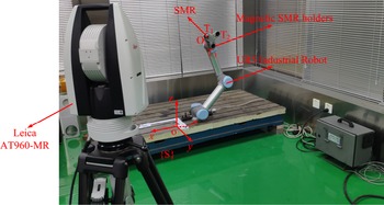
The experiments are conducted to further validate the MIM-based calibration method proposed in this paper. As shown in Fig. 11, the whole experiment system includes a Lecia AT960-MR laser tracker measurement system, a UR5 industrial robot, a terminal flange installed on the end-effector, a spherically mounted reflector (SMR), and three magnetic SMR holders mounted on the terminal flange, in which the
 $\rm Lecia AT960\rm MR$
laser tracker measurement system has a spatial measurement accuracy including the angle accuracy of
 $15\,\mu m+6\mu m/m$
and the distance accuracy of
 $0.5\,\mu m/m$
based on the specifications.
Experimental set-up of the UR5 industrial robot.

First, we establish the base coordinate frame
 $\left\{\rm S\right\}$
by driving the corresponding joint, and the frame
 $\left\{\rm S\right\}$
is coincident with the measurement coordinate frame nominally in the Spatial Analyzer Inspire software before measurement. After that, the robot is moved to the specified poses by driving each joint, the SMR is successively placed in three magnetic SMR holders, and the position coordinates of the corresponding SMR target are measured with respect to the frame
 $\left\{\rm S\right\}$
, which are denoted as
 $\rm T_1, T_2, T_3$
, respectively. Finally, three measuring points
 $\left(\rm T_1, T_2, T_3\right)$
are utilized to construct the tool coordinate frame
 $\left\{\rm T\right\}$
as the following: the origin of the frame
 $\left\{\rm T\right\}$
, which is denoted as
 $O_t$
, is located at the point
 $\rm T_1$
, the z-axis is perpendicular to the plane
 $\rm {T_1 T_2 T_3}$
, the x-axis is set along the vector
 $\rm \overline{T_1 T_3}$
, and the y-axis can be determined by the right-handed rule. Therefore, the measured poses of the frame
 $\left\{\rm T\right\}$
shown in the frame
 $\left\{\rm S\right\}$
can be obtained as follows:
 $\begin{equation*}\begin{aligned} {{{f}}}^a_{st}\left({{{q}}}\right)=\begin{bmatrix} {{{x}}} & {{{y}}} & {{{z}}} & {{{p}}}_{O_t}\\[4pt] 0 & 0 & 0 & 1\\ \end{bmatrix}\end{aligned}\end{equation*}$
where
 ${{{z}}}=\frac{\rm \overline{T_1 T_3} \times \overline{T_1 T_2}}{\Vert \rm \overline{T_1 T_3} \times \overline{T_1 T_2} \Vert}$
,
 ${{{x}}}=\frac{\rm \overline{T_1 T_3}}{\Vert \rm \overline{T_1 T_3} \Vert}$
, and
 ${{{y}}}={{{z}}} \times {{{x}}}$
As can be known from the previous analysis, 50 samples can be randomly generated within the robot workspace, of which the 30 samples are used for the calibration of kenimatic parameters, and the rest for the verification of the calibrated results.
5.2. Calibration experiment
In the calibration experiment, the UR5 industrial robot is controlled to move to randomly selected configurations. For each configuration, the measured position coordinates of three measuring points can be obtained and listed in Table III
 $\left(see \ Appendix \ B\right)$
, so as to calculate the corresponding actual poses of the frame
 $\left\{\rm T\right\}$
shown in the frame
 $\left\{\rm S\right\}$
. After that, in accordance with the kinematic parameter identification process
 $\left(\rm Fig.\,\, 4\right)$
, the final kinematic parameters are obtained via the iteration least-squares algorithm. Figure 12 depicts the pose errors of UR5 industrial robot in iteration process. It can be seen that the position and orientation errors can be significantly reduced and converge to the stable value after at least third iteration.
Pose errors of UR5 industrial robot in the iteration process.

5.3. Verification experiment
To validate whether the calibrated results could compensate for the pose errors of the robot at other configurations that are different from those in the calibration experiment, the verification experiment is performed on the UR5 industrial robot. First, the corresponding actual poses can be calculated at another 20 sets of random configurations, which are listed in Table IV
 $\left(see \ Appendix \ B\right)$
, via utilizing the position coordinates of the verification points measured with the
 $\rm Lecia AT960$
-MR laser tracker measurement system. Then, the nominal and calibration poses can be obtained according to the nominal kinematic parameters and the calibrated results. Finally, the difference between the actual poses and the other two types of poses, referred to as the pose errors before and after calibration, is illustrated in Fig. 13. After calibration, the pose accuracy of the UR5 industrial robot is significantly improved. The maximum and mean position errors are reduced from
 $9.1917 \ {\rm mm}$
and
 $4.5127 \ {\rm mm}$
to
 $1.1850 \ {\rm mm}$
and
 $0.4471 \ {\rm mm}$
, respectively. The maximum and mean orientation errors are reduced from
 $0.0161 \ {\rm rad}$
and
 $0.0117 \ {\rm rad}$
to
 $0.0017 \ {\rm rad}$
and
 $8.0474 \times 10^{-4} \ {\rm rad}$
, respectively.
Pose errors of UR5 industrial robot before and after calibration.

6. Conclusion
We propose an improved algorithm for the minimal parameter calibration based on the POE formula in this paper, the main concerns are the kinematic modeling and parameter identification. For the modeling, we define the initial pose error in the tool coordinate frame rather than the base coordinate frame and unify all twist descriptions, so as to give a unified error model through entirely mathematical derivation. Furthermore, we present a novel parameter identification method that identifies the orientation error and position error parameters separately and updates the minimal parameters uniformly, which requires no special consideration for the best weight matrix. Additionally, in each iteration, we just need to update the minimal parameters, rather than update the joint twist coordinates via the error parameters. The simulation and experiment results show that the improved calibration algorithm is feasible and effective in upgrading the absolute pose accuracy of the serial robots. Comparing with the existing identification approach of serial robots, the novel identification method exhibits much better accuracy improvement.
In addition to kinematic modeling and kinematic parameter identification, the simpler measurement and more practical compensation methods are also significant for the process of kinematic calibration. Therefore, the proposed algorithm needs to be further studied.
Acknowledgments
This work is supported by the National Natural Science Foundation of China under Grants (51605004).
Appendix
A: Adjoint Transformation
An element of a Lie group
 $SE\left( 3 \right)$
can be identified with a linear mapping between its Lie algebra via the adjoint map. The adjoint map of
 ${{{g}}} \in SE\left(3\right)$
on
 $\hat{\boldsymbol{\zeta}} \in se\left(3\right)$
is
 $\begin{equation}\begin{aligned} & Ad\left({{{g}}}\right){\hat{\boldsymbol{\zeta}}}\\[1pt] & ={{{{g}}}} \hat{\boldsymbol{\zeta}} {{{{g}}}}^{-1}\\[1pt] & =\begin{bmatrix} {{{R}}} & {{{p}}} \\ \\[-7pt] \boldsymbol{0} & 1 \end{bmatrix} \begin{bmatrix} \hat{\boldsymbol{\omega}} & {{{v}}} \\ \\[-7pt] \boldsymbol{0} & 0 \end{bmatrix} {\begin{bmatrix} {{{R}}} & {{{p}}} \\ \\[-7pt] \boldsymbol{0} & 1 \end{bmatrix}}^{-1}\\[1pt] & =\begin{bmatrix} {{{R}}}\hat{\boldsymbol{\omega}} & \hat{{{{p}}}}{{{R}}}{\boldsymbol{\omega}}+{{{R}}}{{{{v}}}} \\ \\[-7pt] \boldsymbol{0} & 0 \end{bmatrix}\end{aligned}\end{equation}$
When the joint twist
 $\hat{\boldsymbol{\zeta}}$
admits a six-dimensional vector representation denoted by
 ${\boldsymbol{\zeta}} \in \Re^{6\times1}$
, the adjoint map of
 ${{{g}}}$
on
 $\boldsymbol{\zeta}$
is
 $\begin{equation}\begin{aligned} & Ad\left({{{g}}}\right){\boldsymbol{\zeta}} \\\\[-8pt] & =\begin{bmatrix} {{{R}}} & \boldsymbol{0} \\\\[-8pt] \hat{{{{p}}}}{{{R}}} & {{{R}}} \end{bmatrix} \begin{bmatrix} \boldsymbol{\omega} \\\\[-8pt] {{{v}}} \end{bmatrix}\\ & =\begin{bmatrix} {{{R}}}{\boldsymbol{\omega}} \\\\[-8pt] \hat{{{{p}}}}{{{R}}}{\boldsymbol{\omega}}+{{{R}}}{{{{v}}}} \end{bmatrix}\end{aligned}\end{equation}$
Given
 $q\in \Re$
, the exponential of
 $\hat{\boldsymbol{\zeta}} q$
is an element of
 $SE\left( 3 \right)$
. Thus,
 $exp \left({{{g}}} {\hat{\boldsymbol{\zeta}} q} {{{g}}}^{-1}\right)$
can be given as follows
 $\begin{equation}\begin{aligned} &exp \left({{{g}}} {\hat{\boldsymbol{\zeta}} q} {{{g}}}^{-1}\right) \\[1pt] & ={{{g}}} exp \left({\hat{\boldsymbol{\zeta}} q}\right) {{{g}}}^{-1}\\[1pt] & =Ad\left({{{g}}}\right) exp \left({\hat{\boldsymbol{\zeta}} q}\right)\end{aligned}\end{equation}$
B: The Experiment Data
The position coordinates of three measuring points for the calibration

The position coordinates of three measuring points for the verification