





%20--%3e%3c!DOCTYPE%20svg%20PUBLIC%20'-//W3C//DTD%20SVG%201.0//EN'%20'http://www.w3.org/TR/2001/REC-SVG-20010904/DTD/svg10.dtd'%3e%3csvg%20version='1.0'%20id='Layer_1'%20xmlns='http://www.w3.org/2000/svg'%20xmlns:xlink='http://www.w3.org/1999/xlink'%20x='0px'%20y='0px'%20width='64px'%20height='64px'%20viewBox='5.5%20-3.5%2064%2064'%20enable-background='new%205.5%20-3.5%2064%2064'%20xml:space='preserve'%3e%3cg%3e%3ccircle%20fill='%23FFFFFF'%20fill-opacity='0'%20cx='37.785'%20cy='28.501'%20r='28.836'/%3e%3cpath%20fill='%23595959'%20d='M37.441-3.5c8.951,0,16.572,3.125,22.857,9.372c3.008,3.009,5.295,6.448,6.857,10.314%20c1.561,3.867,2.344,7.971,2.344,12.314c0,4.381-0.773,8.486-2.314,12.313c-1.543,3.828-3.82,7.21-6.828,10.143%20c-3.123,3.085-6.666,5.448-10.629,7.086c-3.961,1.638-8.057,2.457-12.285,2.457s-8.276-0.808-12.143-2.429%20c-3.866-1.618-7.333-3.961-10.4-7.027c-3.067-3.066-5.4-6.524-7-10.372S5.5,32.767,5.5,28.5c0-4.229,0.809-8.295,2.428-12.2%20c1.619-3.905,3.972-7.4,7.057-10.486C21.08-0.394,28.565-3.5,37.441-3.5z%20M37.557,2.272c-7.314,0-13.467,2.553-18.458,7.657%20c-2.515,2.553-4.448,5.419-5.8,8.6c-1.354,3.181-2.029,6.505-2.029,9.972c0,3.429,0.675,6.734,2.029,9.913%20c1.353,3.183,3.285,6.021,5.8,8.516c2.514,2.496,5.351,4.399,8.515,5.715c3.161,1.314,6.476,1.971,9.943,1.971%20c3.428,0,6.75-0.665,9.973-1.999c3.219-1.335,6.121-3.257,8.713-5.771c4.99-4.876,7.484-10.99,7.484-18.344%20c0-3.543-0.648-6.895-1.943-10.057c-1.293-3.162-3.18-5.98-5.654-8.458C50.984,4.844,44.795,2.272,37.557,2.272z%20M37.156,23.187%20l-4.287,2.229c-0.458-0.951-1.019-1.619-1.685-2c-0.667-0.38-1.286-0.571-1.858-0.571c-2.856,0-4.286,1.885-4.286,5.657%20c0,1.714,0.362,3.084,1.085,4.113c0.724,1.029,1.791,1.544,3.201,1.544c1.867,0,3.181-0.915,3.944-2.743l3.942,2%20c-0.838,1.563-2,2.791-3.486,3.686c-1.484,0.896-3.123,1.343-4.914,1.343c-2.857,0-5.163-0.875-6.915-2.629%20c-1.752-1.752-2.628-4.19-2.628-7.313c0-3.048,0.886-5.466,2.657-7.257c1.771-1.79,4.009-2.686,6.715-2.686%20C32.604,18.558,35.441,20.101,37.156,23.187z%20M55.613,23.187l-4.229,2.229c-0.457-0.951-1.02-1.619-1.686-2%20c-0.668-0.38-1.307-0.571-1.914-0.571c-2.857,0-4.287,1.885-4.287,5.657c0,1.714,0.363,3.084,1.086,4.113%20c0.723,1.029,1.789,1.544,3.201,1.544c1.865,0,3.18-0.915,3.941-2.743l4,2c-0.875,1.563-2.057,2.791-3.541,3.686%20c-1.486,0.896-3.105,1.343-4.857,1.343c-2.896,0-5.209-0.875-6.941-2.629c-1.736-1.752-2.602-4.19-2.602-7.313%20c0-3.048,0.885-5.466,2.658-7.257c1.77-1.79,4.008-2.686,6.713-2.686C51.117,18.558,53.938,20.101,55.613,23.187z'/%3e%3c/g%3e%3c/svg%3e)
%20--%3e%3c!DOCTYPE%20svg%20PUBLIC%20'-//W3C//DTD%20SVG%201.0//EN'%20'http://www.w3.org/TR/2001/REC-SVG-20010904/DTD/svg10.dtd'%3e%3csvg%20version='1.0'%20id='Layer_1'%20xmlns='http://www.w3.org/2000/svg'%20xmlns:xlink='http://www.w3.org/1999/xlink'%20x='0px'%20y='0px'%20width='64px'%20height='64px'%20viewBox='5.5%20-3.5%2064%2064'%20enable-background='new%205.5%20-3.5%2064%2064'%20xml:space='preserve'%3e%3cg%3e%3ccircle%20fill='%23FFFFFF'%20fill-opacity='0'%20cx='37.637'%20cy='28.806'%20r='28.276'/%3e%3cg%3e%3cpath%20fill='%23595959'%20d='M37.443-3.5c8.988,0,16.57,3.085,22.742,9.257C66.393,11.967,69.5,19.548,69.5,28.5c0,8.991-3.049,16.476-9.145,22.456%20C53.879,57.319,46.242,60.5,37.443,60.5c-8.649,0-16.153-3.144-22.514-9.43C8.644,44.784,5.5,37.262,5.5,28.5%20c0-8.761,3.144-16.342,9.429-22.742C21.101-0.415,28.604-3.5,37.443-3.5z%20M37.557,2.272c-7.276,0-13.428,2.553-18.457,7.657%20c-5.22,5.334-7.829,11.525-7.829,18.572c0,7.086,2.59,13.22,7.77,18.398c5.181,5.182,11.352,7.771,18.514,7.771%20c7.123,0,13.334-2.607,18.629-7.828c5.029-4.838,7.543-10.952,7.543-18.343c0-7.276-2.553-13.465-7.656-18.571%20C50.967,4.824,44.795,2.272,37.557,2.272z%20M46.129,20.557v13.085h-3.656v15.542h-9.944V33.643h-3.656V20.557%20c0-0.572,0.2-1.057,0.599-1.457c0.401-0.399,0.887-0.6,1.457-0.6h13.144c0.533,0,1.01,0.2,1.428,0.6%20C45.918,19.5,46.129,19.986,46.129,20.557z%20M33.042,12.329c0-3.008,1.485-4.514,4.458-4.514s4.457,1.504,4.457,4.514%20c0,2.971-1.486,4.457-4.457,4.457S33.042,15.3,33.042,12.329z'/%3e%3c/g%3e%3c/g%3e%3c/svg%3e)
%20--%3e%3c!DOCTYPE%20svg%20PUBLIC%20'-//W3C//DTD%20SVG%201.0//EN'%20'http://www.w3.org/TR/2001/REC-SVG-20010904/DTD/svg10.dtd'%3e%3csvg%20version='1.0'%20id='Layer_1'%20xmlns='http://www.w3.org/2000/svg'%20xmlns:xlink='http://www.w3.org/1999/xlink'%20x='0px'%20y='0px'%20width='64px'%20height='64px'%20viewBox='5.5%20-3.5%2064%2064'%20enable-background='new%205.5%20-3.5%2064%2064'%20xml:space='preserve'%3e%3cg%3e%3ccircle%20fill='%23FFFFFF'%20fill-opacity='0'%20cx='36.924'%20cy='28.403'%20r='28.895'/%3e%3cpath%20fill='%23595959'%20d='M37.442-3.5c8.99,0,16.571,3.085,22.743,9.256C66.393,11.928,69.5,19.509,69.5,28.5c0,8.992-3.048,16.476-9.145,22.458%20C53.88,57.32,46.241,60.5,37.442,60.5c-8.686,0-16.19-3.162-22.513-9.485C8.644,44.728,5.5,37.225,5.5,28.5%20c0-8.762,3.144-16.343,9.429-22.743C21.1-0.414,28.604-3.5,37.442-3.5z%20M12.7,19.872c-0.952,2.628-1.429,5.505-1.429,8.629%20c0,7.086,2.59,13.22,7.77,18.4c5.219,5.144,11.391,7.715,18.514,7.715c7.201,0,13.409-2.608,18.63-7.829%20c1.867-1.79,3.332-3.657,4.398-5.602l-12.056-5.371c-0.421,2.02-1.439,3.667-3.057,4.942c-1.622,1.276-3.535,2.011-5.744,2.2%20v4.915h-3.714v-4.915c-3.543-0.036-6.782-1.312-9.714-3.827l4.4-4.457c2.094,1.942,4.476,2.913,7.143,2.913%20c1.104,0,2.048-0.246,2.83-0.743c0.78-0.494,1.172-1.312,1.172-2.457c0-0.801-0.287-1.448-0.858-1.943l-3.085-1.315l-3.771-1.715%20l-5.086-2.229L12.7,19.872z%20M37.557,2.214c-7.276,0-13.428,2.571-18.457,7.714c-1.258,1.258-2.439,2.686-3.543,4.287L27.786,19.7%20c0.533-1.676,1.542-3.019,3.029-4.028c1.484-1.009,3.218-1.571,5.2-1.686V9.071h3.715v4.915c2.934,0.153,5.6,1.143,8,2.971%20l-4.172,4.286c-1.793-1.257-3.619-1.885-5.486-1.885c-0.991,0-1.876,0.191-2.656,0.571c-0.781,0.381-1.172,1.029-1.172,1.943%20c0,0.267,0.095,0.533,0.285,0.8l4.057,1.83l2.8,1.257l5.144,2.285l16.397,7.314c0.535-2.248,0.801-4.533,0.801-6.857%20c0-7.353-2.552-13.543-7.656-18.573C51.005,4.785,44.831,2.214,37.557,2.214z'/%3e%3c/g%3e%3c/svg%3e)
1. Introduction
A falling liquid jet into a pool of the same or another liquid is a ubiquitous phenomenon in many natural and engineering processes. When a liquid jet impinges on the surface of the same liquid stored in a cylindrical vessel, it produces different flow structures depending on the relative diameter of the vessel with respect to the jet diameter at impact denoted by the diameter ratio ( $X$) and flow rate.
If  $X \gg$ 1, the liquid contained in the vessel is commonly referred to as the pool of liquid. The studies in this category are mainly of two types: (a) continuous liquid jet impinging on a pool, typically denoted as a plunging jet; and (b) impacting droplets on the pool. Several studies explore the air entrainment mechanism in the plunging jets (Oguz Reference Oguz1998) and breaking of sea waves as summarized by Kiger & Duncan (Reference Kiger and Duncan2012). The mechanisms proposed for entrainment modelling involve the relative interplay of inertial forces, viscous forces and surface tension forces. When a plunging jet strikes the pool of water, a crown-like splash of a thin water sheet is generated that cannot sustain itself and disintegrates quickly, as studied by Zhu, Oğuz & Prosperetti (Reference Zhu, Oğuz and Prosperetti2000). They also modelled the air cavity surrounding the jet core near the impact point. On the other hand, when a liquid drop impinges on a pool of the same liquid (Prosperetti & Oguz Reference Prosperetti and Oguz1993; Rein Reference Rein1993), it also forms a crater surrounded by a crown-like transient ejecta sheet (Worthington Reference Worthington1908; Engel Reference Engel1966; Thoroddsen Reference Thoroddsen2002).
To the best of the authors’ knowledge, no studies are present in the literature for  $X \approx 1$, which is the focus of the current investigation. The investigation is inspired by the serendipitous observation made during washing of a vial in a kitchen sink. The water, while gushing out of the vial, transforms into a liquid sheet of different shapes, namely open upward (inverted umbrella-like), horizontal and downward bell (umbrella-like and closed). A literature survey showed that these structures have been studied in the past and are generally referred to as water bells.
A summary of the literature when a laminar jet impinges on a solid deflector disc for  $X_s \approx 1$, where
 $X_s$ is the ratio of jet diameter at impact and deflector disc's diameter, is presented below. The closed downward water sheet structure, produced by a downward jet striking a flat disc, is denoted as a water bell in the literature. The water bell entraps air as it encloses on the rod that supports the flat disc. The study on the water bells was first started by Savart (Reference Savart1833a,Reference Savartb,Reference Savartc,Reference Savartd). He studied the formation of water bells using different jet and impactor diameters and reported the shape of the bell. Boussinesq (Reference Boussinesq1869a,Reference Boussinesqb) derived the governing equation of the water sheet to predict the water bell shape obtained by Savart (Reference Savart1833a). Later on, the radius of the horizontal sheet was used as a means to calculate the surface tension of water by Bond (Reference Bond1935) and Buchwald & König (Reference Buchwald and König1936). Unlike Boussinesq (Reference Boussinesq1869a,Reference Boussinesqb) who used no pressure difference between the inside and outside of the bell, Lance & Perry (Reference Lance and Perry1953) rederived the equation and obtained a numerical solution with a difference in inside and outside pressure. A series of papers were published by Sir G. I. Taylor where he used a horizontal jet impinging on a solid deflector to produce water bells; he obtained an analytical solution of the theoretical equation governing the bell shape when the effect of gravity is negligible (Taylor Reference Taylor1959a). Furthermore, he studied the formation of instability waves on the surface of the water bells (Taylor Reference Taylor1959b) and their role in the breakup of the fluid sheets (Taylor Reference Taylor1959c). Clanet (Reference Clanet2000, Reference Clanet2001) revisited the problem with an experimental set-up similar to Savart (Reference Savart1833a) and studied the bell shape prediction and the stability of the bells. An expression for the ejection angle of the liquid sheet detaching at the edge of the impactor disc for closed downward bells was also obtained by Clanet (Reference Clanet2001). Jameson et al. (Reference Jameson, Jenkins, Button and Sader2008, Reference Jameson, Jenkins, Button and Sader2010) and Button et al. (Reference Button, Davidson, Jameson and Sader2010) used a liquid jet directed vertically upward onto a large flat deflector plate and observed the formation of water bells.
An adjustable lip adjoining a deflector disc was used to generate horizontal water sheets of a smooth (Marmottant, Villermaux & Clanet Reference Marmottant, Villermaux and Clanet2000; Clanet & Villermaux Reference Clanet and Villermaux2002; Villermaux & Almarcha Reference Villermaux and Almarcha2016), flapping (Villermaux & Clanet Reference Villermaux and Clanet2002) and undulating (Bremond, Clanet & Villermaux Reference Bremond, Clanet and Villermaux2007) nature for the atomization and fragmentation studies. Similar experimental set-ups were also used to generate and study crumpled water bells (Aristoff et al. Reference Aristoff, Lieberman, Chan and Bush2006; Lhuissier & Villermaux Reference Lhuissier and Villermaux2012). Open inverted bells were produced by the head-on collision of two jets (Savart Reference Savart1833b; Paramati & Tirumkudulu Reference Paramati and Tirumkudulu2016). The formation of polygonal water bells was reported by Buckingham & Bush (Reference Buckingham and Bush2001). Bark et al. (Reference Bark, Wallin, Gällstedt and Kristiansson1979) imposed a swirling velocity on the ejecting liquid sheet through an annulus slit to study the swirling water bells experimentally and theoretically. Speirs et al. (Reference Speirs, Mansoor, Belden, Hurd, Pan and Truscott2018) observed the formation of a water sheet structure resembling the shape of a champagne glass when they suddenly released water held in a tube.
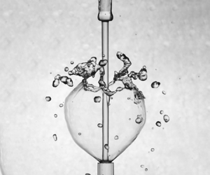
As described above, one needed different experimental arrangements to produce upward, horizontal and downward water bells. Primarily, an adjustable lip adjoining the flat deflector disc, solid deflector discs of different shapes and head-on colliding jets were used. However, in the current study, all possible water bell shapes have been obtained in a single experimental arrangement by impinging a liquid jet on the surface of the same liquid in a vial of similar diameter (figure 1), thus providing a general framework for studying water bells; both experimentally and theoretically. This approach paves the way for developing a unified modelling using the experimental data that demarcates different regimes, and identifying the important non-dimensional parameters.
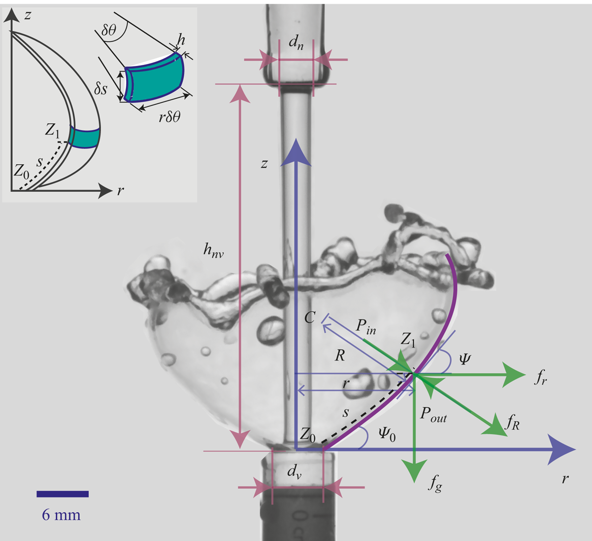
Schematic showing the coordinate system, geometric parameter and the forces acting on a fluid element. The inset illustrates an enlarged view of an infinitesimal CV attached to the fluid element at point  $Z_1$.
In our previous paper (Mohd, Yadav & Das Reference Mohd, Yadav and Das2022) we introduced the same experimental set-up and obtained steady upward, horizontal and downward water bells. Several other periodic phenomena with different flow structures are observed in the present study. We provide a regime diagram, hitherto unknown, for predicting all the observed steady and unsteady water bells. The regime diagram classifies these water bells into four distinct regimes. A control volume (CV) analysis is also carried out to obtain a semi-empirical expression for theoretically predicting the ejection angles that determine the regimes of water bells. We also model the periodic water bells to determine the rise time and trajectory.
In the case of periodic unsteady structures, we describe the atomization of the free edge leading to upward moving high-speed droplets, which is generated by sheet tearing. However, the fragmentation dynamics of the water bell sheet has not been addressed in the current work. Interested readers are referred to the recent work of Wang & Bourouiba (Reference Wang and Bourouiba2017), Wang et al. (Reference Wang, Dandekar, Bustos, Poulain and Bourouiba2018) and Wang & Bourouiba (Reference Wang and Bourouiba2018, Reference Wang and Bourouiba2021, Reference Wang and Bourouiba2022, Reference Wang and Bourouiba2023). In these papers, authors investigated a flat, radially expanding sheet when a drop impacts on a solid surface of comparable size. The readers are also encouraged to consult the review by Villermaux (Reference Villermaux2007).
In § 2 we present a theoretical framework to analyse the current problem, along with the dimensional analysis for the identification of the governing non-dimensional parameters. The details of the experimental set-up and methodology are discussed in § 3, followed by the qualitative description of different types of water bells observed in § 4. Section 5 describes regime diagrams in the two-dimensional parametric space of governing non-dimensional numbers. The modelling of the ejection angle in § 6 and the trajectory and rise time of puffing water bells in § 7 provide a theoretical explanation for the observations. We present conclusions based on the experiments and theoretical analysis in § 8.
2. Governing equations and important parameters
Consider the schematic given in figure 1, where a steady laminar jet is emanating from a nozzle with an internal diameter  $d_n$ and impinging on the surface of a liquid in a vial of internal diameter
 $d_v$, coaxially mounted at a vertical distance of
 $h_{nv}$ from the nozzle exit. As the incoming jet impinges on the surface of the liquid in the vial, a liquid sheet starts ejecting from the periphery of the vial mouth. Depending on the mass flow rate
 $\dot {m}$,
 $d_n$,
 $d_v$ and
 $h_{nv}$, the ejected water forms different water sheet structures, e.g. inverted water bell as shown in figure 1. This schematic shows a front view taken from a camera mounted with an optical axis perpendicular to the axis of the falling jet. Hence, all the dimensions and forces are shown in the plane passing through the cylindrical axis, considering the problem to be axisymmetric.
For the theoretical treatment of the present problem, a cylindrical coordinate system with the origin at the centre of the vial mouth with the cylindrical axis ( $z$) aligned along the axis of the falling jet is chosen. The ejection of the sheet starts at point
 $Z_0$ with an ejection angle
 $\psi _0$ and velocity
 $v_0$ and forms a water bell, moving under the influence of inertial, surface tension, gravity and pressure forces. The state of the forces is shown at a point
 $Z_1$ at an
 $s$ arc length away from the
 $Z_0$, where the surface tangent makes an angle
 $\psi$ from the horizontal in the anticlockwise direction. An infinitesimal CV, at point
 $Z_1$, fixed to a fluid element moving along the streamline on the water bell is shown in the inset of figure 1. The CV subtends an angle
 $\delta \theta$ in the horizontal plane to the
 $z$ axis and has a mass
 $\delta m = \rho \delta s r\delta \theta h$. The radius of curvature in the vertical (
 $r$–
 $z$) plane with an instantaneous centre
 $C$ is
 $R$, whereas
 $r$ denotes the curvature radius in the horizontal plane (with a normal in the
 $z$ direction) passing through the point
 $Z_1$. The curvature in the vertical and horizontal planes gives rise to the Laplace pressures
 $2\sigma /R$ and
 $2\sigma /r$ (
 $\sigma$ being the surface tension), respectively, as determined from the Young–Laplace equation (Boussinesq Reference Boussinesq1869a; Lance & Perry Reference Lance and Perry1953; Rowlinson & Widom Reference Rowlinson and Widom1982) and the corresponding forces acting on the fluid element at point
 $Z_1$ are given as
 $f_R=(2\sigma /R)\delta s r \,{\rm d}\theta$ and
 $f_r=(2\sigma /r)\delta s r\,{\rm d}\theta$, respectively. Here
 $P_{in}$ and
 $P_{out}$ are the pressures inside and outside of the water bell surface;
 $f_g$ denotes the force due to gravity.
The differential equation of the water sheet trajectory was first derived by Boussinesq (Reference Boussinesq1869a) and later revisited by Lance & Perry (Reference Lance and Perry1953). Taylor (Reference Taylor1959a) and Clanet (Reference Clanet2000) used different non-dimensional forms of the same governing equations. Here, we summarize the equations (for a detailed derivation, the reader is referred to Mohd et al. (Reference Mohd, Yadav and Das2022)), in the dimensional form, for the purpose of completeness following Lance & Perry (Reference Lance and Perry1953). The thickness of the water sheet,  $h$, at a general point
 $Z_1$ (figure 1) can be given as
 $\dot {m}/ (2{\rm \pi} r\rho u)$ using the continuity principle, where
 $u$ denotes the magnitude of the fluid velocity at point
 $Z_1$. Application of the conservation of the linear momentum in the tangential direction yields the relation
 $u^2= v_0 ^2 -2gz$,
 $g$ being the acceleration due to gravity. The balance of the linear momentum in the normal direction gives the relation
 \begin{equation} \frac{2\sigma}{R} + \frac{2\sigma}{r} \sin\psi + (P_{in} - P_{out}) + \rho h g \cos\psi = \frac{\rho u^2 h}{R}, \end{equation}
which can be further simplified into (2.2) using the definition of the radius of curvature given as  $1/R = {\rm d}\psi /{\rm d} s = z''/\{(1+z'^2)^{(3/2)} \}$,
 $z'$ and
 $z''$ being the first and second derivative with respect to
 $r$. The governing equation for the water bell trajectory is obtained as
 \begin{equation} z''=\frac{1 +z'^2}{e-\beta r} \left(\frac{\gamma}{e} + \beta z' + \alpha r (1+z'^2)^1/2\right), \end{equation}
where  $e=\sqrt {1+2\gamma z}$,
 $\gamma =g/v_0^2$,
 $\alpha =2{\rm \pi} (P_{in} - P_{out})/\dot {m}v_0$ and
 $\beta = 4{\rm \pi} \sigma /\dot {m}v_0$.
Equation (2.2) (same as obtained by Lance & Perry Reference Lance and Perry1953) would be used to compare the profiles of bells obtained from the experiments as given in figure 17 of §,7.1. The solution of the above mentioned (2.2) requires the known initial conditions, i.e.  $\psi _0$ as
 ${\rm d} z/{\rm d} r|_{Z_0} = \tan (\psi _0)$ and
 $v_0$ at point
 $Z_0$ (
 $r = d_v/2, z = 0$), which need to be obtained from the experimental measurement or from analytical expressions if they could be derived. The numerical solution has been obtained using MATLAB
 's ode45 solver, an adaptive step size algorithm, with the initial conditions at point
 $Z_0$ as
 $z =0$ and
 ${\rm d} z/{\rm d} r = \tan (\psi _0)$. The ode45 solver employs an explicit Runge–Kutta (4,5) method (Dormand & Prince Reference Dormand and Prince1980; Shampine & Reichelt Reference Shampine and Reichelt1997) that calculates the error for the fourth-order solution combining the fourth- and fifth-order accurate Runge–Kutta solution. To calculate the coefficients
 $\alpha$,
 $\beta$ and
 $\gamma$ in (2.2), the value of velocity
 $v$ (defined in the next paragraphs) is used as
 $v_0$.
The experimental control parameters  $d_n$,
 $v_n = 4 \dot {m}/({\rm \pi} \rho d_n ^2)$ and
 $h_{nv}$ are transformed in the form of the velocity scale,
 $v$, and length scale,
 $d$, at the vial mouth using the Bernoulli equation between the nozzle exit and vial mouth. Note that this is an idealized scenario where the jet is allowed to fall upto the vial mouth assuming the absence of the vial, thus neglecting the effects of meniscus formation at the vial mouth. Applying the Bernoulli equation between the nozzle exit and a point at
 $z$ distance downstream:
 \begin{equation} \frac{1}{2}\rho v_n ^2 - \frac{1}{2} \rho v(z) ^2 ={-}\rho g z + 2\sigma \left(\frac{1}{d(z)}-\frac{1}{d_n}\right). \end{equation}
The pressure,  $p(z)$, inside the incoming jet is calculated using the Young–Laplace equation as
 $p(z) - p_a =\sigma /r(z) + \sigma /r_{\infty }$, where
 $r(z)$ and
 $r_{\infty } = \infty$ are the radius of curvature in the planes with the normals parallel and perpendicular to the
 $z$ axis, respectively (Rapp Reference Rapp2022). The atmospheric pressure is denoted by
 $p_a$. Equation (2.3) can be manipulated further to obtain
 $v(z)$ as
 \begin{equation} \left(\frac{v(z)}{v_n}\right)^2 = 1 + \frac{2}{{Fr}_{n}^2} \frac{z}{d_n} + \frac{4}{{We}_{n}}\left( 1 - \frac{d_n}{d(z)}\right), \end{equation}
where  ${Fr}_n$ and
 ${We}_n$ are the Froude number and Weber number at the nozzle exit. Using the continuity equation between the nozzle exit and the point at
 $z$ gives
 \begin{equation} D^2 V=1, \end{equation}
where  $D=d(z)/d_n$ and
 $V =v(z)/v_n$ are the normalized diameter and velocity with respect to nozzle exit conditions. Moreover, the argument
 $z$ in the normalized parameters has been dropped for clarity. Using (2.5), (2.4) can be solved for
 $D$ and
 $V$ as
 \begin{equation} \left. \begin{gathered} \displaystyle \left(1 + \frac{2 Z}{{Fr}_{n}^2} + \frac{4}{{We}_{n}}\right) D^4 - \left(\frac{4}{{We}_{n}}\right) D^3 -1=0; \\ \displaystyle V = \frac{1}{D^2}, \end{gathered}\right\} \end{equation}
where  $Z=z/d_n$ is the non-dimensionalized downstream distance. Taking
 $z=h_{nv}$, the velocity
 $v\ (z=h_{nv}) = v$ and diameter
 $d\ (z=h_{nv}) = d$ at the vial mouth can be calculated.
To probe the functional dependency of various parameters on ejection angle ( $\psi _0$), dimensional analysis has been carried out using Buckingham
 ${\rm \pi}$ theorem. As shown in figure 1,
 $\psi _0$ is assumed to depend on fluid properties such as surface tension (
 $\sigma$), density (
 $\rho$) and viscosity (
 $\mu$), geometric properties such as jet diameter at impact (
 $d$) and vial diameter (
 $d_v$), and the flow property, i.e. jet velocity (
 $v$) at the vial mouth. The functional form can be written as
 $f(\psi _0,d_v,d,v,\rho, \mu, \sigma, g) = 0$. The functional relationship has three fundamental dimensions – mass, length and time – therefore, it has five non-dimensional parameters (
 ${\rm \pi}$ groups). Taking
 $d$,
 $v$ and
 $\sigma$ as repeating variables, the
 $i$th
 ${\rm \pi}$ group can be given as
 ${\rm \pi} _i=d ^a v^b \sigma ^c (V_i)$, where
 $V_i$ represents one of the remaining variables. Exponents
 $a, b, c$ are to be determined for each
 ${\rm \pi}$ group using the Buckingham
 ${\rm \pi}$ theorem (Bridgman Reference Bridgman1931; Gibbings Reference Gibbings2011). The resulting dimensionless groups are
 \begin{equation} {\rm \pi}_{i} =
\left\{\begin{array}{@{}ll@{}} \psi_0 \quad\mbox{(ejection
angle)}, \\ \displaystyle X
= \dfrac{d_v}{d} \quad\mbox{(diameter ratio)}, \\
\displaystyle We = \dfrac{\rho
v^2 d}{\sigma} \quad\mbox{(Weber number)}, \\
\displaystyle Ca=
\dfrac{\mu v}{\sigma} \quad\mbox{(capillary
number)}, \\ \displaystyle
Fr= \dfrac{v}{\sqrt{g d}} \quad\mbox{(Froude
number)}. \end{array}\right.
\end{equation}
The obtained  ${\rm \pi}$ groups are independent and provide a basis for the non-dimensional parameters that govern the physical problem. However, the independent
 ${\rm \pi}$ groups obtained using the Buckingham
 ${\rm \pi}$ theorem are not unique and depend upon the selection of repeating parameters during the analysis. The functional relationship in the form of non-dimensional parameters can be written as
 \begin{equation} \psi_0 = f(X, We, Ca, Fr), \end{equation}
whereas the function  $f$ is unknown. This functional relationship would be used to classify different water bell regimes observed in the current investigation in § 5.
3. Experiments
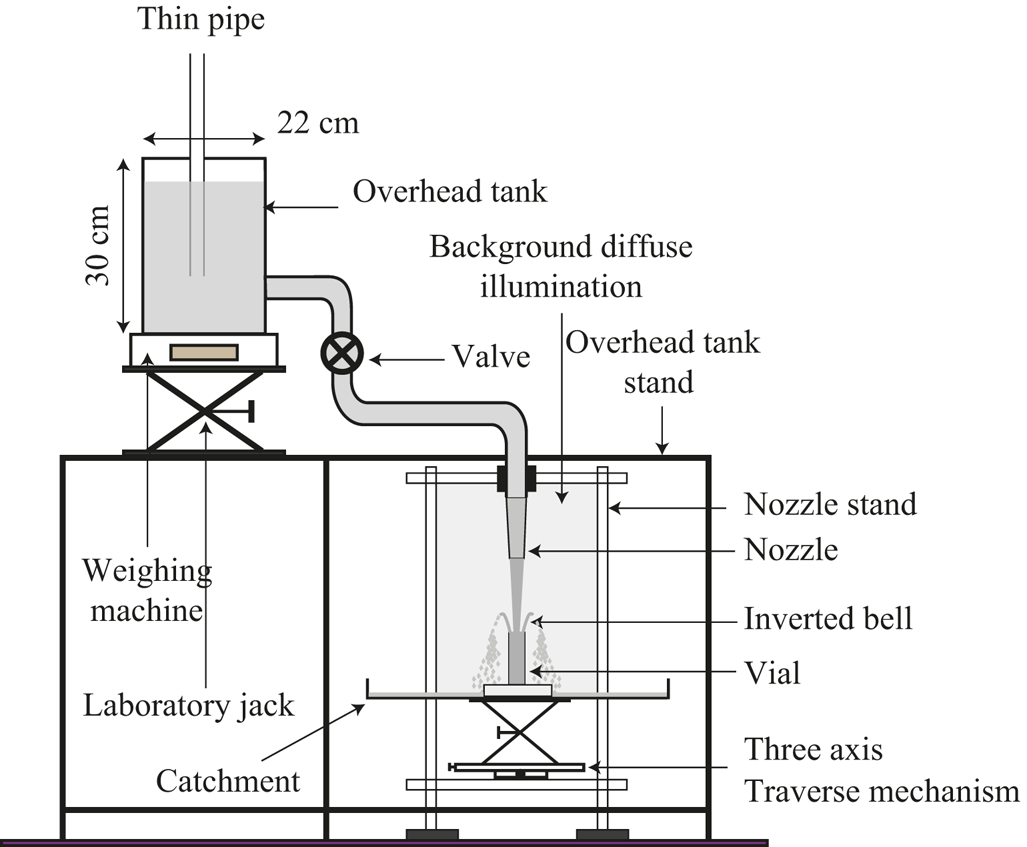
A schematic of the experimental set-up used in the current study is shown in figure 2. The water is supplied from a reservoir, based on the Mariotte bottle principle (Biswas et al. Reference Biswas, Sharma, Saha and Das2022), placed on top of a precision weighing balance (Citizon CG 6102) with an accuracy of 0.01 g. The receiving vial of cylindrical shape was mounted on a three-axis traverse to control the alignment and the separation distance from the nozzle. A flexible PVC pipe fitted with a ball valve connects the overhead tank to the nozzle. The flow rate was controlled using the valve and by varying the elevation of the overhead tank with the help of a laboratory jack that supported the weighing balance. For the mass flow calculations, images of the weighing balance readings were acquired at 10 frames per second (fps) over a period of 60 s using an IMPERX
 B2320M camera having a resolution of
 $2352 \times 1768$ px. Next, the weighing scale readings were plotted with time and a straight line is fitted to this data to get the mass flow rate. The field of view was illuminated using diffused, flicker-free lighting; produced when a background screen, a plastic sheet covered with white paper, was illuminated using a 1000 W halogen lamp from behind. The images were acquired using the front (IDT
 OS10-4 K:
 $3840 \times 2400$ px) and top (NanoSense MK III-IDT
 :
 $1280 \times 1024$ px) high-speed cameras. The surface tension of the water was calculated using a contact angle goniometer. The free-falling, low-speed jet from the nozzle was used as a reference for vertical alignment of the front camera. Furthermore, the alignment of the vial axis with the axis of the nozzle was achieved using the grid lines on the front camera frame aided by STANLEY
 CL90, the twin-beam self-levelling cross-line laser. The supply reservoir and connecting pipes were supported by a rigid steel frame, whereas the nozzle and vial in the measurement section are mounted on a heavy aluminium fixture. The separation arrangement shields the delicate nozzle–vial alignment from vibratory disturbances due to repeated filling of the supply reservoir.
Schematic of the experimental set-up.
The small velocity fluctuations in the incoming flow were dampened using a nylon screen with a pore size of approximately  $1\,\mathrm {\mu }$m at the entrance of the nozzle. The laminarity of the jet was verified by comparing the experimentally measured diameter of the jet slightly above the vial mouth (to avoid the meniscus), with the laminar inviscid theory given by (2.6) (González-Mendizabal, Olivera-Fuentes & Guzmán Reference González-Mendizabal, Olivera-Fuentes and Guzmán1987; Hancock & Bush Reference Hancock and Bush2002; Rapp Reference Rapp2016). The glass nozzle uses a cylindrical inlet section with an internal diameter of 9.72 mm, followed by a tapered outlet section with exit internal diameters (
 $d_n$) of 8, 6 and 4 mm. For each
 $d_n$ mentioned, the lengths of the cylindrical sections are 40, 37 and 37 mm, respectively, whereas the lengths of the tapered sections are 28, 58 and 77 mm, respectively. The depth of the vials is taken as 10 times the internal diameter,
 $d_v$. This depth is sufficiently large such that increasing it further does not affect the ejection sheet dynamics, as described in Appendix C.
The experimental metric chosen for the current study is given in table 1. It can be seen from the table that each combination of nozzle diameter ( $d_n$), vial diameter (
 $d_v$) and height (
 $h$), as defined in figure 1, are denoted by the run number (from
 $r_1 \textrm { to } r_{19}$) in the first column. The numerical value of the height referred to by column
 $h$ is given in column
 $h_{nv}$. Also, for each run, the
 $\dot {m}$ is varied from low to high. The case identification in the form
 $r_{*}\dot {m}_{*}$ is used throughout the paper for referring to a particular experimental case. The
 $*$ symbol denotes the
 $*$th value of the parameter preceding it. For example, case identification
 $r_1\dot {m}_3$ represents the case for run 1 where
 $d_n = 8$,
 $d_v=8$ and
 $h=1$, which corresponds to
 $h_{nv} = 129.5$ and
 $\dot {m}_3 = 25.01$ with the respective units as specified in table 1.
Experimental parameters – nozzle diameter ( $d_n$), vial diameter (
 $d_v$), height difference count (
 $h$), value of height difference between nozzle and vial (
 $h_{nv}$) and mass flow rate (
 $\dot {m}$) for the present study.

To understand the physical process behind the formation of water bells, the qualitative nature of the flow field inside the vial mouth is obtained using particle visualization. It is to be noted here that the particle visualizations obtained are affected by the distortion introduced by the glass vial curvature and the refractive index mismatch due to glass, water and air interfaces. Therefore, these results are not used for quantitative conclusions but rather as a tool for the qualitative flow visualization. More details about the particle visualization analysis are presented in Appendix B. The result of the qualitative flow visualization inside the vial mouth are discussed in Appendix C.
4. Experimental results: flow features
This section presents descriptions of the observed water sheet structures. The experiments were performed for each combination of a particular vial diameter ( $d_v$), nozzle diameter (
 $d_n$) and height difference between nozzle and vial (
 $h_{nv})$; and then changing the mass flow rate (
 $\dot {m}$) from minimum to maximum. This procedure was repeated for all the nozzle and vial combinations presented in table 1. For each
 $\dot {m}$, before acquiring the images, sufficient time was allowed for the flow to stabilize and to subside the unsteady behaviour due to valve operation. The water bells observed are grouped into four regimes based on their distinct flow features.
4.1. Regime I: pre-sheet
At low flow rates, it was observed that the water, while gushing out of the vial, does not eject as a sheet. A blob of fluid is formed at the vial mouth as shown in figure 3. In some cases, we can also observe intermittent sheet formation but it cannot sustain itself and collapses back into the blob. The experimental metric used for pre-sheet experiments is given in table 6 of Appendix A. A plausible explanation for the pre-sheet regime at low flow rates, is that the inertial forces are not strong enough to overcome gravity and viscosity, thus the surface tension folds the fluid into a blob.
Flow structure during regime I: pre-sheet; representative images for case  $r_1\dot {m}_1$ as given in table 1, showing synchronized images for the (a) front view and (b) tilted top view (see the supplementary video, figure 3 available at https://doi.org/10.1017/jfm.2024.928).

4.2. Regime II: puffing
As we increase the flow rate, regime II, puffing is observed. Puffing is characterized primarily by the periodic formation and collapse of upward water bells. In each puffing cycle the water sheet rises upwards and then collapses due to collision with the incoming jet or increased bell rim weight. Subsequently, a new bell sheet starts to form, thus completing the puffing cycle. As the observations in this regime are interesting and novel, an extensive number of experiments are carried out. With increasing mass flow rate, three sub-regimes of the puffing are observed: (i) puffing bell-jet collision, (ii) self-collapsing puffing bell and (iii) violent collapse and formation.
4.2.1. Puffing bell-jet collision
A typical puffing cycle, in this sub-regime, is shown in figure 4. On increasing the flow rate, the relative magnitude of the inertial forces acting on the fluid ejecting from the vial increases compared with the surface tension, which tries to fold the sheet towards the jet axis, and the gravity force that tries to pull the sheet downwards. After a certain threshold of the inertial forces, the ejection of the sheet starts (figure 4a). The sheet grows gradually as its diameter increases. The mass accumulation at the sheet edge results in the formation of a rim, which can be seen as it moves upwards against gravity. The rim forms ligaments that fragment into droplets, which fall outside the bell and do not affect the sheet (figure 4b). After the diameter of the upward-rising bell sheet reaches the maxima, the sheet starts to retract inward due to surface tension and the radius of the rising water bell decreases. As the surface tension forces become dominant over the inertial forces, the sheet retracts inwards to minimize the surface energy. The retracting bell front engulfs the incoming jet as shown in figure 4(c). The trajectory of the rising puffing bell is governed by (2.2). A comparison of the experimental and theoretical puffing bell trajectories is provided in § 7.1 and figure 17. As the sheet front hits the jet, the incoming jet starts to destabilize. This leads to the formation of necking in the bell near the vial mouth (figure 4d). Finally, the upward water bell collapses along with the incoming jet (a detailed description of the collapse is given further in this section) as in figure 4(e). The jet recovers into its undisturbed laminar state as in figure 4(a) and a new puffing cycle begins (figure 4f).
Different stages of flow evolution in a puffing cycle for a puffing bell-jet collision case  $r_{17}\dot {m}_3$ at times (ms): (a) 10 (0.03), (b) 87 (0.31), (c) 172 (0.61), (d) 190 (0.68), (e) 204 (0.73), ( f) 280(1), where the time in the parentheses is normalized to the puffing cycle period. The left and right images in each panel show the synchronized front and tilted top views, respectively (see the supplementary video, figure 4).

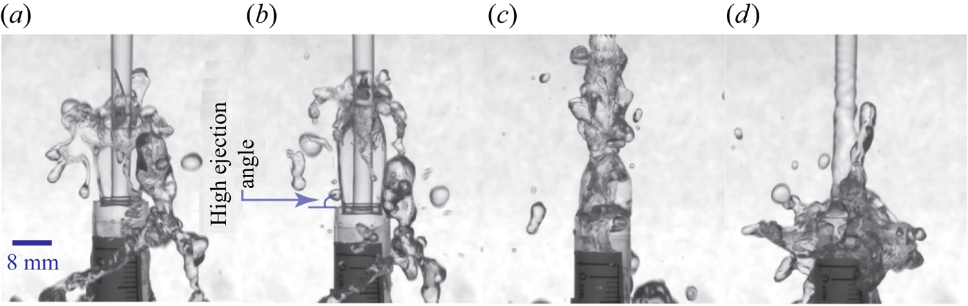
In comparison to the typical puffing cycle as described above (figure 4), for relatively low flow rates, the ejecting sheet is almost vertical ( $\psi _0 \approx 90^{\circ }$) and forms high-frequency puffing water bells as shown in figure 5. The time sequence in figure 5 demonstrates (a) the rising upward water bell, (b) an upward water bell just before collapse, (c) the post-collapse state and (d) the re-strengthening of the jet for the subsequent puffing cycle.
Puffing at a nearly vertical ejection angle for the case  $r_6\dot {m}_1$, the images are captured at times (ms): (a) 29 (0.17), (b) 36 (0.21), (c) 68 (0.39) and (d) 156 (0.90), where the time in the parentheses is normalized to the puffing cycle period.
4.2.2. Details of the bell collapse for the sub-regime: puffing bell-jet collision
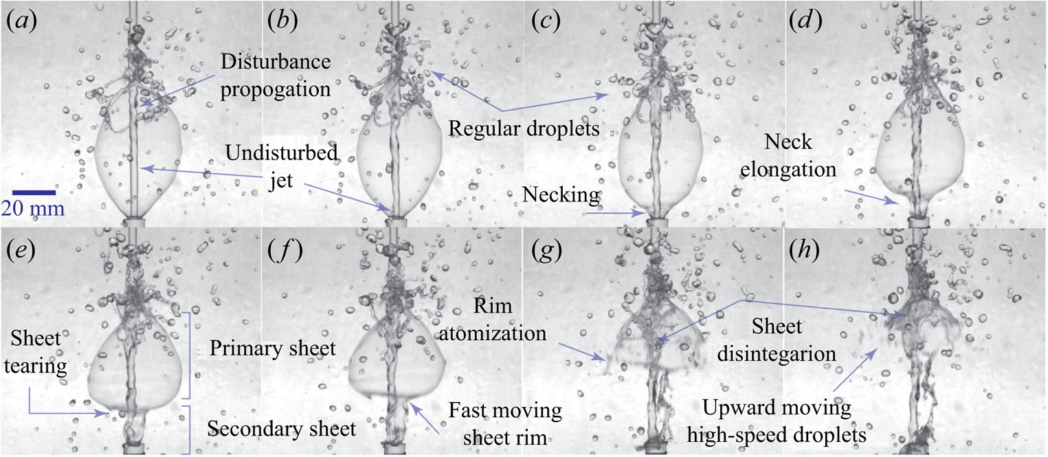
The analysis of the puffing water bell's disintegration revealed a mechanism for the formation of high-speed droplets besides the regular droplets from the rim atomization. As the sheet hits the incoming jet, a disturbance is created near the collision point (figure 6a,b). At the collision point, the upward momentum of the sheet fluid opposes the downward momentum of the incoming jet and the jet starts to decelerate, leading to the mass accumulation (figure 6c,d). The propagation of the disturbance due to mass flow rate reduction from the collision point towards the vial mouth can be seen in figures 6(a) and 6(b) along with the undisturbed jet segment after it, in the downstream direction. When the disturbance reaches the mouth of the vial, it changes the initial conditions,  $v_0$ and
 $\psi _0$, that determine the trajectory of the sheet (§ 7). This leads to the ejection of almost a vertical sheet (referred to as secondary sheet in this paragraph) from the vial mouth similar to the low flow rate puffing bells as described in figure 5. The discontinuity in the bell sheet at the junction of the primary and secondary sheet leads to the formation of necking (figure 6c). The fluid in the primary sheet is moving with higher speed as compared with the secondary sheet because of reduction in mass flow rate at the vial mouth. The fluid from the primary sheet is continuously being plunged onto the incoming jet, however, the deficit is not being supplemented by the slow moving secondary sheet, leading to the thinning of the primary bell sheet. The slow moving secondary sheet forms an elongated neck (figure 6d). Subsequently, the primary sheet gets so thin that it tears near the discontinuity (figure 6e) and the newly formed rim moves rapidly upwards (figure 6f,g). As the sheet tears, an imbalance in the surface tension forces in the vertical plane is created, which provides the required momentum for the high-speed rim and droplet motion. The fast moving rim further thickens and finally gets atomized into the droplets (figure 6g). These droplets keep on moving upward with a relatively very high speed (figure 6h). The upper segment of the primary bell sheet also disintegrates but does not produce high-speed droplets, rather the fluid ligaments get plunged onto the incoming jet (figure 6g,h).
Image sequence depicting puffing water bell disintegration, producing upward moving high-speed droplets besides the regular falling droplets from rim fragmentation for the case  $r_{16}\dot {m}_2$. The images are captured at times (ms): (a) 122 (0.43), (b) 133 (0.47), (c) 138 (0.49), (d) 144 (0.51), (e) 148 (0.53), ( f) 152 (0.54), (g) 159 (0.57) and (h) 163 (0.58), where the time in the parentheses is normalized to the puffing cycle period (see the supplementary video, figure 6).
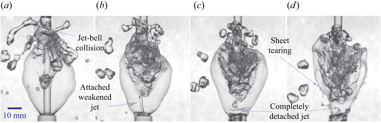
At some parametric ranges a bell is observed to exist even after the incoming jet totally gets detached from the vial mouth (figure 7c,d). In these cases the mass accumulation is so prominent (figure 7a) that it totally cuts off the supply of liquid to the vial mouth. Figure 7(b) shows the incoming jet weakening, prior to the total cutoff (figure 7c). The water bell sheet tears (figure 7d) immediately after the total cutoff as a result of sever thinning of the bell sheet.
A peculiar case of the puffing water bell showing weakening and subsequent complete detachment of the incoming jet from the vial enclosed by the closed upward water bell for the case  $r_1\dot {m}_3$ at times (ms): (a) 137 (0.46), (b) 162 (0.54), (c) 177 (0.59) and (d) 187 (0.63), where the time in the parentheses is normalized to the puffing cycle period (see the supplementary video, figure 7).
4.2.3. Self-collapsing puffing bell
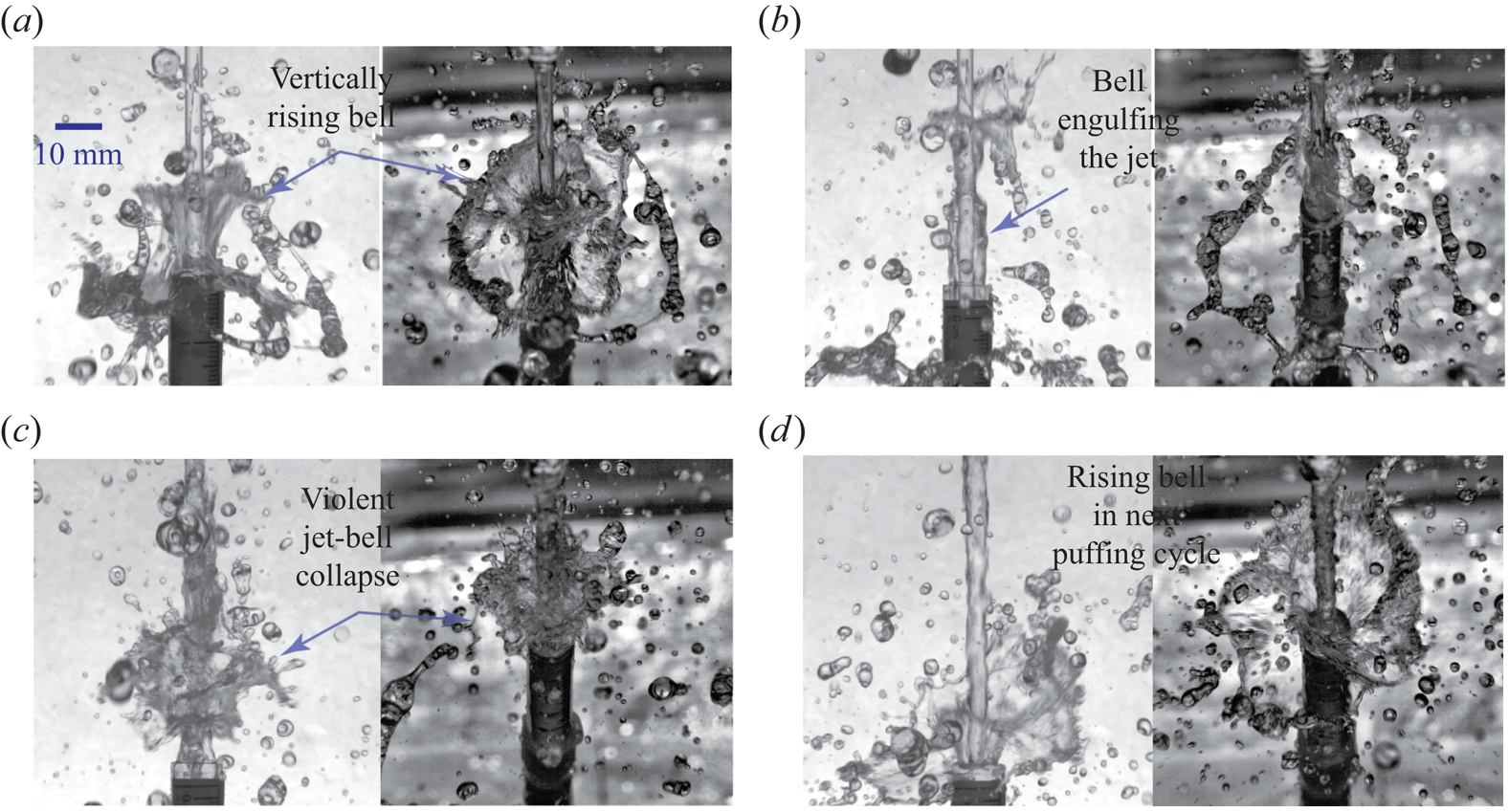
At slightly higher flow rates than those observed in puffing bell-jet collapse sub-regimes, the mechanism governing the collapse of water bells shifts from collapsing onto the jet to self-weight collapse. At these particular parameter ranges, the maximum bell diameter is relatively large. When the sheet starts to contract back towards the jet, the rim thickness increases considerably to satisfy the conservation of mass. This increases the magnitude of the gravity forces as compared with the inertial and surface tension forces and sheet gets destabilized. Figure 8(a) shows an upward-rising bell that has reached its maximum diameter and starts to curve inwards. Figure 8(b) shows the rim thickens as the water bell folds inwards. The thickened and heavy water bell rim falls and penetrates the inner part of the bell leading to total collapse (figure 8c). However, the incoming jet remains undisturbed, unlike the jet collapse case and a new inverted water bell starts to rise again as a part of the next puffing cycle (figure 8d).
Self-collapsing puffing bell for case  $r_1\dot {m}_5$, at times (ms): (a) 133 (0.43), (b) 193 (0.62), (c) 294 (0.95) and (d) 367 (1.18), where the time in the parentheses is normalized to the puffing cycle period. The left and right images in each panel show the synchronized front and tilted top views, respectively (see the supplementary video, figure 8).

4.2.4. Puffing bells: violent collapse and formation
Certain combinations of vial diameter, nozzle diameter and flow rate eject a periodic highly transient fluid sheet that gets fragmented into fast moving droplets. The puffing cycle starts when a sheet front rises upward, approximately vertically, wrapping the incoming jet as shown by a representative case in figure 9(a). The highly turbulent rising bell front curves inwards and then collapses on the jet leading to the destabilization of the incoming jet. A typical sheet structure just before the sheet front collapses on the incoming jet is shown in figure 9(b). Finally, the jet collapses violently along with the transient upward bell, marking the end of the puffing cycle (figure 9c). After the collapse, the jet re-strengthens and forms the next violent puffing cycle (figure 9d).
Puffing bells: violent collapse and formation for the case  $r_{14}\dot {m}_1$ at times (ms): (a) 11 (0.09), (b) 28 (0.24), (c) 53 (0.46) and (d) 126 (1.09), where the time in the parentheses is normalized to the puffing cycle period. The left and right images in each panel show the synchronized front and tilted top views, respectively (see the supplementary video, figure 9).
4.3. Regime III: steady upward water bells
As the flow rate is increased further, the occurrence of steady upward bells is observed as shown in a representative case in figure 10. The film is thin enough to breakdown before it can curve inside due to surface tension. The film front breaks into droplets after rising a certain height and then falls outside the bell. More detail on such bells could be found in the previous papers by Mohd et al. (Reference Mohd, Yadav and Das2022) and Aristoff et al. (Reference Aristoff, Lieberman, Chan and Bush2006). Some water bells in this regime (such as in figure 10a) quite remarkably resemble the sheet produced by swirl jet nozzles as given in figure III8 of Taylor (Reference Taylor1959c).
Regime III: steady upward water bells, depicting (a) upward water bells for the case  $r_{16}\dot {m}_3$ and (b) nearly horizontal water bells for the case
 $r_{1}\dot {m}_7$. The left and right images in each panel display the synchronized front and tilted top views, respectively (see the supplementary video, figure 10a).

4.4. Regime IV: downward or classic water bells
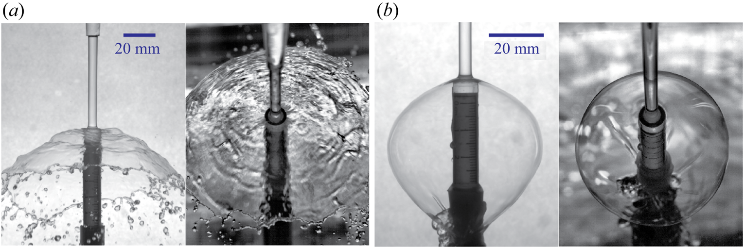
In the parametric space investigated in this study, the final regime observed with increasing flow rates is the downward bells. This regime could be classified into two sub-regimes: (a) open downward bells and (b) closed downward bells. Open downward bells are of an umbrella shape as seen in a representative case in figure 11(a). In most cases on increasing the flow rate, closed downward bells (as shown in figure 11b) are observed. Further details about these classic water bells can be found in Taylor (Reference Taylor1959a), Clanet (Reference Clanet2001) and Mohd et al. (Reference Mohd, Yadav and Das2022).
Regime IV: downward or classic water bells, illustrating two sub-regimes: (a) open downward for the case  $r_9\dot {m}_7$ and (b) closed downward for the case
 $r_5\dot {m}_5$. The left and right images in each panel display synchronized front and tilted top views, respectively (see the supplementary video, figure 11b).
5. Criteria for the formation of different regimes based on the dimensional analysis: regime diagrams
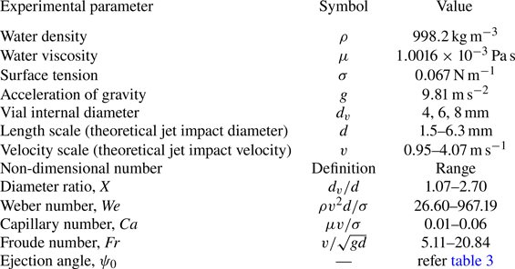
In this section we present a regime diagram in the non-dimensional parametric space for the formation of different types of water bells observed in experiments. The non-dimensional parameters are obtained using the Buckingham  ${\rm \pi}$ theorem as described in § 2 and given in (2.7). The parametric space in terms of non-dimensional numbers can be deduced from the experimental metric given in table 1. The ranges of the non-dimensional parameters obtained in the present experiments, along with the properties of the fluid used, are summarized in table 2.
Parametric space in terms of non-dimensional numbers (deduced from table 1) considered for the experiments in the present study.
Using the non-dimensional numbers – diameter ratio ( $X$), Weber number (
 $We$), capillary number (
 $Ca$) and Froude number (
 $Fr$) – six combinations of the parameter groups can be formed. The two-dimensional parameter spaces of (a)
 $X-Ca$, (b)
 $X-We$ and (c)
 $X-Fr$ (as shown in figure 12) exhibit demarcation of four regimes distinctly. The remaining two-dimensional parameter spaces of (d)
 $We-Ca$, (e)
 $Fr-Ca$ and ( f)
 $Fr-We$ do not indicate a similar demarcation of distinct water bell formation regimes. Thus, it is evident that the observed phenomenon in the current experimental arrangement that unifies all observed water bells has an unassailable dependence on the geometric parameter
 $X$, similar to dependencies observed in previous studies (Clanet Reference Clanet2000, Reference Clanet2001; Clanet & Villermaux Reference Clanet and Villermaux2002).
Regime diagram illustrating the observed dependence of the formation of different types of water bells on the governing non-dimensional parameters (a)  $X - Ca$, (b)
 $X - We$ and (c)
 $X - Fr$. The legend ‘puff-jc’, ‘puff-sc’ and ‘puff-vlnt’ denote the sub-regimes puffing bell-jet collision, self-collapsing puffing bells and violent collapse and formation of regime II, respectively.

Each of the regime diagrams shown in figure 12 show regime I: pre-sheet, regime II: puffing, regime III: steady upward and regime IV: downward water bells. The lines  $XX$,
 $YY$ and
 $ZZ$ are approximate boundaries between different regimes. The boundary
 $XX$ separates regime I and regime II. In the limit of the parameters explored in the current experimental campaign, the equation of the transition boundary between the regimes are given as follows. The functional dependence of line
 $XX$ with
 $Ca$,
 $We$ and
 $Fr$ can be given as
 $X = 28.12 Ca + 1.45$,
 $X =0.0027 We + 1.65$ and
 $X =0.0711 Fr + 1.46$, respectively. Notably, the other two boundaries,
 $YY$ and
 $ZZ$, depend only on the geometric parameter
 $X$ and are independent of the other dynamic parameters, i.e.
 $Ca$,
 $We$ and
 $Fr$. The equations of the boundaries
 $YY$ and
 $ZZ$ are found to be
 $X =1.77$ and
 $X = 1.5$, respectively.
At higher values of  $X$, the gap between the falling liquid jet and the vial wall is larger, and hence, the velocity of the ejecting fluid is lower resulting in the inertial forces being too small to overcome the effect of gravity and surface tension; consequently forming a blob in regime I. However, as the incoming mass flow rate increases for a given value of
 $X$ (moving horizontally in figure 12 in regime I), the ejection velocity as well as the inertial forces increase relatively, which leads to the formation of the liquid sheet and completes the transition to regime II. Also in regime I, for higher
 $X$, because of the wider gap between the incoming jet and the vial wall, a higher
 $\dot {m}$ is required to create sufficient velocity for ejecting the sheet, making the transition from regime I to regime II occur at larger
 $We$,
 $Ca$ and
 $Fr$. The other two transition boundaries,
 $YY$ and
 $ZZ$, show a peculiar transition nature since they primarily depend on
 $X$. Hence, fixing the value of
 $X$ within regimes II, III and IV and moving horizontally does not encounter a regime transition . On the other hand, moving along a vertical line for a fixed value of parameters
 $Ca$,
 $We$ and
 $Fr$, the regimes transition from regime I to regime IV is observed.
The transition from one structure to another primarily depends on two parameters: the ejection velocity,  $v_0$, and the ejection angle,
 $\psi _0$. The transition from regime I to regime II is largely controlled by
 $v_0$, where
 $\psi _0$ is nearly
 $90^{\circ }$ (figure 5) along the boundary XX. As the gap decreases on increasing
 $\dot {m}$,
 $\psi _0$ changes, resulting in different types of water bells observed in regimes I, II and III. To understand this further, we conducted a series of experiments with increasing
 $\dot {m}$ that resulted from the transition of regime I to regime IV (table 5). Note that
 $We$ changes substantially whereas
 $Ca$ and
 $Fr$ remain nearly unchanged, representing a vertical line in figure 12(a). For a fixed value of vertical distance between the vial and nozzle exit (
 $h_{nv}$) and vial diameter (
 $d_v$), increasing the mass flow rate (
 $\dot {m}$) increases the diameter and velocity of the jet at impact resulting in lower values of
 $X$ and ejection angle (
 $\psi _0$); consequently the water bells transition from regime I to IV (table 5).
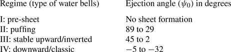
For upward (figure 13a) and downward (figure 13b) bells,  $\psi _0$ is taken positive and negative, respectively. In general, for regimes II to IV,
 $\psi _0$ decreases from 89 to
 $-$32 (table 3). An overlap in the ejection angle can be observed between regime II and regime III. Note that the angles are measured manually by tracing the edge of the water bell near the ejection point in the acquired experimental images in Matlab
 . The angles provided in tables 3 and 5 are the average values, and the standard deviation was found within
 $2^\circ$.
A schematic illustrating the CV used in the analysis for (a) upward and (b) downward bell (analysis given in Appendix D) cases, respectively.

Range of  $\psi _0$ for different regimes observed on the regime diagram.
To understand how the ejection angle changes, we derived a relation of the dependence of ejection angle with  $We$,
 $Ca$ and
 $Fr$ in the next section. It helps us to explain the regime diagram better. A detailed analysis of the fluid flow behaviour in the vial mouth may illustrate the same, which is not within the scope of the present work. However, the qualitative nature of the flow field is obtained using particle visualization that illustrates how the flow inside the vial controls the ejection angle (see Appendix C, figure 20).
6. Modelling the bell ejection angle ( $\psi _0$)

We obtain the ejection angle, both experimentally and theoretically and compare them to establish the validity of the theoretical analysis. The ejection angle is also used for trajectory prediction in the next section. To find a theoretical expression for the ejection angle, a CV analysis has been performed. Two suitable CVs for upwards and downward bells have been chosen. The CV analysis for the upward bells is presented below while the analysis for the downward bells is provided in Appendix D. Note that Clanet (Reference Clanet2001) also derived an equation for predicting  $\psi _0$ at the edge of the impactor disc. However, due to different boundary conditions in the current experiment and Clanet's work, his equation is not applicable to the present problem. A detailed comparison of the two models is presented in Appendix D.
In the entire analysis it is assumed that the flow is steady as observed in upward or downward moving stable water bells. However, even a quasi-steady assumption is valid for puffing water bells as will be discussed later. A schematic of the CV and relevant forces acting on it are shown in figure 13. A cylindrical coordinate system with the origin at the centre of the vial mouth has been chosen. The inlet is chosen at a height of  $d$ to avoid the curvature effect due to surface tension at the vial mouth. The schematic shows the forces and dimensions in the plane passing through the cylindrical axis. The problem is considered to be axisymmetric based on the observations of the water sheet structure formed and particle flow visualization (see Appendix C). The plausible direction of the viscous shear stress has been chosen based on the upward moving fluid layer adjacent to the vial wall near the vial mouth, confirmed by the particle flow visualization presented in Appendix C. Nevertheless, the direction and magnitude of the net shear force (
 $F_s$) due to viscous shear stress would be dictated by the solution as
 $F_s$ is treated as an unknown in the analysis. The diameter,
 $d$, and velocity,
 $v$, are defined for the incoming free jet at the vial mouth location and considered to remain the same in the presence of the vial.
The continuity equation can be written as
 \begin{equation} \dot{m}=\rho v_{1}A_{1}= \rho A v =\rho v_{2} \cos \psi_0 A_{2}, \end{equation}
where  $A_1$,
 $A_2$ and
 $A$ are the area at the inlet, outlet and vial mouth, respectively.
Conservation of linear momentum in the  $z$ direction yields
 \begin{equation} \sum F_{surf} + \sum F_b= \rho A_{1} v_{1}^2 + \rho A_{2} v_2^2 \sin \psi_0 \cos \psi_0, \end{equation}
where  $F_{surf}$ and
 $F_b$ denote the surface and body forces, respectively. We have
 \begin{equation} \sum F_{surf} = F_{s} + F_{pres} + F_{\sigma}| _{in} + F_{\sigma}| _{out}, \end{equation}
where  $F_{pres} = (p_a + \rho h_v g)A_v - (p_a + 2\sigma /d_1 ) A_1 - p_a(A_v - A_1)$, with
 $p_a$ being the atmospheric pressure,
 $F_{\sigma }| _{in} ={\rm \pi} d_1 \sigma$ and
 $F_{\sigma }|_{out}=F_{\sigma }| _{out1} + F_{\sigma }| _{out2}$ (see figure 13a). The surface tension forces at the outlet are
 \begin{equation} F_{\sigma}| _{out1} = F_{\sigma}| _{out2} = {\rm \pi}d_v \sigma \sin \psi_0. \end{equation}
Substituting the respective force term in the above equation leads to
 \begin{equation} \sum F_{surf} = F_{s} + \left(\rho h_v g A_v -\frac{{\rm \pi} d_1 \sigma}{2}\right) + {\rm \pi}d_1 \sigma + 2 {\rm \pi}d_v \sigma \sin \psi_0. \end{equation}
Furthermore,
 \begin{equation} \sum F_b = \int
_{{-}\!\!\!\!V _1} \rho g \,{\rm d}
{-}\!\!\!\!V + \int _{{-}\!\!\!\!V _2}
\rho g \,{\rm d} {-}\!\!\!\!V,
\end{equation}
where  ${-}\!\!\!\!V _1$ is the volume inside the vial and
 ${-}\!\!\!\!V _2$ is the volume between the inlet and the vial mouth. The second term in (6.6) is calculated assuming the incoming jet falls freely in the absence of the vial. The elemental volume for performing the integration is shown in figure 13(a). Integrating (6.6), we obtain
 \begin{align} \sum F_b &={-}\rho g A_v h_v + \frac{\rm \pi}{4} d^2 \int _{0} ^d \frac{d\eta}{\sqrt{1- \dfrac{2g \eta}{v^2}}}\rho g \nonumber\\ &={-}\rho A_v h_v g - \frac{{\rm \pi} \rho v^2 d^2}{4}\left(1 - \sqrt{1- \frac{2gd}{v^2}}\right), \end{align}
where  $A_v$ and
 $h_v$ denote the internal cross-sectional area and height of the vial, respectively. Substituting
 $\sum F_{surf}$ and
 $\sum F_b$ into (6.2) and using (6.1) we obtain the final relation as
 \begin{align} F_{s} +\frac{{\rm \pi} d_1 \sigma}{2} + 2 {\rm \pi}d_v \sigma \sin \psi_0 - \frac{{\rm \pi} \rho v^2 d^2}{4}\left(1 - \sqrt{1- \frac{2gd}{v^2}}\right)= \rho A_{1} v_{1} ^2 \left(1 + \frac{v_2}{v_1} \sin \psi_0 \right). \end{align}
Neglecting the influence of air drag and employing Bernoulli's equation (see Marmottant et al. Reference Marmottant, Villermaux and Clanet2000) along both the central and free surface streamlines within the incoming jet from the inlet to the vial mouth, it is established that  $v_2 = v$. Therefore, (6.8) can be written as
 \begin{align} {\rm \pi}d \sigma \left[\frac{F_s}{{\rm \pi} d \sigma} + \frac{d_1}{2d} + 2\frac{d_v}{d} \sin \psi_0 - \frac{\rho v^2 d}{4\sigma} \left(1 - \sqrt{1- \frac{2gd}{v^2}}\right) \right] = \rho A v(v_1 +v \sin \psi_0). \end{align}
The above equation can be written in non-dimensional form as
 \begin{equation} \frac{F_s}{{\rm \pi} d \sigma} + \frac{d_1}{2d} + 2 X \sin \psi_0 - \frac{We}{4} \left(1 - \sqrt{1- \frac{2}{Fr^2}}\right)= \frac{We}{4} \left(\frac{v_1}{v} + \sin \psi_0\right). \end{equation}
We obtain the value of  $v_1/v$ in the above equation using (2.3). Note that the notations
 $v_n$ and
 $v(z)$ in (2.3) are the same as
 $v_1$ and
 $v$, respectively. Thus,
 \begin{equation} \left(\frac{v_1}{v}\right)^2 = 1 - \frac{2}{Fr^2} + \frac{4}{We}\left( 1 - \frac{d}{d_1}\right). \end{equation}
Since  $d/d_1 \approx 1$, the last term in the equation is neglected, resulting in
 $v_1/v = \sqrt {1 - 2/Fr^2}$. Also, from continuity we can write
 $d_1/d=(1 - 2/Fr^2)^{-1/4}$. Substituting the values of
 $v_1/v$ and
 $d_1/d$ into (6.10), the final non-dimensional expression is obtained as
 \begin{equation} \widetilde{F_s} + \frac{1}{2}\left(1 - \frac{2}{Fr^2}\right)^{-({1}/{4})} + 2 X \sin \psi_0 - \frac{We}{4}= \frac{We}{4} \sin \psi_0, \end{equation}
where  $\widetilde {F_s} = F_s/{\rm \pi} d \sigma$ is the non-dimensional viscous shear force.
All the quantities in (6.12) except for  $\widetilde {F_{s}}$ are known from the experiment for each run as the ejection angle (
 $\psi _0$) is extracted from the water bell images. The estimated values of viscous shear force,
 $\widetilde {F_{s}}$, are used to model it in terms of
 $Ca$ as
 $Ca$ is the ratio of viscous force and surface tension force. The variation of
 $\widetilde {F_{s}}$ with
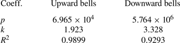
 $Ca$ is shown in figures 14(a) and 14(b), respectively, for upward and downward water bells. It can be observed that power law fitting of the data is quite accurate for upward water bells and reasonable for downward ones. Using the power law given as
 \begin{equation} \widetilde{F_s} = {p {Ca}^k,} \end{equation}
the fitting coefficients  $p$ and
 $k$ are evaluated from the experimental data as given in table 4.
Variation of the estimated  $\widetilde {F_s}$ for different experiments, showing its power law dependence on
 $Ca$ using (a) (6.12) for upward water bells in regime II and regime III, and (b) (D2) of Appendix D for downward bells in regime IV.

Coefficients of the power law fit for the modelling of shear force,  $\widetilde {F_s}$, as given in (6.13).
Comparison of the theoretically calculated and experimentally obtained  $\psi _0$ with increasing mass flow rate for a particular case
 $r_{10}\dot {m}_*$ (as given in table 1). The notation in the ‘bell type’ column refers to different types of bells occurring in regimes I–IV.

By substituting  $\widetilde {F_s}$ into (6.12), the semi-empirical expression for predicting the ejection angle in terms of
 $We$,
 $Ca$ and
 $Fr$ is given as
 \begin{equation} \psi_0 = \sin^{{-}1}\left\{\frac{- p Ca^k - \dfrac{1}{2} \left(1 - \dfrac{2}{Fr^2}\right)^{-({1}/{4})} + \dfrac{We}{4} }{2 \chi - \dfrac{We}{4}}\right\}, \end{equation}
where
 \begin{equation} \chi =
\left\{\begin{array}{@{}ll@{}} X =\dfrac{\text{`ejection sheet
diameter'}}{d} & \text{(Upward bells)},\\
X + 2 \widetilde{t_w}=\dfrac{\text{`ejection
sheet diameter'}}{d} & \text{(Downward bells; see Appendix D)}.
\end{array}\right.
\end{equation}
Note that, for the downward bell, a new term  $\widetilde {t_w} = t_w / d$ appears as the lip thickness,
 $t_w$, of the vial is considered in the analysis. The ‘ejection sheet diameter’ for upward and downward water bells is
 $d_v$ and
 $d_v + 2t_w$, respectively. Consequently, (6.14) serves as a unified equation for predicting
 $\psi _0$, wherein the geometric parameter
 $\chi$ is defined by (6.15).
Given  $5.11< Fr<20.84$ in the present experiment, the term
 $1 - (2/Fr^2)^{-0.25} \approx 1$ in (6.14) and, hence, can be neglected. Considering
 $Ca \approx 0.02$ and employing values
 ${p = 6.965 \times 10^4}$ and
 $k = 1.923$ from table 4, the term
 $pCa^k \approx 38$. Furthermore, with
 $We/4 \approx 20$ (figure 12b), the numerator
 $-pCa^k + We/4$ becomes negative. Similarly, within the range
 $1.5 < \chi <3$, the denominator evaluates to
 $2\chi -We/4 <0$ confirming
 $\psi _0 >0$ for upward bells. For downward bells, taking
 $p=5.764 \times 10^6$ and
 $k=3.328$ along with
 $Ca \approx 0.03$, the term
 $pCa^k \approx 49$. Given
 $We/4 \approx 75$, the numerator becomes positive. Consequently, with
 $2\chi = 2(X+ 2\widetilde {t_w}) \approx 2(1.5 + 2 \times 0.25) \approx 4$, the denominator
 $2\chi - We/4$ with
 $We/4 \approx 75$ turns negative, ensuring
 $\psi _0<0$ for a downward bell. Furthermore, for upwards bells to maintain
 $\psi _0 >0$, the denominator necessitates
 $We>8\chi$, resulting in
 $We> 24$, consistent with the regime diagram shown in figure 12. Similarly, for downward bells, the constrain
 $\psi _0<0$ establishes the requirement
 $We >20$, a validation also supported by the regime diagram in figure 12.
Finally, to show the predictive capability of the semi-empirical expression, we plot the experimentally obtained ejection angle,  $\psi _0$, and those obtained using the expression (6.14). Figure 15(a) shows the comparison for the upward bells of regime II and regime III. The tick labels on the
 $x$ axis represent the case identifications of each data point, alternately displayed at the bottom and top. Here, we observe that a simple CV-based semi-empirical model predicts the relative angle changes between the cases reasonably well. For regime IV: downwards, a separate CV analysis is performed as the effect of the vial wall thickness needs to be taken into consideration. The resulting
 $\psi _0$ predictions are compared with the
 $\psi _0$ obtained from experiments in figure 15(b). The predictions for the downward bells also align satisfactorily with the experiments, albeit with a larger scatter in the data compared with the upward cases. This variance in case of downward bells may be attributed to the zero pressure difference assumption between the inside and outside of closed downward bells during the CV analysis. Contrarily, the angle measured from the experimental images might have been affected by the presence of pressure differences. Note that all other observed bell types across the four regimes are open, ensuring a zero pressure difference scenario.
Comparison of predicted and experimentally obtained ejection angles for (a) upward and (b) downward water bells.

7. Modelling the puffing bells: comparison of experiments and theory
As explained earlier in § 4.2, regime II: puffing, is characterized by the periodic formation and destruction of the upward bells. Here, we investigate the trajectory and the rise time of the puffing water bells.
7.1. Puffing bell trajectory
In our previous study (Mohd et al. Reference Mohd, Yadav and Das2022), we found that the bell profile in the case of steady upwards and downwards bells can be predicted by the solution of the theoretical equation (2.2) obtained from the balance of gravity, inertial, pressure and surface tension forces. Here, in case of puffing bells, the curve traced by the moving bell rim is also compared with the theoretical equation (2.2), assuming the puffing bell trajectory to be quasi-steady. The instantaneous rising water bell images are first time averaged to get the mean bell-shaped puffing profile (figure 16). The trajectory of the puffing bell rim obtained using averaging is free from small-scale fluctuations caused by the instabilities. The instantaneous puffing bell trajectory compares well with the time-averaged puffing trajectory over five puffing cycles for case  $r_1\dot {m}_3$, as shown in figure 16, hence validating the assumption of a quasi-steady puffing bell rise. The extracted experimental bell profiles are plotted along with the theoretically calculated ones as shown in figures 17(a), 17(b) and 17(c), corresponding to the vial diameters of 8, 6 and 4 mm, respectively. The theoretically calculated bell profiles agree well with the experimentally traced ones. Note that the bell profile near the jet collapsing point cannot be extracted from the experimental images since the jet collapse blurs the mean profile when time averaged. This shows that the puffing profile behaves similarly to the stable upward and downward bells except that they collapse on the jet and, hence, give rise to the periodic generation and destruction, referred to as a puffing cycle in this paper. Puffing water bells may alternatively be understood as upward-closed water bells since, when time averaged, they formed upward-closed bell shapes just like downward-closed bells or classical water bells. However, as they close on the incoming jet, which is the cause of their formation, they destroy themselves, thereby preventing the formation of a stable upward-closed water bell.
Verification of the quasi-steady assumption by comparing the instantaneous puffing bell trajectories with the time-averaged trajectory, over multiple puffing cycles, for the case  $r_1\dot {m}_3$. The dashed blue line is the time-averaged puffing bell trajectory, which closely aligns with steady water bells (see figure 17). The instantaneous images are captured at times (ms): (a) 26 (0.09), (b) 66 (0.22), (c) 96 (0.32) and (d) 116 (0.39), where the time in the parentheses is normalized to the puffing cycle period.

Puffing water bell profiles for vial diameter,  $d_v$, of (a) 8 mm, (b) 6 mm and (c) 4 mm, where the legend denotes the case identification in table 1. Symbols and solid lines depict the time-averaged profiles from experiments and numerical integration of (2.2) based on steady-state theory, respectively.

7.2. Puffing bell rise time
Rise time is defined as the duration taken by the rim of the ascending bell sheet from its formation at the vial mouth to its intersection with the incoming jet (see figure 4). Both surface tension and gravity forces act to decrease the fluid's velocity as it travels along the sheet, leading to mass accumulation and thickening at the sheet's edge, thereby forming the rim. Understanding the detailed dynamics and fragmentation of the rim is beyond the scope of the present work. Nonetheless, due to its influence on the rise time in a puffing cycle and, consequently, on the puffing frequency it has been modelled using simple CV analysis as given below.
Consider a rising puffing bell rim as shown in figure 18, the bell rim traces the trajectory akin to a quasi-steady water bell as compared in figure 17. The coordinate system is chosen as defined earlier in figure 1 of § 2. The unsteady puffing bell rim can be analysed assuming a CV around the rim as shown in the inset of the figure 18. Neglecting the formation of ligaments (figures 7(a), 8(a) and 8(b)) that shed in the form of droplets and a residual hanging sheet (figure 16a,b), the rim can be characterized by its mass,  $m_r$, and velocity,
 $v_r$, at any arbitrary time instance,
 $t$. Also at this instance, the rim is at an arc length
 $s_r (t)$ from the vial mouth. The two primary forces acting upon the rim are surface tension and gravity, which balance the inertial force. Using continuity, the thickness of the water bell sheet
 $h$ (Taylor Reference Taylor1959a) at the rim base can be written as
 \begin{equation} h=\frac{\dot{m}}{2 {\rm \pi}r_r v_b \rho}, \end{equation}
where  $v_b$ is the fluid velocity in the sheet at the rim base. Considering the non-inertial CV attached to the rim as shown in the inset of figure 18, mass conservation gives
 \begin{equation} 0=\frac{{\rm d} m_r}{{\rm d} t} + \int_{S} - \rho (v_b-v_r)\,{\rm d} S, \end{equation}
where  $dS = d(2 {\rm \pi}r_r h)$, taking
 $h<< r_r$. Thus,
 \begin{equation} \frac{{\rm d} m_r}{{\rm d} t} = \dot{m} \left(1 - \frac{v_r}{v_b}\right). \end{equation}
The linear momentum balance in the tangential direction on the rim yields
 \begin{equation} -2 {\rm \pi}(2r +h) \sigma - m_r g \sin \psi - \frac{{\rm d} v_r}{{\rm d} t} m_r={-}\frac{\dot{m}}{v_b} (v_b - v_r)^2. \end{equation}
A schematic showing the water bell during a puffing cycle of regime II along with the CV attached to the rim. Inset shows an enlarged view of the CV.

Neglecting the acceleration of the rim ( ${\rm d} v_r/{\rm d} t$) and gravitational forces, the Taylor–Culick velocity for the classical configuration (Taylor Reference Taylor1959b; Culick Reference Culick1960; Bremond et al. Reference Bremond, Clanet and Villermaux2007; Sanjay et al. Reference Sanjay, Sen, Kant and Lohse2022) can be recovered. Assuming
 $2r+h \approx 2r$ in (7.4) and using (7.1), the Taylor–Culick velocity is given as
 $v_b-v_r=\sqrt {(2\sigma /h\rho )}$. Equation (7.4) is further modified using (7.1) as
 \begin{equation} \frac{{\rm d} v_r}{{\rm d} t} =\frac{1}{m_r} \left[\dot{m} v_b \left(1 - \frac{v_r}{v_b}\right)^2 - 2 {\rm \pi}(2r +h) \sigma - m_r g \sin \psi \right]. \end{equation}
The trajectory of the puffing bell rim is known, which is obtained by solving (2.2) for a steady upwards water bell and is denoted by  $r=f(z)$. The slope of
 $f(z)$ at any
 $z$ location can be denoted by
 ${\rm d} z/{\rm d} r = \tan \psi = g(z)$. Functions
 $f$ and
 $g$ denote a relation that can be numerically interpolated. Therefore, a system of equations, as given below, could be solved for
 $m_r (r,z,t)$ and
 $v_r (r,z,t)$:
 \begin{equation} \left.\begin{array}{@{}l@{}}
r=f(z);\quad \psi=\tan^{{-}1}(g(z));\quad v_b=\sqrt{v_0 ^2
-2gz}; \\ \dfrac{{\rm d} m_r}{{\rm d} t} = \dot{m} \left(1
- \dfrac{v_r}{v_b}\right); \\ \dfrac{{\rm d} v_r}{{\rm d}
t} = \dfrac{1}{m_r} \left[\dot{m} v_b \left(1 -
\dfrac{v_r}{v_b}\right)^2 - 2 {\rm \pi}(2r +h) \sigma - m_r g
\sin \psi \right]; \\ \dfrac{{\rm d} z_r}{{\rm d}
t}=\dfrac{v_r}{\sqrt{(1 + \left(\dfrac{{\rm d} r}{{\rm d}
z}\right)^2 )}}; \\ \mbox{Initial conditions (ICs)}: \\
\quad m_r(r = d_v/2,z = 0)=0;\quad v_r(r = d_v/2,z = 0)=0;\quad
z_r=0. \end{array}\right\}
\end{equation}
This system of equations is solved using Matlab's built-in ‘ode15s’ routine (Shampine & Reichelt Reference Shampine and Reichelt1997), which is an implicit and adaptive step size solver for stiff ordinary differential equations. The zero division error due to the boundary condition  $m_r = 0$ is circumvented using a very small value of
 $1 \times 10^{-6}$ instead.
From the solution,  $z_r(t)$, the rise time of the puffing bell rim was extracted. A direct comparison of the theoretical and experimental rim rise time is provided in figure 19 and a good agreement between the two can be observed. The time has been non-dimensionalized using
 $d_v$ and
 $v_0$. The top and bottom
 $x$-axis tick labels in figure 19 show the case identifications of the selected puffing cases in alternating order. However, it can be noticed that the model consistently underpredicts the rise time in comparison to the experiments. This observation is consistent with our initial assumption of no-ligament formation on the rim. The ligaments formed on the rim ultimately fragment into the droplets leading to the mass shedding. The cause for the underprediction of the rise time could be attributed to the fact that we did not consider the mass shedding from the rim, resulting in increased momentum influx from the sheet into the rim, in the current model.
Comparison of non-dimensionalized experimental and theoretical puffing bell rise times obtained by numerical integration of (7.6).

8. Conclusions
We have investigated the formation of different types of spectacular water sheet structures known as water bells, occurring when a liquid jet plunges on a vial filled with the same liquid. The approach generalizes different types of water bells, being generated using the same boundary conditions and paves the way for developing a unified experimental and theoretical framework for modelling. In the present study, experimental data demarcates different regimes and identify the non-dimensional parameters important to draw the regime diagrams. The types of water bell structures observed are classified into four regimes: regime I: pre-sheet, regime II: puffing, regime III: stable upwards and regime IV: downwards.
In regime I: pre-sheet (figure 3), a fluid blob is formed at the vial mouth and the water from the blob drips down the external wall of the vial. In regime II: puffing, a periodic formation and destruction of upward-rising water bells is observed. The term ‘puffing water bells’ is coined in this paper to describe these fascinating water sheet features that have been unreported in the literature. Here, we observed three different sub-regimes, namely puffing bell-jet collision (figure 4), self-collapsing puffing bells (figure 8), and violent collapse and formation (figure 9). In case of a puffing bell-jet collision, bells rise upward and curve inward due to surface tension to collide with the incoming jet (figure 4). In comparison to the typical puffing cycle, for comparatively low flow rates, the ejecting sheet is almost vertical ( $\psi _0 \approx 90^{\circ }$) and forms relatively high-frequency puffing water bells (figure 5). For a particular case, the disintegration process of the puffing water bell sheets revealed a mechanism responsible for the formation of the high-speed droplets moving in the upward direction besides the regular droplets formed from the rim fragmentation (figure 6c,h). This mechanism gets activated as the ejection velocity,
 $v_0$, decreases while the rising water bell strikes the incoming jet at the collision point. At some parametric ranges, the disintegration of the puffing sheet displays a peculiar nature (figure 7) where a bell is observed to exist even after the incoming jet is completely detached from the vial mouth (figure 7c). For the sub-regime self-collapsing puffing bells, the maximum bell diameter is relatively large as compared with the puffing bell-jet collision case. When the sheet starts to contract back towards the jet, the rim thickness increases considerably (figure 8b) to satisfy the conservation of mass. This increases the mass of the rim, leading to the sheet collapse (figure 8c). In the sub-regime referred to as violent collapse and formation, a periodic highly transient fluid sheet, ejecting almost vertically, is seen to be forming, which gets fragmented into randomly moving droplets of different sizes (figure 9).
Furthermore, we described regime III: steady upward water bells (figure 10) where the film front continuously breaks into droplets after ascending a certain height and then falling outside the bell, hence maintaining the steady nature of the water bells. Increasing the mass flow rate further led to the observance of regime IV: downward or classic water bells, which is classified into two sub-regimes: open downward bells (figure 11a) and closed downward bells (figure 11b).
The trajectory of the water bell depends upon the initial conditions: the ejection velocity,  $v_0$, and ejection angle,
 $\psi _0$, of the governing equation (2.2). The important non-dimensional numbers affecting
 $v_0$ and
 $\psi _0$ are diameter ratio (
 $X$), capillary number (
 $Ca$), Weber number (
 $We$) and Froude number (
 $Fr$), obtained using the Buckingham
 ${\rm \pi}$ theorem as given in (2.7). The two-dimensional parameter spaces of
 $X-Ca$ (figure 12a),
 $X-We$ (figure 12b) and
 $X-Fr$ (figure 12c) exhibit demarcation of four regimes distinctly, whereas the remaining two-dimensional parameter spaces of
 $We-Ca$,
 $Fr-Ca$ and
 $Fr-We$ do not indicate a similar demarcation of distinct water bell formation regimes. The study found that the observed phenomenon is strongly dependent on the geometric parameter
 $\chi$, analogous to the geometric parameters in earlier studies (Clanet Reference Clanet2000, Reference Clanet2001; Clanet & Villermaux Reference Clanet and Villermaux2002).
We determined the ejection angle through both experimental and theoretical means, comparing them to validate our theoretical analysis. A theoretical expression for the ejection angle is derived through a CV analysis conducted for both upward and downward bells. The CV analysis resulted in a semi-empirical expression for the ejection angle, as given in (6.14). Equation (6.14) serves as a unified equation for predicting  $\psi _0$, whereas the geometric parameter
 $\chi$ is defined by (6.15). While the regime diagrams and the semi-empirical formula reasonably predict the types of water bells, which is the primary focus of this paper, they lack detailed information about the flow field at the vial mouth. Our observations from the particle visualization indicate that the incoming water jet exhibits a partial deflection from the vial mouth while also partly penetrating inside. Furthermore, we observed distinct differences in streamline patterns at the vial mouth's periphery, where they converge in upward and downward directions for the respective upward (figure 20a) and downward (figure 20b) water bells.
Streamline pattern as obtained from the time average of particle visualization near the vial mouth for (a) regime III: upward water bells and (b) regime IV: downward water bells (see the supplementary video, figure 20a).

The curve traced by the puffing bell is also compared with the theoretical equation (2.2), assuming the puffing bell trajectory to be quasi-steady. The theoretically calculated bell profiles agree well with the experimentally traced ones. It shows that the puffing profile behaves similarly to the stable upward and downward bells, except that they collapse on the jet, which results in periodic generation and destruction. Puffing water bells may alternatively be understood as upward-closed water bells since, when averaged, they formed upward-closed bell shapes just like downward-closed bells or classical water bells. For the puffing cases, a theoretical prediction of the rise time (7.6) is also given using a CV analysis on the rim, including the gravity forces previously solved with inertial and surface tension forces only for the downward bells produced from different experimental boundary conditions (Clanet Reference Clanet2001; Clanet & Villermaux Reference Clanet and Villermaux2002). A direct comparison of the theoretical and experimental rim rise time shows good agreement. However, it can be noticed that the model consistently underpredicts the rise time in comparison to the experiments due to our assumption of no-ligament formation on the rim that leads to the mass shedding. This model can be further improved in future studies by considering the mass shedding through the rim and could provide a method for precise control of the droplet size and rate of fragmentation. Various liquid sheet structures discovered in the current study could find possible applications in the field of liquid fuel atomization (Dombrowski & Hooper Reference Dombrowski and Hooper1964; Lasheras & Hopfinger Reference Lasheras and Hopfinger2000; Sweeney & Frederick Reference Sweeney and Frederick2016) for liquid rocket engines as well as in liquid sheet radiators (Chubb et al. Reference Chubb, Calfo, McConley, McMaster and Afjeh1994) for space power systems. Additionally, the regime diagrams could be used to design fascinating public displays of water bells.
Supplementary movies
Supplementary movies are available at https://doi.org/10.1017/jfm.2024.928.
Acknowledgements
The authors acknowledge Mr D. Poddar and Mr D. Singh Rawat for verifying algebraic calculations.
Funding
The authors acknowledge partial support from DST-FIST, India.
Declaration of interests
The authors report no conflict of interest.
Data availability statement
The data that support the findings of this study are available within the article and in the supplementary material.
Appendix A. Experimental parameters for pre-sheet cases
The pre-sheet regime was explored in detail for the experimental cases as given in table 6.
Experimental parameters – nozzle diameter ( $d_n$), vial diameter (
 $d_v$), height difference count (
 $h$), value of height difference between nozzle and vial (
 $h_{nv}$), and mass flow rate (
 $\dot {m}$) for the pre-sheet formation cases.
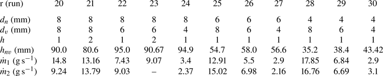
Appendix B. Details of particle flow visualization
A particle flow visualization was performed in the vial with details given as follows. A diode-pumped solid-state continuous laser of wavelength 532 nm and power of 1 W was used to illuminate the meridian plane of the vial. The circular Gaussian beam of the continuous laser was transformed into a thin sheet, of approximately 1 mm thick, utilizing sheet forming optics comprising two spherical and one cylindrical lens. The polyamide seeding particles of  $50\,\mathrm{\mu } {\rm m}$ and 1.03 g cm
 $^{-3}$ density are mixed thoroughly in the Mariot's bottle reservoir. To acquire the images akin to time-resolved particle image velocimetry (PIV) of the flow inside the vial, the camera frame rate was set at 800 fps. However, due to the large flow velocity, the particle images get blurred at the vial mouth. Therefore, the PIV images at the vial mouth were acquired using cropped frames, thereby increasing the fps to 3035. After performing the time-resolved PIV analysis, the instantaneous velocity fields were averaged to get a quantitative description of the flow field at the vial mouth. For the PIV computation, a MATLAB
 based open-source tool PIVlab (Thielicke & Stamhuis Reference Thielicke and Stamhuis2014; Thielicke & Sonntag Reference Thielicke and Sonntag2021) is used. Within PIVlab, Contrast limited adaptive histogram equalization (CLAHE) was applied with a window size of 64 to correct image contrast. Additionally, a two-dimensional adaptive de-noising filter, Weiner, with a 3-pixel window size, was used to remove noise. The cross-correlation was computed using the fast Fourier transform-based algorithm with window deformation. This cross-correlation analysis comprised two passes, employing an interrogation area of
 $128 \times 128$ and
 $64 \times 64$, respectively, with a 50 % overlap in each pass. For the sub-pixel estimate of the cross-correlation peak, a Gaussian fit was used during the analysis.
Appendix C. Flow field inside the vial
From previous studies and the current experiments, it is well established that the initial conditions, i.e. ejection velocity ( $v_0$) and ejection angle (
 $\psi _0$), determine the nature of the water bell. Therefore, we seek an investigation of how the flow near the vial mouth, in the present experimental arrangement, affects the initial conditions leading to the formation of different types of water bells. Our quest for the cause of this unified phenomenon leads to the visualization of the flow field at the vial mouth. We formulate two questions: first, is the flow initially penetrating the vial and then coming out in the form of an annular sheet? Second, is the streamline pattern in the vicinity of the vial mouth different for different regimes of water bells? The particle visualization as described in § 3 was carried out. A typical streamline pattern, depicted in figure 20, is obtained by averaging 3099 snapshots acquired at 3035 fps of the flow field at the vial mouth.
From the particle motion (see the supplementary video, figure 20a) and the averaged streamline from the PIV analysis, we discern that the incoming fluid partially penetrates the vial and does not completely deflect from the vial mouth, thus addressing the first question. Moreover, the incoming jet streamlines near the vial periphery bend upstream, converging to form a high-velocity ejection sheet, whereas those near the central jet continue downward, contributing to the bulk three-dimensional motion inside the vial. Examining the central region of vial mouth in figures 20(a) and 20(b) for regime III and regime IV, respectively, we note qualitatively identical streamline patterns. However, the pattern changes quite significantly near the peripheral region to form stable upwards and downwards ejecting sheets. Probably, an accurate quantitative information on the flow field is required for precise diagnostics of the flow near the vial periphery.
In figure 21 a schematic depicting the flow field in the meridian plane inside the vial at an intermediate arbitrary time instance is presented. The incoming fluid near the centre of the jet at the vial mouth moves downward into the vial, while a significant portion is deflected back into the ejection sheet. The fluid that is getting injected near the centre of the incoming jet provides the necessary energy for the fluid motion inside the vial. To conserve the mass inside the vial, the fluid returns from the bottom towards the mouth, near the periphery of the vial, and mixes with the outgoing fluid of the ejecting sheet. However, this internal motion is unsteady and three dimensional. This observation concludes that the incoming jet fluid is interacting with the vial fluid through random vortical structures with decreased velocity as we go down towards the bottom.
Instantaneous streamline pattern superimposed with velocity vectors obtained from the particle visualization, inside the vial, at an arbitrary time instance. The incoming jet is impinging on the vial mouth on the left-hand side of the figure. (see the supplementary video, figure 21).

The velocity of the vortical structure decreases by orders of magnitude as we move toward the vial bottom (figure 21). In the experiments, the total depth of the vials was taken as 10 times the vial diameter,  $d_v$. Figure 21 shows that the velocity field at a depth of 2.9
 $d_v$ becomes negligible. Thus, the depth of the vials used in this study is sufficiently large, and increasing it further would not affect the ejection sheet dynamics at the vial mouth. A detailed analysis of the shallower-vial depth on the water bells is beyond the scope of the present investigation and could be explored in future studies.
Appendix D. Control volume analysis for downward bells
Unlike the upward bell CV analysis, the ejecting fluid exits the outlet after flowing over the vial lip with an ejection angle ( $\psi _0$) as depicted in figure 13(b). Notably, the shear force (
 $F_s$) is governed differently compared with the upward bells due to the additional no-slip surface, provided by the vial lip with a thickness
 $t_w$. Consequently, a distinct CV (figure 13b) needs to be chosen for the downward bells to perform CV analysis near the vial mouth with the aim of calculating
 $\psi _0$. A cylindrical coordinate system with an origin at the centre of the vial mouth along with the axisymmetric problem formulation has been chosen, similar to the upward bell CV analysis. The continuity (6.1) and conservation of linear momentum (6.2) equations remain identical to those in the upward water bell CV analysis. Here
 $F_{surf}$ is calculated as given by (6.3), with the exception of the last term, which differs for downward bells and is calculated using
 \begin{equation} F_{\sigma}| _{out1} = F_{\sigma}| _{out2} = {\rm \pi}(d_v+2t_w) \sigma \sin \psi_0. \end{equation}
The body forces,  $F_b$, are determined using (6.7). Substituting
 $\sum F_{surf}$ and
 $\sum F_b$ in (6.2) and employing algebraic manipulation, analogous to that described in § 6 utilizing (6.1), results in
 \begin{equation} \widetilde{F_s} + \frac{1}{2}\left(1 - \frac{2}{Fr^2}\right)^{-({1}/{4})} + 2 (X + 2\widetilde{t_w} )\sin \psi_0 - \frac{We}{4} = \frac{We}{4} \sin \psi_0. \end{equation}
A similar expression for the prediction of  $\psi _0$ for the jet impinging on a solid deflector disc unlike a vial in the present experiment was obtained by Clanet (Reference Clanet2001). The no-slip and no-penetration boundary conditions at the impactor due to the solid disc were used resulting in the radial and normal (
 $z$) components of the velocity to be zero. However, the current experimental apparatus gives rise to non-zero boundary conditions for radial and wall normal velocity components (figure 20). Due to these fundamental differences in the boundary conditions, the momentum balance results in different expressions. In the analysis of Clanet, the unknown impactor force is considered proportional to incoming jet momentum and he obtained the proportionality coefficient from experimental data. Whereas, in our analysis, we encounter an unknown force due to viscous shear stresses (
 $\widetilde {F_s}$) acting on the internal vial surface, which we model using a power law (6.13). The final expression of Clanet depends only on the parameters
 $X$ and
 $We$ in comparison to (6.14) where the dependence of
 $Ca$ and
 $Fr$ is also present.


 Open access

