INTRODUCTION
RFID stands for radio-frequency identification. Using this technology data can be transmitted via radio waves without line of sight contact. An RFID system consists of a tag, a reader and an antenna (see Finkenzeller, Reference Finkenzeller2002). To keep the RFID system running a software development kit (SDK) should be employed. There are various types of tags and depending on the power supply they can be either active or passive. Active tags are equipped with their own batteries; as a result, the data stored on them can be read at a greater range. Passive tags do not have their own power source, they draw their power from the reader's electromagnetic field so that their read range is relatively short, i.e., only a few dm up to m. Another advantage of the active tags compared to the passive tags is that they have larger memories and the ability to store additional information (apart from the tags' ID) sent by transceiver. For these reasons, long-range active RFID tags with a frequency range of 865·6–867·6 MHz that is licensed in Europe are employed in the ongoing research project UCPNAVI. The receiver can compute its position using various methods based on RSSI (e.g. a range-based positioning system based on trilateration or an indoor positioning systems based on location fingerprinting). The use of trilateration and location fingerprinting are described and tested in this paper. The paper is organized as follows. First of all, the basics of the different methods of active RFID positioning are described in Section 2. Section 3 contains a description of the test experiments in a ubiquitous environment and the achieved results. These results are assessed in the discussion and finally further research directions in this field are discussed in Sections 4 and 5 respectively.
RFID POSITIONING CONCEPTS
For positioning with RFID, either readers or tags can be placed at known locations in the surrounding environment. In the first case the readers are mounted for example at entrances and can detect objects equipped with RFID tags when they pass by. This approach is employed mainly in warehouse logistics and the transportation industry. In the second approach, the tags are mounted at known locations in the surrounding environment and the user carries a RFID reader. The advantage of this approach is that a large number of less expensive tags can be located at known locations, e.g. at active landmarks, entrances to buildings and at regular intervals in indoor environments, and only a few mobile users have to be equipped with the expensive readers. Therefore this approach was employed in our case study. The user is equipped with a portable RFID reader (e.g. a reader in the form of a PCMCIA card that can be plugged into a laptop). If the user passes by a tag the tags' ID, signal strength, coordination and time can be obtained. Then the position can be determined either by cell-based techniques, by using trilateration if ranges to several tags are determined or by use of RFID location fingerprinting if a database of signal strength values already exists. These location methods are discussed in the following subsections.
Cell-based Positioning
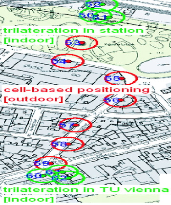
The most straightforward technology in RFID positioning is Cell of Origin (CoO) where the location of the reader is described by a cell identified by the maximum read range to a tag. However, this method is only well suited for applications where accuracy is not that important. In an experiment for the path from a public transport stop (i.e., underground station ‘Karlsplatz’) to the University building cell-based positioning has been applied in outdoor areas as an alternative to GPS positioning (see Figure 1). Three RFID tags were installed at the entrance of the underground station ‘Karlsplatz’ (indoor area). Along the way between the underground station and the university building (‘TU Vienna’ in Figure 1; outdoor area) seven tags were installed. Additionally, three tags were installed at the building's entrance (indoor area). Each circle indicates a different cell. Ranges from the RFID tags location have been achieved up to around 20 m. As the accuracy of cell-based positioning generally depends on the size of the distinguishable cells, the achievable positioning accuracies are not sufficient for indoor areas. Therefore several RFID tags have been installed in the transition zones between outdoor and indoor to be able to locate the user with a higher precision using trilateration.
An example of a cell-based positioning concept in outdoor areas of the city of Vienna in conjunction with the trilateration concept for indoor areas.

Apart from the tag's ID and the information stored on the tag, the signal strength of the signal between the tag and the reader can also be determined when reading the tag. This additional information can be used for position determination. If the signal strength is converted to a range to the tag and several tags are located in the surrounding environment, the readers' location can be obtained using trilateration. On the other hand, the signal strength can be used directly for RFID location fingerprinting if the signal strength has been determined at known locations previously in the test area. Both methods have been investigated in our project and are now described.
Trilateration
Trilateration is the second method of determining the relative positions of moving objects (e.g. a user with a portable RFID reader) using the known location of two or more tags in the surrounding environment, and the range between them. Geometrically at least two ranges are necessary for 2-D and three ranges for 3-D position determination of the RFID reader. Apart from the unknown coordinates of the reader an additional unknown has to be introduced, i.e., an unknown scale factor which takes account of the difference between the deduced ranges to the RFID tags and the reference point system. If more than the minimum number of ranges are available, the position fix can be calculated using a least squares adjustment.
The available ranges could be deduced from the RSSI. It can be assumed that the RSSI depends on the range between the RFID reader and the tag. For the conversion of the signal strength measurement different models can be employed. These will be discussed in the following subsections.
Modified ITU-R Model
One usable model is the ITU Indoor Location Model (Wikipedia, 2008) that estimates the path loss inside a room or a closed area inside a building divided by walls of any form. It assumes a logarithmic relationship between the measured RSSI and the range from the transmitter. Mathematically the ITU-R model (Ranvier, Reference Ranvier2004) can be described by:

where: s T is the total signal strength in [dBm], f c is the carrier frequency in [MHz], n is the signal strength exponent, r is the range between the RFID tag and the RFID reader in [m] and s f(n f) is the floor penetration factor of the signal strength which depends on the number of floors between the RFID tag and RFID reader in the building.
In the case of RFID the parameters used are different to those in Equation (1). In order to find out the suitable parameters for a RFID system, a new simplified equation using three fixed parameters as shown above is developed as follows:

where: c 0=20⋅log10f c+s f(n f)−28 and c 1=10⋅n with c 0 as the unknown coefficient that includes the fixed carrier frequency and the number of floors in the building and where c 1 is the range power loss coefficient.
The unknown coefficients c 0 and c 1 can be determined using a calibration on a known baseline inside the building. Then the range r between the RFID tag and the RFID reader can be brought from the right hand side to the left hand side of Equation (2). Therefore the range r can be determined as follows:
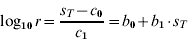
with the coefficients  and
 .
Polynomial Model
A polynomial model describes a polynomial relationship between independent and dependent variables. Linear regression produces a polynomial model that is linear in the coefficients. In such a polynomial model it is assumed that the RSSI decreases linearly with range. A further improvement of the accuracy of the approximation can be achieved if the right hand side in Equation (3) is extended by a polynomial function of order m as described in the following equation:

where: r is the range to the RFID tag in [m], s T is the measured signal strength in [dBm], b m are the unknown coefficients of the polynomial function and m is the order of the polynomial function.
In tests reported in Retscher and Fu (Reference Retscher and Fu2007b) it could be seen that a polynomial relationship s T vs. r provides better results than a polynomial relationship s T vs. log10r. For this reason, the log10r in Equation (4) can be substituted by r as described in the following equation:

where: a m are the unknown coefficients of the polynomial function and m is the order of the polynomial function.
MATLAB has a command for polynomial curve fitting fit a to calculate the unknown coefficients a m if the signal strength s T is measured along a baseline at n known regular ranges:

Then there are n equations with m+1 unknowns (where n must be >m+1). The order m of the polynomial function depends on the number of available signal strength observations n and the desired level of approximation. Further tests of the different models have shown that a polynomial model gives very similar results to a more complex logarithmic model (see Retscher and Fu, Reference Retscher and Fu2007a). Because of simplicity therefore a polynomial will be used.
Calibration for the Signal Strength to Range Conversion
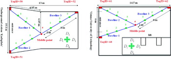
In order to get the coefficients of the polynomial model a calibration was carried out in two indoor environments. Figure 2 shows the installation of the tags in the indoor area, i.e., the entrance of the underground station ‘Karlsplatz’ and the entrance to the office building (‘TU Vienna’). For the conversion of the signal strength into a range, a calibration along three baselines from the RFID tags has been performed to obtain calibration parameters of a characteristic curve for each line. For that purpose the signal's strength has been measured at 2 m intervals in four different directions D 1, D 2, D 3, and D 4 according to the surrounding environment. A calibration at 2 m intervals was chosen because it is assumed that the signal strength decreases linearly with range with a mean error range of 2 to 3 m. A calibration in four different directions is required as the signal strength depends on the antenna direction with respect to the tag's location. It must be noted that the resulting characteristic curves are only valid for the chosen environment. After the calibration, the calibration parameters according to environment are stored in a database. Then the measured RSSI to a certain tag can be converted into a range to the corresponding tag using the knowledge of the calibration. In this paper, we choose calibration parameters that optimize the RFID system, instead of the calibration parameters according to environment. Test results in the described environments will be presented in Section 3.1.
Location of the RFID tags at the entrance of the underground station ‘Karlsplatz’ (Left) and the university building (Right) used for trilateration.

RFID Location Fingerprinting
The accuracy of the trilateration depends mainly on the accuracy of the measured range. The achievable positioning accuracies might not be sufficient for small confined indoor areas (e.g. location along the corridor at the centre of the building). In order to create a more generally applicable localization method than using trilateration, the RFID location fingerprinting is used for positioning to provide more accurate location estimates. The principle of operation of RFID fingerprinting is similar to that used in WiFi networks (see e.g. Retscher et al., Reference Retscher, Moser, Vredeveld, Heberling and Pamp2007; Kaemarungsi, Reference Kaemarungsi2005). Generally, the location fingerprinting could be divided into two phases: an off-line or training phase and an on-line or positioning phase. This is discussed in more detail in the following subsections.
Off-line Phase
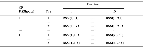
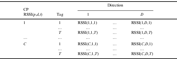
In the off-line phase a database of signal strength values to the surrounding RFID tags at known locations is created. The location fingerprints are collected by performing a site-survey of the received signal strength indication (RSSI) from multiple RFID tags at every location for four different directions of the RFID reader antenna. The RSSI values at a particular location to a certain tag in a particular direction are stored in a database in the form of means of the total scans. The accuracy of the position measurement can be improved by increasing the number of scans and by increasing the number of points in the database. Therefore the database can be created with not only calibration points but also with interpolation points. Table 1 shows the database with the calibration points (CP) which have values RSSI(p,d,t) of C calibration points in D directions to T tags in the off-line phase assigned; where p is the total number of points running from 1 to C, d is the total number of directions running from 1 to D and t is the total number of tags running from 1 to T. The rows in the table describe the measured RSSI for each tag from every calibration point CP. Usually the number of directions D is four in the calibration.
The database with RSSI(p,d,t) of C calibration points CP in D directions to T tags in the off-line phase.
For densification of the points in the database, a database with interpolation points can be created by using different interpolation methods between the calibration points, e.g. two-point interpolation and four-point interpolation. The purpose of the interpolation is to increase the number of points in the database without additional measurements so that the accuracy of position measurement can be improved. Then the database also includes a new RSSI value at IP2 in the middle between two calibration points CP1 and CP2 in the case of two-point interpolation or a new RSSI value at IP4 in the middle of four calibration points CP1, CP2, CP3, and CP4 in the case of four-point interpolation (see Fu, Reference Fu2008).
On-line Phase
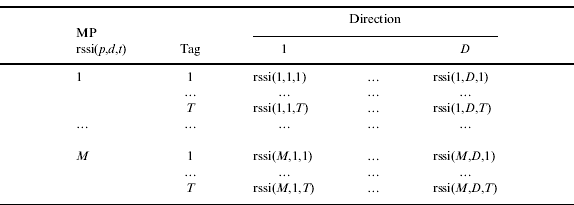
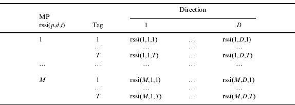
The second phase is the on-line phase which is also called positioning phase. In this phase a RFID reader will report a measurement of rssi from different RFID tags at a certain location where the reader should be positioned. To estimate the location an algorithm named “nearest neighbour in signal space” (NNSS) can be employed. In this algorithm the Euclidean distance between the measurement of the rssi(p,d,t) and each fingerprint in the database RSSI(p,d,t) is computed in signal strength space. Table 2 shows the rssi(p,d,t) of the measured points in D directions to T tags (e.g. four tags) in the on-line phase. The rows in the table describe the measured rssi(p,d,t) for each tag from every measurement point MP.
The rssi(p,d,t) of M measurement points MP in D directions to T tags in the on-line phase.
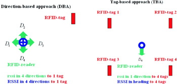
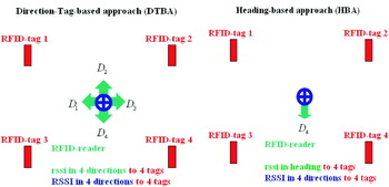
Four different approaches can be distinguished to assign the measured rssi to the location in the on-line phase, namely, the direction-based approach (DBA), the tag-based approach (TBA), the direction-tag-based approach (DTBA) and the heading-based approach (HBA). In the experiment, DBA and DTBA use measurements in four directions and TBA and HBA use measurements in heading (one direction). The main principles of the four approaches are:
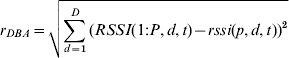
• Direction-based Approach. The DBA can be used to estimate the location of the RFID reader with measurements in four directions to one tag. DBA develops the NNSS algorithm using RSSI (blue circle with arrow) and rssi (green arrow) in four directions (D 1, D 2, D 3, and D 4) per tag per point (see Figure 3, Left). P is the number of the points in the database; D is the number of directions. The find function can find the point number with minimum r DBA. If there are several tags, the hisfu function can be used which is a frequency function that can count the number of occurrences of a point number (PNR) and select the point number with maximum frequency. Then the following MATLAB code is used to investigate the range r DBA between the two vectors for positioning: for t=1:T % T is number of tags.for p=1:M % M is number of measurement point.
(7)PNR(p,t)=find(r DBA==min(r DBA))endendfor p=1:M[PNR(p), frquency]=hisfu(PNR(p,1:T)′)end.
• Tag-based Approach. TBA can be used to estimate the location of the RFID reader with measurements in heading to several tags. TBA develops the NNSS algorithm using RSSI (blue circle without arrow) and rssi (green arrow) in one direction (i.e., D 4) to several tags (i.e., 4 tags) per point (see Figure 3, Right). P is the number of the points in the database; T is the number of tags. The find function can find the point number with minimum r TBA. If there are several directions, the hisfu function can be used which is a frequency function that can count the number of occurrences of a point number (PNR) and select the point number with maximum frequency. Then the following MATLAB code is used to investigate the range r TBA between the two vectors for positioning:for d=1:D % D is number of directions.for p=1:M % M is number of measurement point.
(8)PNR(p,d)=find(r TBA==min(r TBA))endendfor p=1:M[PNR(p), frequencecount]=hisfu(PNR(p,1:D)′)end.• Direction-tag-based Approach. The DTBA can be used to estimate the location of the RFID reader with measurements in four directions. DTBA develops the NNSS algorithm using RSSI (blue circle with arrow) and rssi (green arrow) in four directions (D 1, D 2, D 3, and D 4) to several tags (i.e., 4 tags) per point (see Figure 4, Left). P is the number of the points in the database; D is the number of directions; T is the number of tags. The find function can find the point number with minimum r DTBA. DTBA is a combination of DBA and TBA. The basic idea of the combination approach is to obtain the benefits of both. Then the following MATLAB code is used to investigate the range r DTBA between the two vectors for positioning: for p=1:M
(9)PNR(p)=find(r DTBA==min(r DTBA))end.• Heading-based Approach. The heading-based approach (HBA) can be used to quickly estimate the location of the RFID reader with only measurements in heading. HBA develops the NNSS algorithm using RSSI (blue circle with arrow) in four directions to several tags (i.e., 4 tags) and rssi (green arrow) in one direction (i.e., D 4) to several tags (i.e., 4 tags) per point (see Figure 4, Right). P is the number of the points in the database; D is the number of directions; T is the number of tags; h is the heading. The find function can find the point number with minimum r HBA. HBA is a combination of TBA and DTBA. The basic idea of the combination approach is to obtain the benefits of both. HBA has the advantage compared to DTBA that the RFID location fingerprinting runs faster, but with the drawback that HBA is less accurate. Then the following MATLAB code is used to investigate the range r HBA between the two vectors for positioning:for p=1:M
(10)PNR(p)=find(r HBA==min(r HBA))end.



Left: Direction-based approach (DBA). Right: Tag-based approach (TBA).

Left: Direction-Tag-based approach (DTBA) Right: Heading-based approach (HBA).

Table 3 shows an overview of these four approaches for the on-line phase of RFID location fingerprinting. The methods differ from each other in their approaches, in run time and their achievable accuracies. DBA and TBA are basic approaches and DTBA and HBA are the more advanced approaches. DTBA is a combination of DBA and TBA to obtain the benefits of both. Then high accurate point positioning can be achieved, however, with the trade-off of a slow run time. It also requires the measurement in four directions at every point. For this reason, HBA was developed based on TBA and DTBA to achieve middle to high accuracy with a fast run time. Test results will be shown in Section 3.2.
An overview of the four approaches for the on-line phase of RFID location fingerprinting.

TEST EXPERIMENTS AND THEIR RESULTS
In this section test experiments for active RFID positioning at the Vienna University of Technology and its surroundings are described. The tests using trilateration are discussed in Section 3.1 and the experiments using location fingerprinting in Section 3.2.
Trilateration Experiments
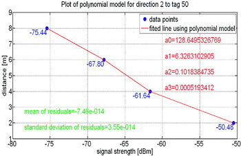
For trilateration first of all a calibration along baselines has to be performed. The goal of the calibration is to obtain the coefficients of the polynomial model for the signal strength to range conversion. The calibration was performed as described in Section 2.2.3. After the measurements the coefficients of the polynomial model for every used tag were computed according to Equations (5) and (6). In this paper, we choose coefficients that optimize the RFID system, instead of the coefficients according to the environment. For this reason, the calibration was performed in the entrance of the underground station ‘Karlsplatz’ (compare Figure 2, Left). Figure 5 shows the coefficients of a polynomial model with an order of m=3 for one baseline in direction 2 to tag 50. The mean value of the residuals is nearly zero (i.e., only −7·46∗10−14 m) and the standard deviation is only ±3·55∗10−14 m using the polynomial model.
Coefficients of a polynomial model for a baseline in the entrance of the underground station ‘Karlsplatz’.

Now the polynomial model for the used tags is known with its coefficients. In the positioning phase the reader will receive signals with IDs from at least two tags. Then the range between the reader and tags can be computed with the corresponding polynomial model. The coordinates of the reader in 2-D can then be obtained using trilateration. In the following the results of the trilateration experiments will be discussed.
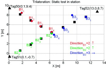
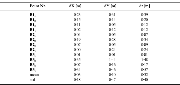
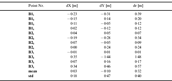
Two types of test were carried out. In the first test the signal strength measurements were performed static over a time span of around one minute at the same locations used in the calibration, since we knew the true location of these points. In the second test the user was walking continuously inside the test area either from the entrance to the centre of the test area or vice versa. The positioning results of the static test in the entrance of the underground station ‘Karlsplatz’ are shown in Figure 6. Table 4 shows the deviations in the X- and Y-coordinates (dX and dY) from their true location and the radial deviation dr for all test points. On average the radial deviation is only 0·32 m with a standard deviation of ±0·40 m. The maximum deviation of one point was 0·34 m in the X-coordinates and −1·44 m in the Y-coordinates. This point can be considered as an outlier as the deviations of the other points are much smaller (see Table 4). Similar results were achieved for the entrance of the university building of the Vienna University of Technology (compare Figure 2, Right). The average radial deviation was only 0·29 m with a standard deviation of ±0·44 m.
Results of trilateration for the static test points in the entrance of the underground station ‘Karlsplatz’.

Deviations in the X- and Y-coordinates (dX and dY) from their true location and the radial deviation dr of the static test points in the entrance of the underground station ‘Karlsplatz’.
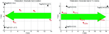
In the second kinematic test the reader was carried from the middle point on the right side of the entrance of the underground station ‘Karlsplatz’ to the middle of tag 50 and 51 (from right to left in Figure 7, Left) over a distance of around 14 m. In the entrance of the university building (‘TU Vienna’) the reader was carried from the middle of tag 60 and 61 at the building entrance to the middle point at the right end of the hallway (see Figure 7, Right) over a similar distance of around 14 m. Unlike the measurements in the first test, in this test every point was measured for only a few seconds. It can be seen from Figure 7 that the trend of the trajectories could be correctly determined. The positioning accuracy was in the range of ±2 to 3 m.
Results of trilateration for the kinematic test in the entrance of the underground station ‘Karlsplatz’ (Left) and in the entrance of the university building (‘TU Vienna’) (Right). (The determined location is shown in seconds s from the start of the measurements).

Location Fingerprinting Experiments
Test Environment Setup and Configuration Issues
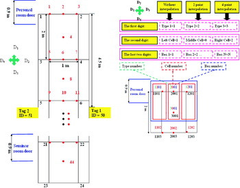
Measurements for the experiment were carried out along the corridor on the 3rd floor inside the building of the Vienna University of Technology on Gusshausstrasse 27–29, Vienna, Austria. The total length of the selected part of the corridor is 24 m (see Figure 8, Left). The distance from the entrance to the corridor to tag 1 and 2 is 4·5 m. The distance between the tags along the corridor is 12 m and the width of the corridor is 2·0 m. The distance from tag 3 and 4 to the end of the selected part is 7·5 m. Four tags have been mounted at 1·5 m above the floor on the wall.
Left: Test environment for location fingerprinting. Right: The numeration scheme for measurement along the corridor.

In the offline phase, measurements on 24 points (black numbers in Figure 8, Left) were carried out and in the online phase 44 points (red numbers in Figure 8, Left) were measured. The measurements per point were carried out in either one or four directions depending on the employed approach, i.e., DTBA or HBA (compare Section 2.3.2). In order to position all of the points (especially the points in the middle of the corridor) during the online phase with an acceptable accuracy, the RSSI values in the middle of the corridor have to be interpolated by two-point interpolation or four-point interpolation (Compare Section 2.3.1) using the measurements in the offline phase.
Figure 8, Right illustrates the numbering scheme of the calibration and measurement points. To obtain a better overview of the data and to distinguish the point with or without interpolation, as well as the point on the left, in the middle or on the right side of the corridor, and to describe the point in front of the personal room door or the seminar room door, these points were assigned new numbers. The new numbers consist of four digits:
• The first digit denotes the type of the interpolation, in which digit 1 represents no interpolation, digit 2 represents two-point interpolation and digit 3 represents four-point interpolation.
• The second digit assigns the cell in which the point lies. Digit 1 means that the point lies in the left cell, digit 2 means that the point lies in the right cell and digit 0 means that the point lies in the middle cell.
• The last two digits are the box number. Here digit 1 means the point is near the personal room at the entry to the corridor, digit 11 means the point is near the seminar room (compare Figure 8, Left). A decreasing box number means a movement direction towards the personal room, while an increasing digit means a movement direction towards to the seminar room.
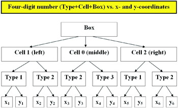
Figure 9 shows the tree structure of the numeration scheme and indicates the advantages of a four-digit number compared with the use of x- and y-coordinates: (i) the four-digit number is one dimensional, while the x- and y-coordinates are two dimensional; (ii) the number also includes the information of the location of the point; (iii) the number shows whether the RSSI values of a point have been obtained by interpolation or not in the offline phase; (iv) the number indicates the direction of movement in positioning. These advantages are very useful for the analysis of the results of the experiments.
Tree structure of the numeration scheme.

Result of Experiments Using DTBA
In the experiments using DTBA either tests without interpolated points (see Figure 10, Left) or with interpolated points (see Figure 10, Right) in the database were carried out.
Left: The results of the experiment using DTBA without interpolation. Right: The results of the experiment using DTBA with interpolation.

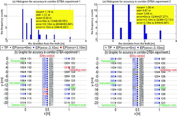
In the tests where no interpolated points were used it could be seen that the accuracy of the position was lower. The histograms at the top of Figure 10 shows that the deviations from the truth distribute with a mean value of 1·19 m and standard deviation of 1·31 m and a maximum value of 6·02 m. About 29·55 percent (13 out of 44 points) of the measured points in the online phase could be positioned correctly, while about 63·64 percent (28 out of 44 points) of the measured points were positioned with an accuracy of better than 3·10 m. Only three points (less than 6·82 percent) were positioned with a deviation from the truth larger than 3·10 m. The graphic in the lower part of Figure 10 shows the distribution of the measured points along the corridor. The number of the estimated point (EP) is shown on the left side of the point, while the number of the true point (TP) is on the right side. The graphic shows that the points in the middle of the corridor have been positioned with lower accuracies than those along the wall. One reason might be that for the points in the middle of the corridor no direct observations in the off-line phase were made. The deviation of the assigned point on point 1203 was larger than 3·10 m, because this point is located near the technology room door where a lot of metal is present which can affect the signal strength measurements.
Figure 10, Right shows the results of the test using interpolated points. Comparing the histogram and the graphic in Figure 10, Right with those in Figure 10, Left it can be seen that the positioning accuracies using DTBA with interpolated points are clearly better than those without interpolation. Better results are also obtained for the points in the middle of the corridor as the database now contains points determined with two-point or four-point interpolation. The deviation from the truth is on average 1·00 m (0·19 m better than that without interpolation) and all of the points were positioned with a maximum deviation less than 3·10 m.
Result of Experiments Using HBA
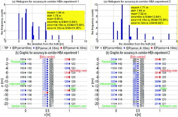
Similar to the experiments using DTBA the tests using HBA have been carried out using databases with and without interpolated points (see Figure 11). The measurements using HBA are less time-consuming than the experiments using DTBA, because HBA needs only one measurement at the measured point in one direction. The results of HBA without interpolation are summarized in Figure 11, Left. The histogram in upper Figure 11, Left shows that the average deviation from the truth in the experiment using HBA is 1·94 m, which is almost double that in the test using DTBA. From the graphic in Figure 11, Left it can be seen that using HBA positioning accuracy of 4·10 m can be achieved. In comparison Figure 11, Right shows the positioning accuracies that can be achieved if interpolated points are used in the database. The results with interpolation indicate that the deviation from the truth is on average 1·71 m (0·23 m better than that without interpolation).
Left: The results of the experiment using HBA without interpolation. Right: The results of the experiment using HBA with interpolation.

DISCUSSION OF TEST RESULTS FOR ACTIVE RFID POSITIONING
The positioning accuracy if cell-based positioning (CoO) is used depends on the size of the distinguishable cells. In our case we have achieved ranges from the RFID tags location up to around 20 m. Cell-based positioning cannot be used in indoor environments due to its low positioning accuracy, but the achievable accuracy can be sufficient enough for positioning in outdoor environments near underground stations or public buildings, because the user is usually following the street or road network and can sometimes use landmarks for orientation. So CoO can be employed to replace GNSS positioning in outdoor environments if GNSS is not available.
For trilateration a conversion of the measured RSSI into ranges has to be performed using a conversion model. For the conversion from the signal strength to a distance, the regression is without bias as the resulting mean value of the residuals is nearly zero (i.e., only −7·46∗10−14 m) and the standard deviation is only ±3·55∗10−14 m using the polynomial model with an order of m=3. The polynomial model is easier to handle and usually provides similar results to a logarithmic relationship between the signal strength and the range (see Retscher and Fu, Reference Retscher and Fu2007a). The polynomial models were then used for the deduction of ranges to the tags for the location of points in static and kinematic tests. In the static test the test points were located with accuracies of better than ±0·34 m in X-direction and ±1·44 m in Y-direction. In the kinematic tests lower accuracies in the range of ±2 to 3 m were achieved, but the trend of the moving user was always determined correctly. The positioning accuracies achieved have proved that RFID trilateration can be successfully employed at small ranges to tags in indoor environments where at least three tags are installed (e.g. at building entrances and entrances to public transport stops).
In location fingerprinting a positioning accuracy below one metre could be achieved. The average accuracy of the experiments using DTBA was around 80 cm better than that of the experiments using HBA. But the observation time of DTBA is much longer than that for HBA as DTBA requires signal strength observations in four directions. Another advantage of HBA is that the user's orientation could be determined in addition to the location. Furthermore, the use of a database that also includes interpolated points apart from the measured calibration points leads to an improvement of the result of more than 20 cm in positioning accuracy compared to the database using only the calibration points.
CONCLUSIONS AND OUTLOOK
The paper addresses the use of long-range active RFID for positioning in indoor environments. Two methods have been investigated; trilateration, using ranges to the surrounding RFID tags deduced from received signal strength measurements, and RFID location fingerprinting. For the signal strength to distance conversion for trilateration different models have been deduced and tested. It could be seen that a polynomial model performs best for the conversion of the signal strength to ranges to the surrounding RFID tags. Then positioning accuracies at the level of one-to-a-few metres can be achieved for static and kinematic point positioning. In the future, we will perform more experiments to improve the polynomial model for signal strength to distance conversion. At the same time the algorithms will be tested in larger and more complicated environments and with more tags.
For location fingerprinting different advanced approaches have been developed, i.e., a direction-based approach (DBA), a tag-based approach (TBA), a direction-tag-based approach (DTBA) and a heading-based approach (HBA). For the creation of the database in RFID location fingerprinting, interpolation methods have been introduced in order to achieve a further improvement of the positioning accuracy. Experiments were carried out to test these advanced approaches. The test results showed that a positioning accuracy at best of about one metre could be achieved. In the future we are going to use linear interpolation instead of two-point interpolation for the densification of the database. Four-point interpolation will also be replaced by cubic interpolation. Furthermore we plan to carry out measurements in more complex environments. Finally, the method of HBA should be further improved.
ACKNOWLEDGEMENTS
The research work presented in this paper is fully supported by the FWF Project “Ubiquitous Carthograpy for Pedestrian Navigation UCPNAVI” (Project No. P19210-N15) of the Austrian Science Fund (FWF Fonds zur Förderung wissenschaftlicher Forschung).
The authors would like to take this opportunity to thank the students who participated in the LBS practical course 2007/08 for their assistance in the performance of the test measurements with the RFID system.