I. INTRODUCTION
Negative index metamaterials (NIMs) are in general artificial metal/dielectric composite structures exhibiting simultaneously a negative permittivity ε and permeability μ over a common frequency range [Reference Veselago1]. Following the work of Pendry et al. on negative permeability from split ring resonators (SRRs) [Reference Pendry, Holden, Robbins and Stewart2] and negative permittivity from an array of thin wires [Reference Pendry, Holden, Stewart and Youngs3], the first demonstration of an NIM has been done by Smith et al. [Reference Smith, Padilla, Vier, Nemat-Nasser and Schultz4] in 2000. Since then, metamaterials have attracted considerable interests [Reference Shelby, Smith and Schultz5–Reference Zhang, Fan, Minhas, Frauenglass, Malloy and Brueck9] because of their unusual electromagnetic properties and because of their potential applications such as invisibility cloaks [Reference Leonhardt10–Reference Kanté, de Lustrac, Lourtioz and Burokur14], perfect lenses [Reference Pendry15], and directive antennas [Reference Burokur, Latrach and Toutain16–Reference Tichit, Burokur and de Lustrac18]. Great efforts are actually done to simplify metamaterials design. Due to the saturation of the magnetic response of SRRs at optical frequencies [Reference Zhou, Koschny, Kafesaki, Economou, Pendry and Soukoulis19], a different topology composed of metal wire pairs with dielectric spacing has been introduced theoretically by Podolskiy et al. to exhibit a negative refractive index n [Reference Podolskiy, Sarychev and Shalaev20]. Later, pairs of symmetric finite-length wires (cut wire pairs) [Reference Shalaev21] have been shown to be not only able to replace conventional SRRs to produce a negative magnetic permeability μ under normal to plane incidence, but also to lead to a negative refractive index n in the optical regime. However in a recent review paper [Reference Shalaev22], Shalaev stated that it is very difficult to achieve a negative refractive index with exclusively symmetric wire pairs and that the negative index value observed in ref. [Reference Shalaev21] was accomplished in part because of the significant contribution from the imaginary part of μ. However, other related works on cut wire and plate pairs have not shown a negative index [Reference Dolling, Enkrich, Wegener, Zhou, Soukoulis and Linden23]. Instead, Zhou et al. emphasized that the condition to obtain simultaneously negative permittivity and permeability by pairs of finite metallic wires is very restrictive [Reference Zhou, Zhang, Tuttle, Koschny and Soukoulis24] and showed the possibility of obtaining a negative refractive index by combining periodic continuous and cut wires in the microwave regime. Zhou et al. also theoretically proposed a left-handed material using only symmetric cut wire pairs by increasing the equivalent capacitance between two consecutive short wire pairs so as to adjust the electric resonance frequency [Reference Zhou, Economou, Koschny and Soukoulis25]. This increase of capacitance can only be obtained by strongly reducing the spacing between two consecutive wire pairs, which will be limited according to the fabrication technology especially when we tend to high frequencies.
In this paper, we investigate numerically and experimentally the electromagnetic properties of recently proposed asymmetric cut wire pairs metamaterials [Reference Sellier, Burokur, Kanté and de Lustrac26] to achieve a negative index. An analogy is made between the presented asymmetric cut wire pairs and previously reported S-shaped metamaterials by Chen et al. [Reference Chen27]. Similar electromagnetic behavior found between the two structures is explained by a simple unification approach. The asymmetric cut wire structure constitutes a good alternative to conventional SRR-based NIMs since it works under normal-to-plane incidence. Moreover, it presents fewer metallic parts than the cut-continuous wires structure of ref. [Reference Zhou, Zhang, Tuttle, Koschny and Soukoulis24] and the fishnet structure of ref. [Reference Kafesaki, Tsiapa, Katsarakis, Koschny, Soukoulis and Economou28], ensuring low losses. Numerical simulations performed using the finite element method (FEM)-based software HFSS [29] are run to show and understand the electromagnetic behavior of the asymmetric cut wire pairs design. A single layer of the metamaterial is characterized by reflection and transmission measurements. The retrieved parameters show simultaneous resonances in the permittivity and permeability responses leading to a negative index of refraction. The results are confirmed by experimental measurements. A prism made of this metamaterial is engineered and used not only to observe a negative refraction, but also to estimate and verify the refractive index.
II. S-SHAPED METAMATERIAL
The symmetric cut wire pair structure has shown only negative μ in [Reference Dolling, Enkrich, Wegener, Zhou, Soukoulis and Linden23–Reference Zhou, Economou, Koschny and Soukoulis25]. It can be viewed as a simplification of a single-ring resonator with several cuts, a modified version of Pendry's double-ring resonator, which has been proved capable of exhibiting negative μ in [Reference Zhou, Koschny, Kafesaki, Economou, Pendry and Soukoulis19]. For this particular reason, we propose to study firstly a resonator which is able to exhibit simultaneously negative ε and μ and therefore a negative index. A promising candidate seems to be the S-shaped resonator. A doubled-sided version has been studied by Chen et al. in [Reference Chen27], where a clear negative index band has been shown.
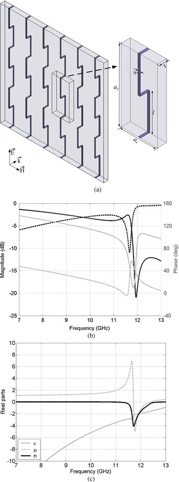
The basic structure of a periodic array of single-sided S-shaped resonators together with a unit cell is shown in Fig. 1(a). The substrate used is an epoxy dielectric board of thickness t = 1.2 mm and of relative permittivity ε r = 3.9. For the sample reported here to operate in the microwave regime, the width of the wires denoted by w is 0.3 mm. The length of the wires is l = 9.5 mm and the unit cell size in the x and y direction is respectively a x = 4.75 mm and a y = 19 mm. We shall note that the structure can be easily designed without the use of the dielectric board. However, the dielectric board is present in the actual simulation to simplify the unification process which will be described in the next section. The reflection and transmission spectra of the metamaterial are calculated using HFSS by applying the necessary electric and magnetic periodic boundary conditions on the unit cell. Figure 1(b) shows the calculated S-parameters of the metamaterial for a single layer configuration. At 11.67 GHz, a peak and a dip is, respectively, observed in the magnitude of S 11 and S 21. For the phase characteristics, a dip and a peak appears respectively for S 11 and S 21 at this same frequency. We can note that a change in sign occurs for the transmission phase at this resonance dip.
(a) Schematic representing the S-shaped metamaterial unit cell. (b) Computed reflection and transmission coefficients for symmetrical cut wire pairs materials. (c) Computed effective parameters ε, μ, and n.

Using the retrieval procedure described in [Reference Nicolson and Ross30, Reference Smith, Schultz, Markos and Soukoulis31], based on the inversion of the reflection and transmission coefficients, the effective parameters of the bi-layered metamaterial structure are extracted. The metamaterial has a period very small compared to the wavelength λ (less than λ/20) in the propagation direction. The propagation of the electromagnetic wave traveling along this direction is therefore dominated by this deep sub-wavelength period and not by the in-plane period a x or a y, justifying the description of the S-shaped metamaterial with an effective index [Reference Valentine32].
The extracted permittivity ε, permeability μ, and refractive index n are shown in the various parts of Fig. 1(c). As illustrated by the extracted parameters from the calculated S-parameters, the S-shaped metamaterial structure exhibits firstly a Drude model-like permittivity response with negative values in the 7–13 GHz frequency band considered, due to electrical connection between consecutive S cells. Similar permittivity response can be observed in arrays of thin wires [Reference Pendry, Holden, Stewart and Youngs3]. Secondly, a magnetic resonance appears on the right-hand side of the resonance dip at 11.67 GHz. As for Pendry's double-ring resonator (SRR) [Reference Pendry, Holden, Robbins and Stewart2], the negative permeability is obtained by exciting resonant circular currents in the C-shaped half parts of the S in order to create the strong magnetic resonance. The extracted real part of the refractive index is therefore negative around 11.67 GHz.
III. UNIFICATION APPROACH AND ASYMMETRIC CUT WIRE PAIRS METAMATERIAL
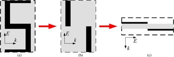
By continuous transformation, the basic structure of the S-shaped resonator shown in Fig. 2(a) can be reduced to a pair of asymmetric metal bars separated by a dielectric spacer of thickness t [Reference Sellier, Burokur, Kanté and de Lustrac26]. In Figures 2(b) and 2(c) the view in the (E, k) plane of this structure is shown. The design shown in Figs. 2(b) and 2(c), besides its simplicity, has distinct advantages over conventional SRR-based NIMs and S-shaped resonators. The incident electromagnetic wave is normal to the structure enabling to build NIMs with a single layer of sample. Conventional SRRs, although they exhibit magnetic resonance that may produce negative μ, fail to give negative ε at the same frequency range, and hence by themselves they are incapable of producing NIMs. An extra continuous wire is needed to obtain negative ε via a plasmonic response [Reference Pendry, Holden, Stewart and Youngs3, Reference Smith, Padilla, Vier, Nemat-Nasser and Schultz4]. In contrast, the pair of asymmetric parallel wires in Fig. 2(c) is expected to exhibit not only a magnetic resonance (antisymmetric mode) but an electric resonance as well (symmetric mode) properly located in frequency to have overlapping of μ and ε [Reference Burokur, Sellier, Kanté and de Lustrac33].
The S-shaped resonator: (a) can be transformed to a pair of asymmetric parallel metallic bars separated by a dielectric; (b) and (c) view in (E, k) plane.

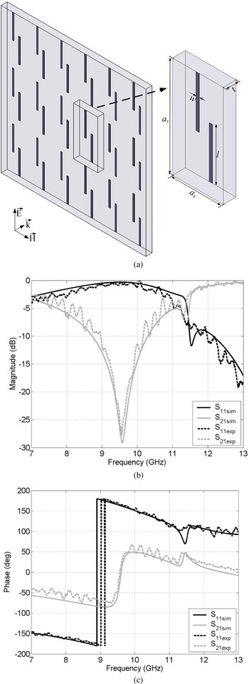
A single unit cell of our cut wire pairs metamaterial is shown in Fig. 3(a). It consists of a bi-layered structure composed of periodic cut wires of finite length. Compared to the cut wires structure of refs. [Reference Podolskiy, Sarychev and Shalaev20–Reference Zhou, Economou, Koschny and Soukoulis25], the finite wires in our case do not face each other on the dielectric board. In fact, the wires on one face are laterally shifted along the y-axis by the length l. The structure is printed on both faces of the epoxy dielectric board of thickness t = 1.2 mm and of relative permittivity ε r = 3.9. For the different samples reported here, the width of the cut wires denoted by w is 0.3 mm. The length of the cut wires is l = 9.5 mm and the unit cell size in the x and y direction is, respectively, a x = 9.5 mm and a y = 19 mm. These dimensions optimized to operate around 10 GHz are the same as for the S-shaped resonator in Section II, except for a x. A smaller a x is needed for the S-shaped resonator to produce a plasma frequency (ε = 0) of the Drude model-like permittivity response above the magnetic resonance so as to overlap negative values of ε and μ. To examine the performances of cut wire pairs, the properties of the structure of Fig. 3(a) are characterized numerically using FEM simulations done with HFSS. For an electromagnetic wave incident with a wave vector and field polarization of Fig. 3(a), cut wire pairs will exhibit a magnetic resonance at the frequency f m as well as an electric resonance at the frequency f e. Several samples of the structure consisting of 10 × 5 cells on a 120 mm × 120 mm epoxy substrate are fabricated using conventional commercial chemical etching technique. Measurements are done in an anechoic chamber using an Agilent 8722ES network analyzer and two X-band horn antennas. In the transmission measurements, the plane waves are incident normal to the prototype surface and a calibration to the transmission in free space (the metamaterial sample is removed) between the two horn antennas is done. The reflection measurements are done by placing the emitting and receiving horn antennas on the same side of the prototype and inclined with an angle of about 5° with respect to the normal on the prototype surface. The calibration for the reflection is done using a sheet of copper as reflecting mirror.
(a) The asymmetric cut wire pairs structure under normal-to-plane propagation (a x = 9.5 mm, a y = 19 mm, w = 0.3 mm, l = 9.5 mm). The insets show the direction and the polarization of the wave. (b)–(c) Computed reflection and transmission coefficients for symmetrical cut wire pairs materials.

Figures 3(b) and 3(c) show the calculated (continuous lines) and measured (dashed lines) S-parameters of the metamaterial for a single layer configuration. There is a very good qualitative agreement between simulations and measurements. The calculated and measured magnitudes of S 21 presented in Fig. 3(b) show clearly two resonance dips, the first one at 9.58 GHz and a second one at 11.39 GHz. Similar to the S-shaped resonator, a change in sign occurs for the transmission phase at the first resonance dip. At the second resonance dip, a peak and a dip is, respectively, observed in the transmission and reflection phase response.
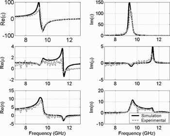
The extracted permittivity ε, permeability μ, and refractive index n are shown in the various parts of Fig. 4. Two extraction procedures have been performed: the first one uses the calculated S-parameters and the second one is based on the measured S-parameters. It must be noted that the extraction from the measured spectra are presented without any fitting. As illustrated by the extracted parameters from the calculated and measured S-parameters, the cut wires structure shows firstly an electric resonance at the first resonance dip observed at 9.58 GHz in Fig. 3(b). This electric resonance exhibits values going negative for the real part of the permittivity in the vicinity of the resonance. To compare with the S-shaped metamaterial, the cut wire pairs present a strong resonance instead of a Drude model-like permittivity response since it exists no electrical contact between consecutive wires. Secondly, a magnetic resonance with negative values appears at the right-hand side of the second resonance dip at 11.5 GHz. In essence, the cut wire pair is a “two-gap” SRR that has been flattened [Reference Dolling, Enkrich, Wegener, Zhou, Soukoulis and Linden23]. For an electromagnetic wave incident with wave vector and field polarization as shown in Fig. 3(a), the asymmetric cut wire pair will exhibit both inductive and capacitive behavior and will possess magnetic resonance providing a negative permeability. Around the same frequency, the real part of the permittivity is still negative. The extracted real part of the refractive index is therefore negative around 11.5 GHz, which is the frequency of the LH peak. However, we can also notice that the zero value for the ε response is very close to 13 GHz where a full transmission band is observed in Fig. 3(b). This frequency constitutes the frequency of the RH transmission peak. We can therefore deduce that this RH transmission peak is due to an impedance matching between the structure and vacuum.
Extracted electromagnetic properties of the asymmetric cut wire pairs metamaterial using the simulated and experimental data of Fig. 3: real parts (left column) and imaginary parts (right column) of the permittivity ε, of the permeability μ, and the refraction index n.

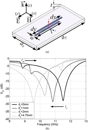
Compared to the symmetric configuration presented in [Reference Dolling, Enkrich, Wegener, Zhou, Soukoulis and Linden23–Reference Zhou, Economou, Koschny and Soukoulis25], the asymmetric one provides a frequency band where both ε and μ are simultaneously negative. In [Reference Burokur, Sellier, Kanté and de Lustrac33], the asymmetric cut wire pairs have been presented as a result of symmetry breaking of the symmetric configuration along the E-field direction as shown in Fig. 5(a). With the cut wire pairs acting as an LC resonator, the magnetic and electric resonance frequencies then depend on the total inductance of the parallel wires L, on the capacitance C m created between the upper and lower halves of the cut wire pairs, and on the equivalent capacitance C e created between two neighboring wire pairs. For the magnetic resonance, the upper and lower wires carry electrical charge with opposite signs and the equivalent capacitance C m is then concentrated between the overlapping section of the wires. At the electrical resonance, upper and lower wires carry electrical charge with the same sign leading to an equivalent capacitance C e between neighboring cells. Thus, C m depends strongly on wires overlapping surface on each face of the dielectric spacer. To increase the magnetic resonance frequency, one must necessarily decrease the capacitance C m. The simplest way to do so is to displace laterally the wires and hence break the symmetry of the structure such that a smaller overlapping surface of the wires is considered for the calculation of C m. However, the lateral displacement also leads to an increase in the equivalent capacitance C e between two neighbouring wire pairs since the distance between neighbouring wire pairs on two consecutive cells decreases. Therefore, the overall electrical length of the wire pair in a cell increases, resulting in a decrease of f e. Consequently, breaking the symmetry of the cut wire pairs causes a shift towards higher and lower frequencies for, respectively, the magnetic and electric resonance. The impact of breaking the symmetry of cut wires pairs on the magnetic and electric resonances is clearly shown in Fig. 5(b) by calculations performed for d y = 0, 0.5, 1, and 2 mm. A shift towards high and low frequencies can be observed for, respectively, f m and f e when d y increases. This phenomenon explains why the electric resonance is well below the magnetic one for the structure presented in Fig. 3(a) where d y = 4.75 mm.
(a) Schematic representing the symmetry breaking procedure of the symmetric one to reach our proposed asymmetric configuration. (b) Computed transmission coefficients of the cut wire pairs materials for d y = 0, 0.5, 1, and 2 mm. The arrows show the shift of f m and f e when d y increases.

IV. REFRACTION EXPERIMENT
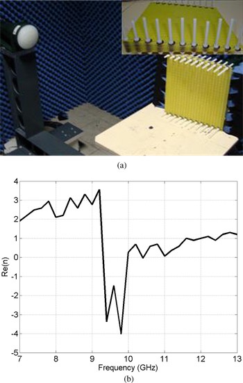
The refractive index n can also be scaled by a refraction experiment based on Snell's law where an electromagnetic wave passes through a prism made from a slab composed of 10 layers of the metamaterial under test with 1 mm air spacing between each layer [Reference Shelby, Smith and Schultz5]. The incident face of the prism is illuminated with a beam of microwaves whose electric field is polarized such that it is parallel to the wires as shown in Fig. 6(a). To determine the refractive index n, the deflection of the beam of microwave radiation as it passes through the prism-shaped metamaterial is measured. Knowing the angle of incidence α = 9.64°, the angle of refraction β is easily determined and used to calculate the index of refraction n at different frequencies by Snell's law. These values are plotted in Fig. 6(b) where a negative index can be observed around 9.7 GHz. This frequency band is different from that obtained from the extraction on one layer but is consistent with stacking multiple layers when we consider that the microwave beam passes through several layers.
(a) Experimental setup for the refraction experiment. The inset shows a side view of the fabricated prism shaped metamaterial. (b) Refractive index n obtained by the refraction experiment.

V. CONCLUSION
In conclusion, we studied the propagation of a normal-to-plane incident electromagnetic wave through an asymmetric cut wire pairs structure and we investigated numerically and experimentally its electromagnetic properties. The structure can be considered as a simplified version of previously reported S-shaped resonator by using the unifying approach. Numerical simulations have been performed in order to present the reflection and transmission spectra together with the effective parameters responses. The LH structure exhibits two transmission peaks, the first one corresponding to an electric resonance and another one corresponding to a magnetic resonance. Based on these responses, the effective parameters have been extracted to show a negative refractive index. The asymmetric structure has also been compared to a symmetric one where we have shown that the symmetry breaking procedure causes a detuning of both resonances leading to a frequency band with overlapping ε and μ. The negative index has then been verified by a refraction experiment made on an engineered prism from several layers of the metamaterial.
The results obtained from this metamaterial therefore show the possibility of obtaining a negative index from a judicious tailoring of the cut wires structures without the need for additional continuous wires as proposed in [Reference Zhou, Zhang, Tuttle, Koschny and Soukoulis24]. This reduces strongly the use of metallic parts which is quite advantageous particularly in the optical regime.
 Shah Nawaz Burokur was born in Mauritius in 1978. He received the DEA (Master) degree in microwave engineering from the University of Rennes1, France, in 2002. In 2005, he received the Ph.D. degree from the University of Nantes, France. His Ph.D. research works dealt with the applications of split ring resonators to microwave devices and antennas. From September 2005 to August 2006, he was a post-doctoral research fellow at the Laboratoire de Génie Electrique de Paris, where he worked on chiral metamaterials. For the period September 2006 to August 2009, he was a post-doctoral research fellow at the Institut d'Electronique Fondamentale (IEF) – University of Paris Sud, France. He is actually an Associate Professor at the University of Paris Ouest and carries his research activities with the Laboratoire Energétique, Mécanique, Electromagnétisme (LEME). His current research interests are in the areas of microwave and applications of periodic structures, complex media, metamaterials and metasurfaces, in the analysis of integrated planar and conformal circuits and antennas. He has published more than 20 papers in scientific journals and holds one patent on a metamaterial-based antenna. Dr. Burokur has been the recipient of the Young Scientist Award, presented by the Union Radio-Scientifique Internationale (URSI) Commission B, in 2005. He serves as reviewer of the IET Microwaves, Antennas and Propagation and Electronics Letters and also the Journal of Electromagnetic Waves and Applications.
 André de Lustrac received the Ph.D. degree in electrical engineering in the microwave domain from the Institute of Fundamental Electronics (University of Paris Sud 11) on Josephson logic devices in 1986. From 1989 to 1992 he was an assistant professor at the Institute of Technology of Cachan, France. He is currently full professor at the University of Paris 10, France. From 2002 to 2007, he was the director of the SITEC Department of the University of Paris 10. He has published more than 100 papers in journals and international conferences in the areas of the applications of the superconducting Josephson junctions in digital circuits, the simulation methods of high-frequency III–V transistors (HEMT) and quantum circuits, and last but not least, on photonic band gap materials and metamaterials in the microwave and optical domains. With his research team at the Institute of Fundamental Electronics, he explores the physics and the applications of these materials in telecoms and aeronautics. Since 2006 he is a scientific adviser of the General Direction of Research and Innovation of the French Ministry of Research and Higher Education.