I. INTRODUCTION
Equal channel angular pressing (ECAP) has been established as a scalable route for manufacturing ultrafine grained (UFG)/nanostructured metals in bulk form (comprising large cross-sections) by imposing severe plastic deformation (SPD). Reference Iwahashi, Horita, Nemoto and Langdon1,Reference Iwahashi, Wang, Horita, Nemoto and Langdon2 The process involves pressing a ram against a workpiece (billet), which sits in a channel. Due to a bend in the channel, the workpiece undergoes deformation involving high levels of strain as it advances through the bend [Fig. 1(a)]. Here, grain refinement takes place during imposition of high levels of shear strain without any significant change in the cross section geometry of the workpiece, even after several deformation passes. Reference Iwahashi, Wang, Horita, Nemoto and Langdon2 Imposition of SPD during ECAP to process fully-dense bulk forms is also facilitated by substantial hydrostatic pressure that prevails in its deformation zone. Reference Raab, Soshnikova and Valiev3,Reference Zehetbauer, Stüwe, Vorhauer, Schafler and Kohout4 Additionally, much like other plastic deformation processes, microstructure evolution here is governed by the spatio-temporal distribution of the strain, strain-rate, and temperatures in the deformation zone. Reference Abolghasem, Basu, Shekhar, Cai and Shankar5
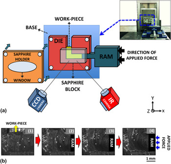
(a) ECAP die configuration made of transparent sapphire window for studying the mechanics of deformation using CCD and IR cameras. (b) Sequence of images using CCD camera for performing DIC captured during deformation of lead.

In ECAP, a steady state flow of material under plane strain conditions is associated with simple shear in a narrow zone at the intersection plane of the entry and exit channels of die. Reference Iwahashi, Wang, Horita, Nemoto and Langdon2 To characterize this, plastic deformation zone (PDZ) models involving slip-line field theory and finite element modeling have been utilized. Reference Stoica, Fielden, McDaniels, Liu, Huang, Liaw, Xu and Langdon6–Reference Suh, Kim, Park and Chang8 From these analyses, it was found that the intrinsic material properties, processing parameters, and die geometry are important factors that determine the final microstructural features and define the mechanics of plasticity for a given material system. The fidelity of such models is ultimately determined by the validity of the underlying assumptions of the constitutive models and the boundary conditions. A direct validation of these models is limited by the lack of an in situ delineation of the mechanics of material flow in the deformation zone. This remains difficult for the PDZ in ECAP, which involves material flow that is occluded behind a die. Additionally, ambiguity can also arise regarding the scaling of the mechanics of deformation (strain, strain-rate field, etc.) as a function of the deformation rate and geometry of the ECAP die—the channel dimensions, the radius of curvature at the die corner, etc. A measurement of these mechanics and its scaling behavior is useful for process-design, optimization, and microstructure control during the fabrication of bulk nanostructured metallic samples of various geometries.
II. EXPERIMENTAL METHODS
An experimental setup for in situ observation of material flow during ECAP was implemented to image the PDZ and digital image correlation (DIC) Reference Bruck, McNeill, Sutton and Peters Iii9,Reference Pan, Qian, Xie and Asundi10 was used to characterize this flow. In this manner, strain/strain-rate/rotation fields in the PDZ were characterized (described in the following sections). In addition to this, thermal characterization of the material flow through the PDZ was also performed. For thermomechanical characterization, the ECAP die was fabricated using a transparent observation window made of sapphire, a chemically inert, hard, scratch and wear resistant material [Fig. 1(a)]. The broad transmission spectrum of sapphire also enables the imaging of the material flow using an infra-red (IR) camera. Sapphire features low friction properties (μ = 0.15 on steel, μ = 0.10 on sapphire) that have been known to subdue with time upon self-contact. Reference Steijn11 Additionally, compared to bulk metals, sapphire offers excellent polishability whereby smooth surfaces can be created on sapphire bodies. Friction plays an important role in determining mechanics of flow behavior during SPD in ECAP (e.g., dead metal zone (DMZ) Reference Balasundar and Raghu12,Reference Balasundar, Sudhakara Rao and Raghu13 and gap formation Reference Kim, Seo and Hong14 in the corners of the die). However, previous use of sapphire windows for characterizing deformation fields in other geometries has validated the fidelity of this approach, in which the influence of friction between sapphire and workpiece has been found to be negligible. Reference Lee, Hwang, Shankar, Chandrasekar and Compton15,Reference Doyle, Horne and Tabor16 This was qualitatively verified by examining the surface of the workpiece after ECAP. Characterization of flow mechanics through the PDZ during ECAP was performed for a host of ECAP process parameters (geometries and deformation rate). By subsequent analysis of the flow mechanics (described in the following sections), the influence of process parameters on the same was delineated.
In addition to the sapphire observation window, the ECAP die was also retrofitted with adjustable tool steel plates for the top and bottom walls of channels. In this manner, the effect of different die geometries comprising channel widths and outer corner angles on material flow in the PDZ of ECAP could be studied. The fixed base was also made of tool steel [Fig. 1(a)]. Commercially pure lead (Pb) was used as the workpiece. Pb approximates an elastic-perfectly plastic material behavior, insights from which are relatable to those expected in the flow-stress saturated state of a range of UFG and nanocrystalline materials that are produced using SPD. Following this first characterization and with further refinement of the die design, a range of other metals will be examined in future.
In the configuration used, the extrusion direction was oriented vertically and the ram was advanced horizontally while performing ECAP. An unobstructed view of the PDZ was acquired through the sapphire window, making optical and thermal imaging of material flow possible. Flow through the PDZ was recorded using an optical high-speed charged coupled device (CCD) camera (PCO 1200 HS, Romulus, MI) and a FLIR camera for performing mechanical (strain, strain-rate, etc.) and thermal characterization, respectively. The CCD camera was located in front of the sapphire window and a light source was used to illuminate the billet. The recording frame rate was approximately 118 frame per second. Illumination was provided using a Cole Parmer high intensity fiber optic illuminator (catalog # 41723), directed obliquely with respect to the sapphire window whereby flooding of the CCD was avoided and adequate brightness and contrast were achieved. Figure 1(b) illustrates the material flow through the deformation zone in a time-sequence of optical images obtained from the PCO camera.
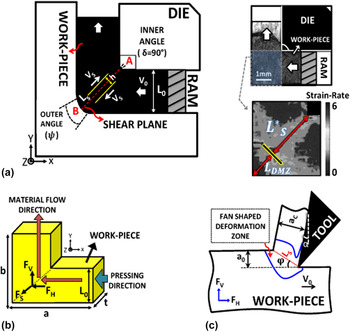
ECAP was performed on rectangular Pb samples. The die angle was δ = 90° [Fig. 2(a)]. Channel widths were set at 1 and 2 mm [Fig. 2(a)] and the ram was advanced at five different speeds (2, 5, 10, 20, and 30 mm/s). Sharp and round-corner dies featuring ψ = 0°, 45°, and 90° were tested [Fig. 2(a)]. In Fig. 2(a), inner and outer corners of ECAP die are marked as A and B, respectively.
Schematic of ECAP in a plane-strain configuration to measure the mechanics of deformation in simple shear using light and infra-red high-speed photography from the side view of the deformation zone. (a) The deformation parameters in ECAP are illustrated; the insets are the images of the material flow captured through the transparent sapphire window while imposing load on the RAM (top), the corresponding deformation zone obtained by DIC (bottom), respectively. (b) The horizontal and vertical forces measured along the X and Y directions using load cell and shear force along the direction of the shear plane calculated using measured horizontal and vertical forces. (c) Schematic of machining configuration, showing the deformation parameters.

No lubricant was used while performing ECAP to prevent interference with the optical and IR imaging systems. The width of the workpiece in the Z direction [Fig. 2(a)] was set at 2 mm. Tables I and II list the ECAP process parameters studied here along with the theoretical (assuming no friction between die wall and sample) von Mises equivalent strain for each condition, calculated using Reference Valiev and Langdon17 :
 $${\varepsilon _{{\rm{eq}}}} = {1 \over {\sqrt 3 }}\left[ {2\cot \left( {{{\delta + \psi } \over 2}} \right) + \psi \,{\rm{cosec}}\left( {{{\delta + \psi } \over 2}} \right)} \right]\quad .$$
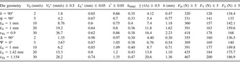
Deformation parameters for die with 2 mm channel width and different geometries listed: ram velocity (V
0), measured velocity along the shear plane using DIC
 $\left( {\mathop {{V_{\rm{S}}}}\nolimits^* } \right)$
, measured length of the shear zone using DIC
 $\left( {\mathop {{L_{\rm{S}}}}\nolimits^* } \right)$
[the inset of Fig. 2(a)], measured equivalent strain using DIC (ε∗), normalized length of the DMZ
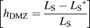 $\left[ {{h_{{\rm{DMZ}}}} = {{{L_{\rm{S}}} - \mathop {{L_{\rm{S}}}}\nolimits^* } \over {{L_{\rm{S}}}}}} \right]$
, average shear strain-rate in PDZ measured using DIC
 $\left( {\dot \gamma } \right)$
, calculated deformation thickness (h)
 $\left[ {h = {{\mathop {V_{\rm{S}} }\nolimits^* } \mathord{\left/ {\vphantom {{\mathop {V_{\rm{S}} }\nolimits^* } {\dot \gamma }}} \right. \kern-\nulldelimiterspace} {\dot \gamma }}} \right]$
, measured horizontal and vertical forces (F
H, F
V) along the X and Y directions [Fig. 2(b)] using load cell attached to die assembly, calculated force along the shear plane (F
S) using Eq. (2) [Fig. 2(b)].

Deformation parameters for die with 1 mm channel width and different geometries listed: ram velocity (V
0), measured velocity along the shear plane using DIC
 $\left( {\mathop {{V_{\rm{S}}}}\nolimits^* } \right)$
, measured length of the shear zone using DIC
 $\mathop {{L_{\rm{S}}}}\nolimits^*$
[the inset of Fig. 2(a)], measured equivalent strain using DIC (ε∗), normalized length of the DMZ
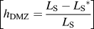 $\left[ {{h_{{\rm{DMZ}}}} = {{{L_{\rm{S}}} - \mathop {{L_{\rm{S}}}}\nolimits^* } \over {{L_{\rm{S}}}}}} \right]$
, average shear strain-rate in PDZ measured using DIC
 $\left( {\dot \gamma } \right)$
, calculated deformation thickness (h)
 $\left[ {h = {{\mathop {V_{\rm{S}} }\nolimits^* } \mathord{\left/ {\vphantom {{\mathop {V_{\rm{S}} }\nolimits^* } {\dot \gamma }}} \right. \kern-\nulldelimiterspace} {\dot \gamma }}} \right]$
, measured horizontal and vertical forces (F
H, F
V) along the X and Y directions [Fig. 2(b)] using load cell attached to die assembly, calculated force along the shear plane (F
S) using Eq. (2) [Fig. 2(b)].
The characterization of flow fields in the deformation zone during ECAP was performed using DIC. Deformation imposed by the advancing ram during ECAP results in motion of asperities inherently present on the surface of the workpiece. Asperities appear as high contrast features upon illumination [Fig. 2(a)]. Therefore, by tracking their motion through the sequence of optical images acquired by the high speed CCD camera during ECAP,
Reference Adrian18
deformation imposed by the advancing ram can be assimilated. Subsequently, using post-processing algorithms, velocity and displacement fields in the PDZ were generated. Thereafter, the strain-rate field in the deformation zone was generated using spatio-temporal differentiation of the displacement field,
Reference Adrian18,Reference Verhulp, Rietbergen and Huiskes19
from which morphological parameters of the ensuing PDZ were extracted for the different ECAP process parameters studied. The insets of Fig. 2(a) show examples of the flow behavior of the material and its corresponding deformation field obtained by DIC. In this figure,
 $\mathop {{L_{\rm{S}}}}\nolimits^*$
and L
DMZ are the length of shear zone and DMZ in the PDZ, respectively.
Deformation forces experienced by the ram along the X and Y directions—F H and F V [Fig. 2(b)] were measured by mounting the die assembly on a three directional load cell (Model# TR3D-B-4K-Michigan Scientific). The load cell was located on the base plate, interfacing the linear servo motor machine to the ECAP assembly [Fig. 1(a)]. The idealized (frictionless) deformation geometries are similar in both machining and ECAP. Both constitute simple shear within a narrow zone of thickness h. Reference Palmer and Oxley20 Hence, an upper bound analysis based approach similar to machining was used to analyze deformation forces during ECAP. In doing this, ECAP was considered equivalent to machining with a fixed geometry of PDZ assuming that the undeformed and deformed chip thicknesses (a 0 and a c, respectively) are equal. Reference Palmer and Oxley20 This implies a fixed shear plane angle (ϕ = 45°) during ECAP [Fig. 2(c)]. Therefore, using an approach similar to that in Ref. Reference Palmer and Oxley20, the force resolved along the nominal shear direction (F S), parallel to the shear plane was calculated using Reference Palmer and Oxley20,Reference Marusich and Ortiz21 :
 $${F_{\rm{S}}} = {F_{\rm{H}}}\cos \varphi - {F_{\rm{V}}}\sin \varphi \quad ,$$
where F H and F V are the horizontal and vertical forces, respectively, and ϕ (= 45°) is the shear angle.
In the aforementioned theory of machining, Reference Palmer and Oxley20 it is assumed that the average shear strain-rate in the PDZ is given by:
 $$\dot \gamma = {{{V_{\rm{S}}}} \over h}\quad ,$$
where V S is the shear velocity and h is the thickness of the deformation zone.
Equation (3) in fact relates the thickness of the PDZ (h) to the shear strain-rate
 $\left( {\dot \gamma } \right)$
and shear velocity (V
S). Here, empirical shear velocity (
 $\mathop {{V_{\rm{S}}}}\nolimits^*$
, measured by DIC) was calculated using
 $\mathop {{{\bi{V}}_S}}\nolimits^* = {{\bi{V}}_{exit}} - {{\bi{V}}_{entry}}$
, where
V
exit
and
V
entry
are the exit and entry velocity vectors, respectively. During ECAP,
 $\left| {{\bi{V}}_{exit}}} \right| = \left| {{\bi{V}}_{entry}}} \right|$
due to conservation of volume during plastic deformation. Therefore,
 $\mathop {{V_{\rm{S}}}}\nolimits^* = \left| {\mathop {{\bi{V}}_S}}\nolimits^* } \right| = \sqrt 2 \left| {{{\bi{V}}_{entry}}} \right|$
(Tables I and II).
Characterization of the mechanics of deformation was complemented with the measurement of the temperature field in the deformation zone using in situ calibrated IR thermography through a FLIR camera. Calibration was performed by coating a metallic sheet with black nonreflective stove paint to achieve uniform surface emissivity. This sheet was heated from room temperature (∼300 K) to 500 K in steps of 5 K and subsequently observed through the IR camera, which produced a certain number of counts for every temperature. By recording the counts and tallying with the preset temperatures, a calibration curve was produced. Calibrated accuracy ∼2 K was found to be possible in this temperature range. Using this curve, counts obtained from the camera during ECAP were used to produce the deformation zone temperature field. Prior to performing ECAP, the workpiece was coated with the black stove paint for obtaining uniform emissivity and a region close to the deformation zone was observed through the IR camera while performing ECAP.
III. RESULTS AND DISCUSSIONS
In the present study, ECAP was used to impose an effective strain of ∼1 after one pass and the thermomechanics in the PDZ was quantified as a function of the ram speed, channel width, and geometry of the die. In situ visible light and IR imaging were utilized to characterize the deformation. These characterizations were complemented by force measurements and the following sections give the results in detail. The result of calculations for each condition is given in Tables I and II. Furthermore, the value of an average equivalent strain (ε∗) near the middle of workpiece at PDZ was also measured empirically. This was done by integrating strain accumulated along the respective pathlines.
A. Strain-rate fields as a function of scale, geometry, and deformation speed
The results of in situ mechanical characterization of the PDZ during ECAP using DIC are summarized in Figs. 3 and 4. The motion of asperities on the surface of the workpiece undergoing ECAP was quantified and displacement field corresponding to the material flow was delineated in finite time intervals. The strain-rate tensor field
 ${\underline D ^{\rm{P}}}$
was thereafter calculated from this by numerical spatiotemporal differentiation using:
 $$\underline D ^{\rm{P}} = \left[ {\matrix{ {{{\partial ^2 u} \over {\partial x\partial t}}} & {{1 \mathord{\left/ {\vphantom {1 2}} \right. \kern-\nulldelimiterspace} 2}\left( {{{\partial ^2 u} \over {\partial y\partial t}} + {{\partial ^2 v} \over {\partial x\partial t}}} \right)} \cr {{1 \mathord{\left/ {\vphantom {1 2}} \right. \kern-\nulldelimiterspace} 2}\left( {{{\partial ^2 u} \over {\partial y\partial t}} + {{\partial ^2 v} \over {\partial x\partial t}}} \right)} & {{{\partial ^2 v} \over {\partial y\partial t}}} \cr } } \right]\quad ,$$
where u and v are displacements in the X and Y directions [Fig. 1(a)], respectively, and t is the time. The effective strain-rate field was calculated using:
 $${\dot \varepsilon ^{\rm{P}}} = \sqrt {{\textstyle{2 \over 3}}{{\underline D }^{\rm{P}}}:{{\underline D }^{\rm{P}}}} \quad ,$$
where “:” refers to the inner product.
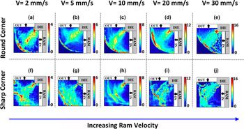
DIC of PDZ for 2 mm channel width in the dies with round and sharp corner radii for various ram velocities. The images show the strain-rate field changing with the curvature of the outer surface of the die as well as the deformation speed.

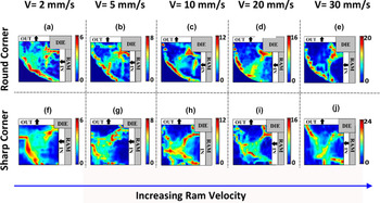
DIC of PDZ for 1 mm channel width in the dies with round and sharp corner radii for various ram velocities. The images show the strain rate field changing with the curvature of the outer surface of the die as well as the deformation speed.

It is evident from Fig. 3 that the PDZ during ECAP is localized in the vicinity of the intersection plane of the two channels, i.e., nominal shear plane. The morphology of the PDZ was found to be a function of the die geometry and the deformation rate (ram velocity). The same variation in the strain-rate was also found across the length of the PDZ. In Fig. 3, maximum intense strain-rate was found near the corner A and strain-rate decayed when approaching the outer corner B [A and B are marked in Fig. 2(a)]. Based on the morphological characteristics arising from inhomogeneity of deformation through its length, the PDZ is conventionally divided into two distinct zones: a narrow region close to the inner corner A extended to the center of the workpiece, and a fan shaped region adjacent to the outer corner B. Reference Stoica, Fielden, McDaniels, Liu, Huang, Liaw, Xu and Langdon6 In contrast to corner A shown in Fig. 3, corner B is also characterized by a DMZ as shown in the inset of Fig. 2(a). DMZs were seen across all the ECAP process parameters studied here. It was also seen that on increasing ram velocities, the shape of the PDZ adopts a more curved shape and dead-metal zone extends further into the center of the channel. This is observed in the insets of Figs. 3(h), 3(i), and 3(j).
It was seen that at ram velocities above 10 mm/s, the PDZ adopts a more curved morphology, compared with the conventionally anticipated straight PDZ [insets of Figs. 3(a), 3(b), 3(f), and 3(g)] that is oriented along the intersection plane of the entry and exit channels. This is illustrated in the insets of Figs. 3(d), 3(e), 3(i), and 3(j). The aforementioned curvature becomes more prominent at ram velocities of 30 mm/s. It was seen that the ensuing PDZ here features a rigidly moving front of the material ahead of the ram with deformation concentrated in its periphery [insets of Figs. 3(e) and 3(j)].
The PDZs resulting in ECAP with a channel width of 1 mm exhibited few prominent differences with respect to those in channel width of 2 mm (Fig. 4). It was seen that PDZs in the former are more localized around the shear plane for both round and sharp corner dies, implying a decrease in h with reducing channel width. However, this scaling behavior disrupts at 1 mm channel width as evidenced from the formation of proportionately large dead-metal zones close to the outer corner B. This was delineated by normalizing the dimensions of the DMZ using
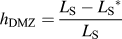 ${h_{{\rm{DMZ}}}} = {{{L_{\rm{S}}} - \mathop {{L_{\rm{S}}}}\nolimits^* } \over {{L_{\rm{S}}}}}$
, where L
S is the theoretically anticipated length of PDZ (determined by ECAP die dimensions and geometry) and
 $\mathop {{L_{\rm{S}}}}\nolimits^*$
is the empirically observed counterpart. For measuring
 $\mathop {{L_{\rm{S}}}}\nolimits^*$
, the DMZ close to the outer corner B [Fig. 2(a)] was not considered as part of the PDZ of ECAP.
Strain-rate field maps from DIC highlight the distinction between these zones as a local maximum due to the large gradient in the flow velocity of the material at their interface. This is because the DMZ is almost stationary while rest of the PDZ undergoes flow imposed by the advancing ram. Facilitated by this feature, we measured empirically and subsequently verified results using velocity fields, which highlight DMZ as a near stationary zone. The results are given in Tables I and II.
The h DMZ values for various conditions are listed in Tables I and II. As seen, DMZs during ECAP with smaller channel width (1 mm) are larger compared with those in the die with channel width (2 mm) particularly at higher ram velocities for the die with sharp corner angle B [insets of Figs. 4(i) and 4(j)]. This is due to the relative increase in the surface-to-volume of the material undergoing deformation for smaller channel width (1 mm) which is approximately 1.5 times larger than that in the die with 2 mm channel width for the geometries used in these experiments.
It is seen in Fig. 4 that deformation is localized in three distinct regions during ECAP with round corner die geometries (corner B), particularly at lower ram velocities [insets of Figs. 4(a)–4(c)]. The three zones comprise the shear plane, the inlet where the curvature of the corner commences and the analogous point where the curvature ends at the exit. The geometry of deformation zone demonstrates an unexpected size effect, where the gradual deformation in the 2 mm channel in an integral deformation zone is replaced with discrete regions of concentrated deformation in the 1 mm channel. However, this effect disappears at higher ram velocities (V > 10 mm/s) and we observe a restoration of an integral deformation zone [insets of Figs. 4(d) and 4(e)]. For round and sharp corners in both 1 and 2 mm channel widths a curved deformation zone is observed for ram velocities >10 mm/s [see the insets of Figs. 3(d), 3(e), 3(i), and 3(j) and Figs. 4(d), 4(e), 4(i), and 4(j)].
B. Analysis of shear zone parameters and its correlation to shear strain-rate
To understand the effect of ECAP process parameters (ram velocity, geometry, etc.) on the mechanics of deformation, we measured the average effective strain rate in the PDZ for the various conditions. Tables I and II report the empirically obtained values. These were obtained from zones in the PDZ by area averaging. Empirically observed lengths of the zones along the intersection plane of the entry and exit channels [
 $\mathop {{L_{\rm{S}}}}\nolimits^*$
, see Fig. 2(a)] are also reported in Tables I and II.
Given the similarities between ECAP and machining, we drew insights from machining literature. Characteristics of the PDZ during machining (in machining relevant process parameters) were delineated by Oxley
Reference Oxley and Hastings22
who showed that the average strain rate prevalent within the aforementioned zone is proportional to the parameter
 ${{{V_{\rm{S}}}} \over {{L_{\rm{S}}}}}$
, i.e.,
 $\dot \gamma = C{{{V_{\rm{S}}}} \over {{L_{\rm{S}}}}}$
. In this equation, V
S is the shear velocity, which is the velocity of the material resolved along the shear plane (Sec. II) and L
S is the length of the PDZ that is approximated as a plane. The parameter C (the Oxley parameter) was found to be constant for a given material and was shown to be approximately equal to
 ${{{L_{\rm{S}}}} \over h}$
implying constancy of
 ${{{L_{\rm{S}}}} \over h}$
for a material.
Reference Oxley and Hastings22
This relation predicts that the thickness of the deformation zone h is directly proportional to the length of the deformation zone L
S. Validity of these relations were verified across a wide range of machining process parameters (e.g., cutting speeds and undeformed chip thicknesses
Reference Oxley and Hastings22
). Based on arguments of similarities in deformation geometries, it can be expected that the analogous relations hold for ECAP (a simple shear based plastic deformation process, akin to machining).
However, empirical observations (Tables I and II) show that unlike in machining, thickness of the deformation (h) in ECAP of Pb not only depends on the length of the deformation zone
 $\left( {\mathop {{L_{\rm{S}}}}\nolimits^* } \right)$
but also on the speed of advancement of the ram (i.e., deformation speed).
Reference Lapovok, Tóth, Molinari and Estrin23
Although Eq. (3) somewhat overestimates h for ECAP with respect to empirical values obtained from the strain-rate fields (Figs. 3 and 4), Tables I and II show a clear increasing trend in h, with increasing ram velocity. It appears that increasing ram velocity instigates the formation of a larger DMZ, which results in a smaller
 $\mathop {{L_{\rm{S}}}}\nolimits^*$
. However, this results in a more diffuse deformation zone as opposed to the conventionally anticipated thinner deformation zone.
Deformation zone thickness (h) in ECAP was also observed to be influenced by the die geometry. For instance, h was found to be higher during ECAP with a 1 mm wide channel when the round outer corner was used, compared to the sharp outer corner counterpart. This is a consequence of the large curvature of the outer corner (ψ = 90°), which has been previously shown to influence ensuing deformation characteristics during ECAP (Fig. 4).
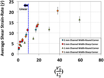
To probe this further, we plotted the average shear strain-rates
 $\dot \gamma$
versus the empirical
 $\left( {{{\mathop {{V_{\rm{S}}}}\nolimits^* } \over {\mathop {{L_{\rm{S}}}}\nolimits^* }}} \right)$
for each set of experiments (Fig. 5). It is evident from this diagram that a linear relationship is only valid for
 ${{\mathop {{V_{\rm{S}}}}\nolimits^* } \over {\mathop {{L_{\rm{S}}}}\nolimits^* }}$
< 10. For larger values of
 ${{\mathop {{V_{\rm{S}}}}\nolimits^* } \over {\mathop {{L_{\rm{S}}}}\nolimits^* }}$
,
 $\dot \gamma$
strays away from linear behavior with respect to
 ${{\mathop {{V_{\rm{S}}}}\nolimits^* } \over {\mathop {{L_{\rm{S}}}}\nolimits^* }}$
. Nonetheless, there appears to be a monotonic variation between the average strain-rate as a function of
 ${{\mathop {{V_{\rm{S}}}}\nolimits^* } \over {\mathop {{L_{\rm{S}}}}\nolimits^* }}$
(i.e.,
 $\dot \varepsilon \propto {{\mathop {{V_{\rm{S}}}}\nolimits^* } \over {\mathop {{L_{\rm{S}}}}\nolimits^* }}$
). It is apparent that friction plays a role in determining the shape of DMZ, which in turn influences the
 ${{\mathop {{V_{\rm{S}}}}\nolimits^* } \over {\mathop {{L_{\rm{S}}}}\nolimits^* }}$
parameter through a change in
 $\mathop {{L_{\rm{S}}}}\nolimits^*$
, eventually manifesting in the average strain rate. However, the influence of speed on the DMZ emerges at larger speeds wherein larger
 ${{\mathop {{V_{\rm{S}}}}\nolimits^* } \over {\mathop {{L_{\rm{S}}}}\nolimits^* }}$
is seen through a decrease in
 $\mathop {{L_{\rm{S}}}}\nolimits^*$
upon increasing rate of deformation, resulting in the loss of linearity between average strain rates and
 ${{\mathop {{V_{\rm{S}}}}\nolimits^* } \over {\mathop {{L_{\rm{S}}}}\nolimits^* }}$
.
Average of strain-rate versus shear velocity over shear length for different ECAP conditions, suggesting a universality of its scaling as a function of geometry and deformation rate.

C. Evolution of effective strain on pathlines through the PDZ of ECAP
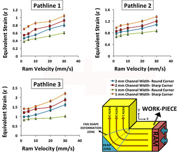
The strain imposed on the workpiece was calculated along the pathlines of the material flow that went through the PDZ, identified using DIC. The results were obtained for three pathlines located in the upper, middle, and lower regions of the workpiece (Fig. 6). The calculation was performed by integrating the increments of strain accumulated in discrete sections of the pathlines of the material. The average values of effective strain (ε) obtained along the material flow pathlines in PDZ are plotted against the ram velocity for each processing condition (Fig. 6).
Equivalent strain (ε) in the deformation zone along the three pathlines located in the upper, middle, and lower regions of the workpiece for 2 and 1 mm channel widths with round and sharp corners. Schematic on the bottom right shows the location of pathlines and the fan shaped deformation zone in which the strain value was measured.

Based on Eq. (1), the magnitude of equivalent plastic strain (ε) imposed on the workpiece undergoing ECAP in one pass is dependent only on the inner angle (δ) and outer corner angles (ψ) that are marked in Fig. 2(a). The strains imposed are 1.154 for sharp outer corner (ψ = 0) and 0.96 and 0.9 for round outer corner (ψ = 45°, ψ = 90°) dies, respectively. They are assumed to be uniform throughout the workpiece. However, it is evident from Fig. 6 that the measured values of equivalent strain across the thickness of the workpiece vary with scale, die geometry, deformation speed (ram velocity), and location in the workpiece. Pathline 3, which corresponds to a zone close to the outer corner B of the die consistently, exhibits the highest value of strain, compared with pathlines 1 and 2. This is due to the influence of the DMZ, which forms adjacent to the outer corner and presumably influences pathline 3 more than pathlines 1 and 2. Thus, it can be expected that more prominent DMZs would influence pathline 3 more significantly and resulting in larger strain inhomogeneity. This is indeed true as seen by a comparison of ECAP with a sharp outer die corner (channel width = 1 mm, ram velocity V = 30 mm/s) with a round outer die corner (channel width = 2 mm, ram velocity V = 2 mm/s). The former exhibits the largest normalized DMZ in the conditions studied and shows a strain inhomogeneity of ∼1.1. On the other hand, the latter features the smallest normalized DMZ and shows a significantly smaller strain inhomogeneity of ∼0.5. Here, strain homogeneity refers to ε3 − ε1, where ε3 refers to strain accumulated by pathline 3, etc. Dimensions of the normalized DMZ were calculated using
 ${{{L_{\rm{S}}} - \mathop {{L_{\rm{S}}}}\nolimits^* } \over {{L_{\rm{S}}}}}$
, where L
S refers to the idealized length of the shear plane and
 $\mathop {{L_{\rm{S}}}}\nolimits^*$
refers to that calculated empirically using DIC (Sec. B).
It remains to be seen how ram velocity influences dimensions of the DMZ. However, an increase in the ram velocity caused an increase in the normalized dimensions of the DMZ (Tables I and II) across the ECAP process parameters studied here. This change significantly influences the mechanics of material flow through the PDZ of ECAP, which plays a role in instigating the deviation of expected strain rate from
 $\dot \gamma = C{{{V_{\rm{S}}}} \over {{L_{\rm{S}}}}}$
as described in the previous paragraph. As discussed in Sec. B, there is a deviation from the linearity beyond the cut off (Fig. 5) that may promote instability in the material flow. Here, with increasing ram velocity or scaling the process down, we also obtain higher deviation of the average equivalent effective strain from the theoretical value calculated using Eq. (1). This also suggests strain localization for these conditions that can promote shear band formation and hence instability in the PDZ.
D. IR thermography of PDZ and analysis of temperature increment
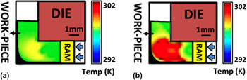
Following the characterization of PDZ using DIC, the temperature field was empirically characterized using IR imaging. Figure 7 illustrates IR thermographs of PDZ obtained for two conditions: 10 and 30 mm/s ram speeds for 2 mm channel width with round corner. A portion of the work of the plastic deformation is dissipated as heat, which in turn modifies the temperature field in the deformation zone and can lead to a thermomechanically-coupled state. Reference Shekhar, Cai, Wang and Shankar24 In addition to the used die geometry, this thermomechanical coupling also affects the mechanics of material flow. Reference Abolghasem, Basu and Shankar25
IR thermograph for ECAP of lead in plane strain configuration. The temperature rise in the deformation zone is illustrated in the die with 2 mm channel width and for (a) 10 mm/s and (b) 30 mm/s ram velocities. It shows that the temperature increment is higher for 30 mm/s ram velocity. From the temperature field, the extension of the deformation zone or the volume of the material undergoes deformation can be observed. Because of the accumulation of the material ahead of the ram and behind the shear plane, particularly at higher ram velocity, the PDZ is more extended in the entry channel.

We find that the temperature rise is localized in the vicinity of the deformation zone as expected from the results of DIC. It is also found that the higher ram velocity of 30 mm/s [Fig. 7(b)] results in a much more extensive zone, simultaneously involving higher magnitudes of temperature-rise. We also find that the IR thermography reveals an increase in the thickness of the deformation zone with increasing deformation speeds, which coincide with that observed in the strain-rate fields from DIC. This might be a combined effect of the higher rate of heat dissipation in the PDZ in larger ram velocities and the effect of thickening of the deformation zone as seen empirically in strain rate fields, obtained from DIC.
During ECAP, a significant portion of plastic work is converted into heat in the PDZ. For adiabatic conditions, temperature rise (ΔT) is given by Reference Kim26,Reference Dong, Zhang, Alexandrov and Wang27 :
 $$\Delta T = \eta {{\sigma \varepsilon } \over {\rho c}}\quad ,$$
where η is the percentage of total plastic work that is converted to heat, which is usually approximated as ∼0.9 (Ref. Reference Quang, Krishnaiah, Hong and Kim28). σ, ε, ρ, and c are flow stress at the PDZ, deformation strain, density, and the heat capacity of the workpiece, respectively. The values of the physical properties for Pb are: ρ = 11340 kg m−3, c = 130 J kg−1 K−1. For σ in Eq. (6) we utilized the deformation force resolved along the shear plane (F S). This calculation was performed using Eq. (2) with force data from Tables I and II. This approach for estimating the temperature field using the force resolved along the “shear plane” is reminiscent of that used in the machining literature, where it has been used to obtain reliable estimates of the temperature rise in analogous thermomechanically-coupled SPD. Reference Palmer and Oxley20 The relevant flow stress (σ) in the PDZ was obtained by dividing F S over the area of shear plane (t × L S), where t is the thickness of the sample, which is 2 mm in both ECAP dies with 1 and 2 mm channel widths. The average equivalent strains (Tables I and II) measured from the DIC were used for each condition. The temperature rise for 10 and 30 mm/s ram velocities for η = 0.9 was obtained to be 20 and 31 °C, respectively.
In contrast to these calculations, IR thermography revealed significantly lower temperature rise of 6 and 12 °C for 10 and 30 mm/s ram velocities, respectively. One of the assumptions we made in using Eq. (6) is that 90% of plastic work is converting to heat which is not always the case especially for strains less than one. Reference Ravichandran, Rosakis, Hodowany and Rosakis29,Reference Mason, Rosakis and Ravichandran30 With the aid of in situ techniques for measuring temperature rise during metal forming processes, it has been argued that for strains less than 1, the value of η can decrease from conventional assumption (0.9) to even 0.3. Reference Ravichandran, Rosakis, Hodowany and Rosakis29 In addition, Eq. (6) is likely true only for adiabatic processes where heat diffusion is completely neglected. Reference Eisenlohr, Gutierrez-Urrutia and Raabe31 Here, the heat transfer of the workpiece–tooling interfaces is likely to modify the temperature field. ECAP occurs in a fully enclosed die, where the relatively simplistic assumptions that might be acceptable say, in thermal models for machining produce an overestimate of the temperature rise in ECAP.
Previous efforts at modeling temperature rise during ECAP while seeking better agreement with experimental observations were directed toward modifying the heat dissipation model [Eq. (6)] by incorporating contributions from friction and process parameters such as speed and geometry of die. In these models, theoretical equivalent effective strain obtained from Eq. (1) and nominal material strengths were used. Reference Kim, Quang, Seo, Hong, Baik, Lee and Nghiep32,Reference Yamaguchi, Horita, Nemoto and Langdon33 Low (3–6 K) to moderate (14–26 K) temperature rise was seen in these studies across small to medium deformation speeds for a range of materials. Reference Nishida, Ando, Nagase, Lim, Shigematsu and Watazu34 These estimates were empirically verified by integrating a thermocouple within the workpiece during ECAP. However, heat dissipation models utilizing theoretical strains and nominal strengths resulted in overestimation of temperature rise across the process parameters studied here. This is presumably due to somewhat smaller effective strains compared to theoretical estimates imposed on the workpiece during our experiments (Tables I and II) and conventional assumption for η. To rectify this, we used the empirically recorded values for thermomechanical parameters (from situ characterization and force measurements) in the heat dissipation model. This resulted in better estimates of temperature rise in our study, as substantiated by empirical IR thermography measurements.
E. Material rotation field in PDZ
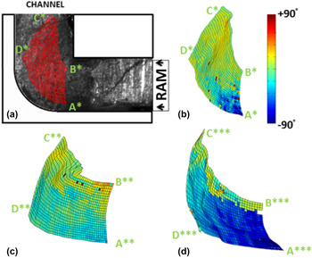
The rotational component of deformation imposed during ECAP of Pb was determined from empirically measured and quantified pathlines using DIC. Figure 8(a) shows the results of DIC for ECAP with 2 mm/s ram velocity for 2 mm channel width with round corner. Also illustrated in Fig. 8(b) is the corresponding rotation field (in degrees) that was obtained from these results.
(a) Final configuration of a grid of points obtained from DIC on high-speed image sequence acquired during ECAP. Deformation conditions: 2 mm/s ram velocity, 2 mm channel width with round corner. (b) Rotation field corresponding to deformation conditions in (a). (c) Rotation field for deformation conditions: 20 mm/s ram velocity, 2 mm channel width with round corner. (d) Rotation field for deformation conditions: V = 20 mm/s ram velocity, 2 mm channel width with sharp corner. (* Refers to deformed configuration).

The rotation field was obtained by first calculating the deformation gradient tensor fields. This was done using:
 $$F = \left( {\matrix{ {{{\partial u} \over {\partial x}}} & {{{\partial u} \over {\partial y}}} \cr {{{\partial v} \over {\partial x}}} & {{{\partial v} \over {\partial y}}} \cr } } \right)\quad ,$$
where u and v are the displacements in the X and Y directions, respectively. Thereafter, polar decomposition was performed whereby rotation tensor R could be obtained from F. This was done by reducing the deformation gradient tensor to the right Cauchy-Green tensor by performing the operation:
 $$C = {F^{\rm{T}}}F\quad .$$
From the eigenvalues of the Cauchy-Green tensor C(=λ i 2) and eigenvectors of C(= W i ), the stretch tensor is obtained as:
 $$U = \sum\nolimits_i {{\lambda _i}{{\bi{W}}_i} \otimes {{\bi{W}}_i}} \quad ,$$
where ⊗ is the tensor product. Eventually the rotation tensor R is obtained by performing:
 $$R = F{U^{ - 1}}\quad .$$
Subsequently, the rotation tensor R is related to the finite rotation angle by the relation:
 $$R = \left( {\matrix{ {\cos \theta } & { - \sin \theta } \cr {\sin \theta } & {\cos \theta } \cr } } \right)\quad .$$
Doing this for every point on the grid, a rotation field was obtained for the material undergoing deformation during ECAP [Figs. 8(b)–8(d)]. Figure 8(a) shows the final configuration of a grid of points that was obtained from DIC using a sequence of high speed images of the ECAP process with deformation conditions: 2 mm/s ram velocity, 2 mm channel width with round corner. Figures 8(b)–8(d) show the rotation fields corresponding to ECAP with deformation conditions: 2 mm/s ram velocity, 2 mm channel width with round corner; 20 mm/s ram velocity, 2 mm channel width with round corner; 20 mm/s ram velocity, 2 mm channel width with sharp corner, respectively. That was obtained from their corresponding grids using the procedure described above. Furthermore, for obtaining these images, the DIC routine was stopped at an instant when a portion of the grid near the right edge [e.g., closer to A*B* in Fig. 8(b)] was about to enter the deformation zone whereas the top left corner [e.g., closer to C* in Fig. 8(b)] had crossed the deformation zone. Consequently, there is an unambiguous variation in the corresponding rotation fields which change from strongly negative (anticlockwise near A*, shown in blue) to moderately positive (clockwise near C*, shown in red). In fact, the average rotation angles calculated near points A*, B*, C* are −59°, 1.1°, 12.6°, respectively [Fig. 8(a)]. In comparison, the average rotation angles calculated near points A**, B**, C** were −32.5°, 28.5°, 17.3°, respectively [Fig. 8(c)] and A***, B***, C*** were −86.5°, 11.0°, −2.9°, respectively [Fig. 8(d)], corresponding to 20 mm/s ram velocity, 2 mm channel width with round corner; 20 mm/s ram velocity, 2 mm channel width with sharp corner, respectively.
The deformation history is complicated due to effects arising out of friction and pile up near the ECAP die corner. In fact, we have already seen in Fig. 8 that the regions close to the bottom right of the grids exhibit strongly negative rotation fields. This can be attributed to frictional effects arising from the bottom face of the channel resulting in anticlockwise rotation. Using a similar reasoning, the positive rotation closer to the top right corner of the grid can be explained, as the top face of the ECAP die would tend to rotate the material in a clockwise fashion. It is also clear from Figs. 8(b)–8(d) that as the material progresses through the deformation zone, the anticlockwise rotation caused by the bottom face is reversed whereby the material closer to C*D* exhibits a less negative rotation field (when compared to the material closer to A* which has undergone deformation imposed by the DMZ).
The observations mentioned here suggest that deformation zone heterogeneities are instigated by certain (sharp) deformation geometries and process parameters (high velocities). These heterogeneities are bound to result in accelerated microstructure evolution due to strain path changes intrinsically associated with the deformation zone of ECAP. Such strain path changes are known to cause flow instabilities Reference Li, Hoferlin, Bael, Houtte and Teodosiu35,Reference Paul, Baudin and Brisset36 as also evidenced in our experiments. For example, sharp corner die exhibited large gradients in angular rotation [previous paragraph, Fig. 8(d)], simultaneous with thin deformation zone morphologies indicative of flow localizations. On the other hand, round corner dies exhibited diffuse deformation zone geometries compared to sharp corner dies, especially at lower speeds, i.e., no flow localizations.
IV. CONCLUSIONS
ECAP was performed on commercially pure lead and the effect of geometric scaling and deformation rates on ensuing deformation zone was studied. The thermomechanics prevalent in the deformation zone was characterized in situ using DIC and IR thermography. A specially designed ECAP die housing an optical and IR transparent sapphire window was utilized for thermomechanical characterization. It was seen that, as conventionally observed in ECAP process, deformation zone is confined in the region of two intersecting channels. It was shown that deformation zone is divided in two regions: PDZ and DMZ. Using in situ analysis of deformation zone, it was shown that varying the geometry and deformation rate influences the mechanics of the formation of PDZ and DMZ.
The deformation zone of ECAP is similar to that in machining where simple shear deformation occurs in a narrow shear zone. It was found that, similar to machining, the thickness of PDZ decreases with channel's dimensions. However, unlike machining process, in ECAP it increases with increasing deformation rate. The average strain-rate in the PDZ scaled linearly in proportion to
 ${{\mathop {{V_{\rm{S}}}}\nolimits^* } \over {\mathop {{L_{\rm{S}}}}\nolimits^* }}$
till a threshold ∼10. For larger
 ${{\mathop {{V_{\rm{S}}}}\nolimits^* } \over {\mathop {{L_{\rm{S}}}}\nolimits^* }}$
values, this scaling was no longer valid although a monotonic relation between the average strain rate and
 ${{\mathop {{V_{\rm{S}}}}\nolimits^* } \over {\mathop {{L_{\rm{S}}}}\nolimits^* }}$
persisted. The results from empirically measured strain parameter showed a larger inhomogeneity in deformation for higher values of
 ${{\mathop {{V_{\rm{S}}}}\nolimits^* } \over {\mathop {{L_{\rm{S}}}}\nolimits^* }}$
across the length of PDZ. Additionally, at higher
 ${{\mathop {{V_{\rm{S}}}}\nolimits^* } \over {\mathop {{L_{\rm{S}}}}\nolimits^* }}$
, the value of the average effective strain increases and its larger deviation from the theoretically predicted strain in PDZ can be an indication of strain localization and ensuing shear banding and instability in material flow.
Based on the similarity of deformation zone characteristics between machining and ECAP, theoretical estimates of temperature rise in the deformation zone were performed using this model and results were observed to be in reasonable agreement with empirical counterparts.
Finally, the rotation fields of ECAP found by DIC analysis were shown to be affected by mechanics of formation of PDZ and DMZ. Broadening of DMZ under certain conditions results in a negative rotation of the material elements that also suggests more instability in imposed deformation.
ACKNOWLEDGMENT
Support from the National Science Foundation grants 1030265 and 1233909 is gratefully acknowledged.