Introduction
Over the past several decades, there has been considerable interest in converting mechanical energy into electrical energy. This can be achieved through engineered electrostatic or electromagnetic systems, as well as with piezoelectric materials.[Reference Roundy, Wright and Rabaey1–Reference Beeby, Tudor and White4] Although electromagnetic induction is promising for large-scale applications, piezoelectrics are generally considered the best candidates for small-scale devices, such as microelectromechanical systems, while maintaining useful output power. Most current technologies, however, are based on cantilevers, where the power is maximized at the resonant frequency, and achieving a broadband vibrational energy harvester has been elusive thus far. Previous works have attempted to flatten the frequency dependence of the power output by developing an array of cantilevers with different lengths, and therefore resonance frequencies,[Reference Tang, Yang and Soh5] tuning the dimensions of a novel cantilever design to move two different resonant modes closer,[Reference Sharpes, Abdelkefi and Priya6, Reference Abdelmoula, Sharpes, Abdelkefi, Lee and Priya7] or utilizing non-linear oscillations through a magnetic tip mass with two bi-stable states.[Reference Erturk, Hoffmann and Inman8, Reference Yang, Wen, Li, Dai and Li9] One other promising candidate, recently under development, is the use of an induced phase transition in relaxor ferroelectric single crystals of Pb(In1/2Nb1/2)O3–Pb(Mg1/3Nb2/3)O3–PbTiO3 (PIN-PMN-PT). By applying a pre-stress close to the critical stress for the phase transition, the power density of the single crystal is on par with that of other materials operating under resonance, while the energy density per cycle is two orders of magnitude (~100×) larger than linear piezoelectric materials.[Reference Finkel, Benjamin and Amin10, Reference Pérez Moyet, Stace, Amin, Finkel and Rossetti11]
Another active area of development of vibrational energy harvesters is a move toward magnetoelectric (ME) composites, consisting of piezoelectric and magnetostrictive phases coupled through strain. The addition of the magnetostrictive component has been shown to enhance the total generated power of the harvester.[Reference Priya, Ryu, Park, Oliver, Choi and Park12, Reference Bai, Wen, Yang, Li, Qiu and Zhu13] Further, because of the coupling of the magnetic and electric order parameters, these materials can also be used for multimodal harvesting through the strain generated in the magnetostrictor giving rise to a usable voltage in the piezoelectric component.[Reference Dong, Zhai, Li, Viehland and Priya14] Thus, ME composites open up the possibility of scavenging energy from magnetic, mechanical, and/or thermal stimuli.
We have previously demonstrated that the use of a hybrid ME device allowed us to drive the phase transformation in PIN-PMN-PT through the application of a changing magnetic field to a magnetostrictive element.[Reference Finkel, Pérez Moyet, Wun-Fogle, Restorff, Kosior, Staruch, Stace and Amin15] The two materials are held at a mechanical pre-stress to allow for a small change in stress to produce a large voltage. While the overall concept was verified, the magnetic field produced in this previous work was generated with a solenoid coil requiring very high current and no way to incorporate a vibrational excitation. In this work, we use finite element analysis (FEA) to study the response of an Fe81Ga19 (Galfenol) rod for various movements of an external permanent magnet that is used for excitation of the system and the results are compared with an prototype system. The ultimate design goal is to increase the power density (for large excitations) or decrease the acceleration required to produce the voltage (lower the threshold excitation for triggering the transition). This work thus represents a move toward a packaged, standalone prototype device based on a ME harvester generating a voltage due to a phase transformation.
Experimental
Magnetostriction under compressive stresses was measured with a conventional (MTS 858) load frame with a custom-made sample holder consisting of a magnetic field coil, a pick-up coil to measure the magnetization, and a Hall probe to measure the magnetic field. The stress range was −3.5 to −125.6 MPa. Strain was measured by averaging two strain gages (Micro-Measurements WK-06-500GB-350) mounted on opposite sides of the sample.[Reference Wun-Fogle, Restorff, Clark, Dreyer and Summers16]
Magnetic flux density through a Galfenol rod in various magnetic circuit configurations was calculated using two-dimensional FEA software (FEMM, http://www.femm.info). For the simulation, a high strength rare-earth magnet (NdFeB, neodymium–iron–boron) was used to provide the magnetic field input to the system. The permeability of the Galfenol alloy was considered to be nonlinear during the simulation.
Results and discussion
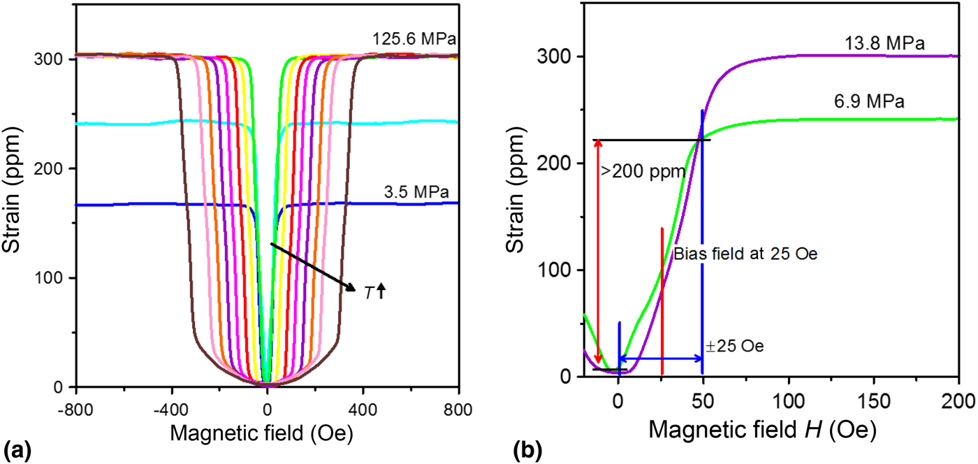
The properties of FeGa under various levels of static compressive stress have previously been demonstrated,[Reference Clark, Wun-Fogle, Restorff and Lograsso17, Reference Mahadevan, Evans and Dapino18] and several representative curves are shown in Fig. 1. It is clear that as the stress is increased, the saturation magnetostriction is maximized. However, at the same time, the magnetic field needed to attain the large jump in strain is also increased. For the energy harvester, the Galfenol needs to apply enough stroke to the PIN-PMN-PT crystal to induce the phase transition, but in order to minimize the overall size and weight of the device, large permanent magnets to apply high bias fields are not desirable. As a result, the stress experienced by the Galfenol rod is an important parameter to tune the overall performance of the energy harvester. A mid-range stress (7–14 MPa) is therefore targeted based on this analysis.
(a) Magnetostriction versus magnetic field for Galfenol at different compressive stresses. (b) The AC magnetic field that would be needed to produce sufficient stroke to induce the phase transition in a pre-stressed PIN-PMN-PT crystal.

This change in both total amplitude of displacement as well as slope has implications for the selection of the magnetostrictor itself. By adjusting the diameter of the Galfenol rod, we can optimize the applied force to both the piezoelectric and magnetostrictive elements to both minimize the magnetic field needed to achieve large strain in the Galfenol while applying the correct pre-stress to the piezocrystal so that it is near the critical point. This allows for a fixture where the FeGa and PIN-PMN-PT are in direct contact with each other, which will reduce the complexity of the device as compared with the previous iteration where a separate mechanical pre-stress was required for the crystal.
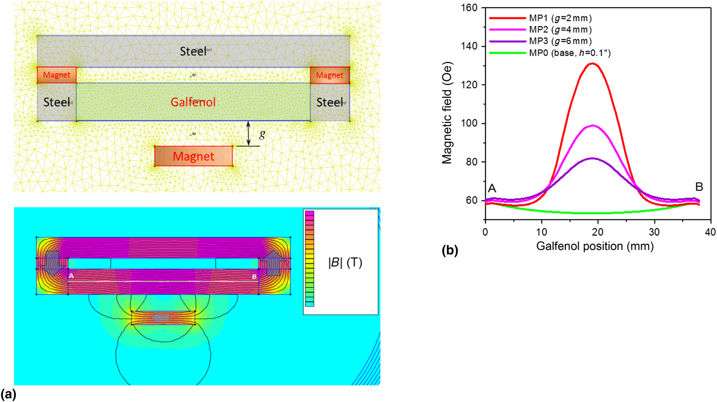
We then consider using a rotating permanent magnet to change the magnetic field seen by the Galfenol rod, to determine the motion required to achieve full stroke from the rod. The change in the internal magnetic field of a Galfenol rod (2 in. long, 1/4 in. diameter) was calculated with and without a flux return as shown in Fig. 2. Bias magnets were incorporated due to their necessity for actuating the rod in the linear portion of the magnetostriction curve. A NdFeB magnet (N-42, a nominal energy product of 42 MGOe) was placed at fixed distances away from this rod (defined as g), and the change in the magnetization along the length of the Galfenol was calculated. We can see that for between g = 2 and 6 mm, a maximum difference of ~50 Oe is expected. Based on the analysis of the magnetostriction curves for our chosen stress levels, this is within the range of magnetic field change needed to realize the maximum strain from a biased Galfenol rod.
(a) FEA model of Galfenol at the optimal bias magnetic field as configured with a flux return, and (b) the effects of a permanent magnet at various distances from the Galfenol rod are shown by evaluating the magnetic field seen along the length of the rod.

However, this linear displacement of a permanent magnet is very limited in terms of the modalities of vibration that could be converted into electrical energy. There have been several methods previously proposed in the literature that focus on converting linear motion to rotation or otherwise expanding the number of events per cycle to increase power density. Several groups have proposed a Halbach array to amplify the total energy per period.[Reference Zhu, Beeby, Tudor and Harris19, Reference Salauddin, Halim and Park20] Oscillations between two bi-stable states will also increase the energy for lower displacement or accelerations.[Reference Erturk, Hoffmann and Inman8, Reference Yang, Wen, Li, Dai and Li9] In addition, to optimize systems for low-frequency excitations such as those excited by human activity, several previous papers have focused on the conversion of linear vibration to the rotation of a pendulum[Reference Spreemann, Manoli, Folkmer and Mintenbeck21] or spherical rolling magnets to create a changing magnetic flux.[Reference Bowers and Arnold22, Reference Moss, Hart, Burke and Carman23] In moving forward, we now consider the possibility of the time varying magnetic field (B AC) produced by rotation, either with an unbalanced pendulum or a rotating magnetic ball.
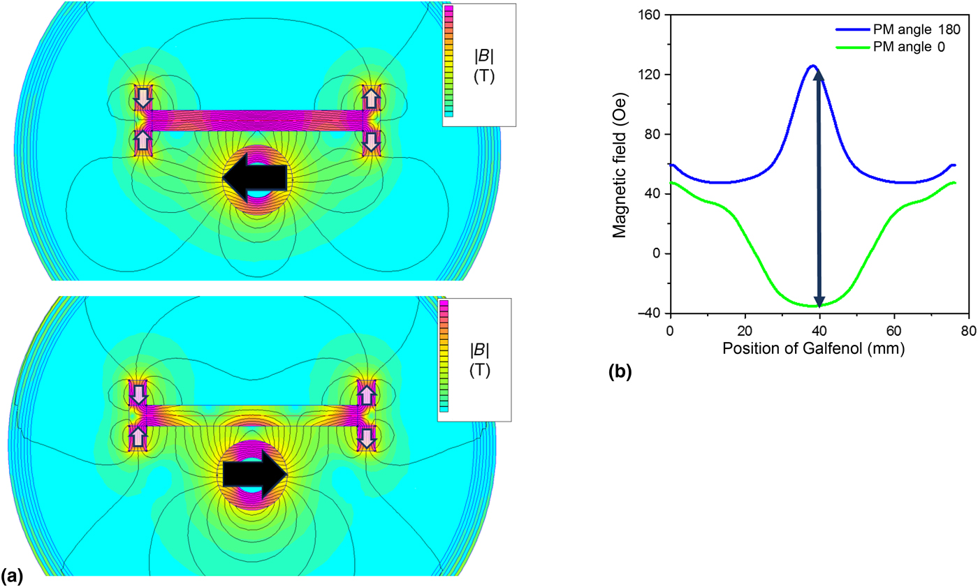
To evaluate this case, the distance to the permanent magnet in the 2D FEA is now fixed but the direction of the magnetization is rotated by 180° with respect to the length of the Galfenol rod (Fig. 3). The flux return was removed to achieve higher magnetic flux density variation. Even without the flux return, the rotation of the magnet is expected to result in over a 150 Oe change in magnetic field. Again, this is more than sufficient to achieve the maximum strain in the Galfenol with a proper bias field. This indicates that even less than a 180° rotation could be sufficient for actuation in the proposed energy harvester design, with the minimum rotation and the properties of the device (e.g., mass and friction) determining the lowest acceleration that could be exploited to induce the phase transition in the piezocrystal.
(a) The effects of a rotating permanent magnet (direction of magnetization shown with an arrow) at a fixed distance from a Galfenol rod with optimal bias field provided by several permanent magnets. (b) The maximum change in magnetic field as observed by the rod is over 150 Oe.

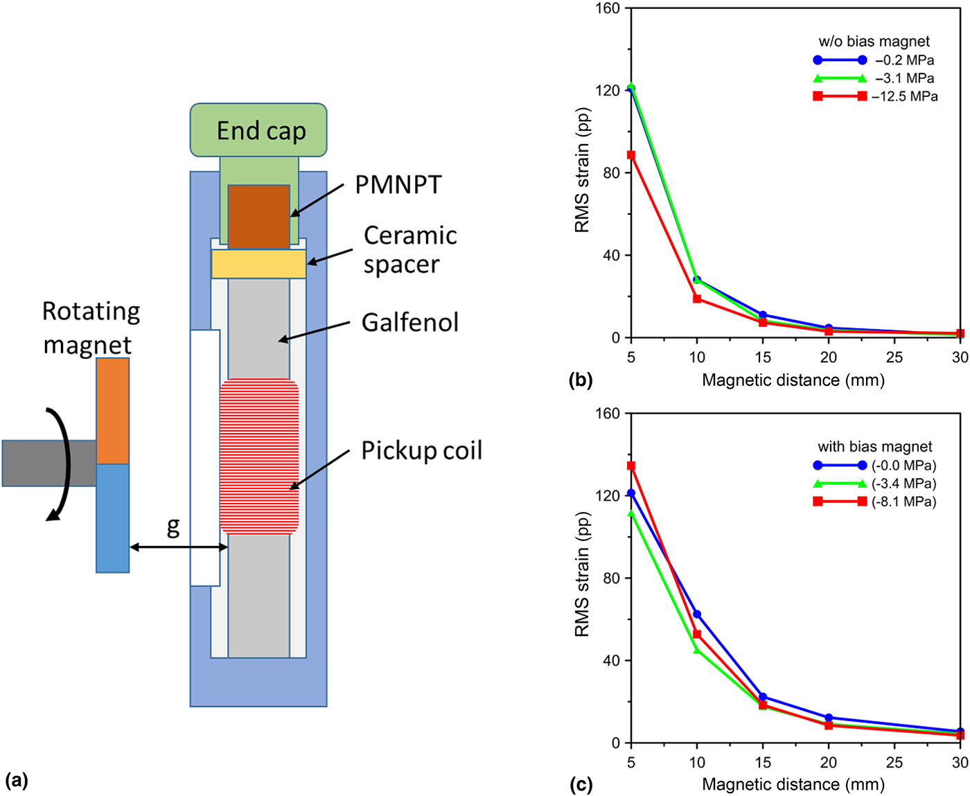
To test the energy harvester using a rotational magnet, a test setup was designed as shown in Fig. 4(a). The total strain and change in flux were directly measured as the permanent magnet was rotated slowly, and this was repeated with and without a small bias magnetic field and at several values of static compressive stress applied to the Galfenol. The distance between the magnet and the test fixture was also allowed to vary. The largest variation in strain or flux was observed with the smallest gap distance (g = 5 mm) for all conditions tested. The addition of two small permanent magnets to provide a DC bias field had a significant impact on the strain profile, and increased the total achievable strain values for similar pre-stress conditions. While this is not unexpected given the strongly non-linear magnetostriction curve of Galfenol, as discussed previously, what is particularly interesting is that the total change in strain decreases less from g = 5 to 10 mm when in the presence of a bias field – by roughly 50%–60% compared with over 75% decrease at zero-bias field. One challenge of this system is the proximity of the magnetic Galfenol to the rotating permanent magnet; this provides a resistance to the rotation, similar to a magnetic braking force, that increases the total force (or acceleration) needed to turn the magnet and consequently produce the necessary strain. Therefore, in addition to maximizing the achievable strain, the potential for operating at an increased distance with a stronger DC bias field will assist in overcoming this braking force and reducing the level of external excitation required to induce the phase transition in the relaxor ferroelectric crystal.
(a) The test fixture used for validation of the model. The recorded strain values in the Galfenol as the magnet is rotated by 180° at various distances and at several mechanical pre-stress values (b) without and (c) with a bias magnetic field.

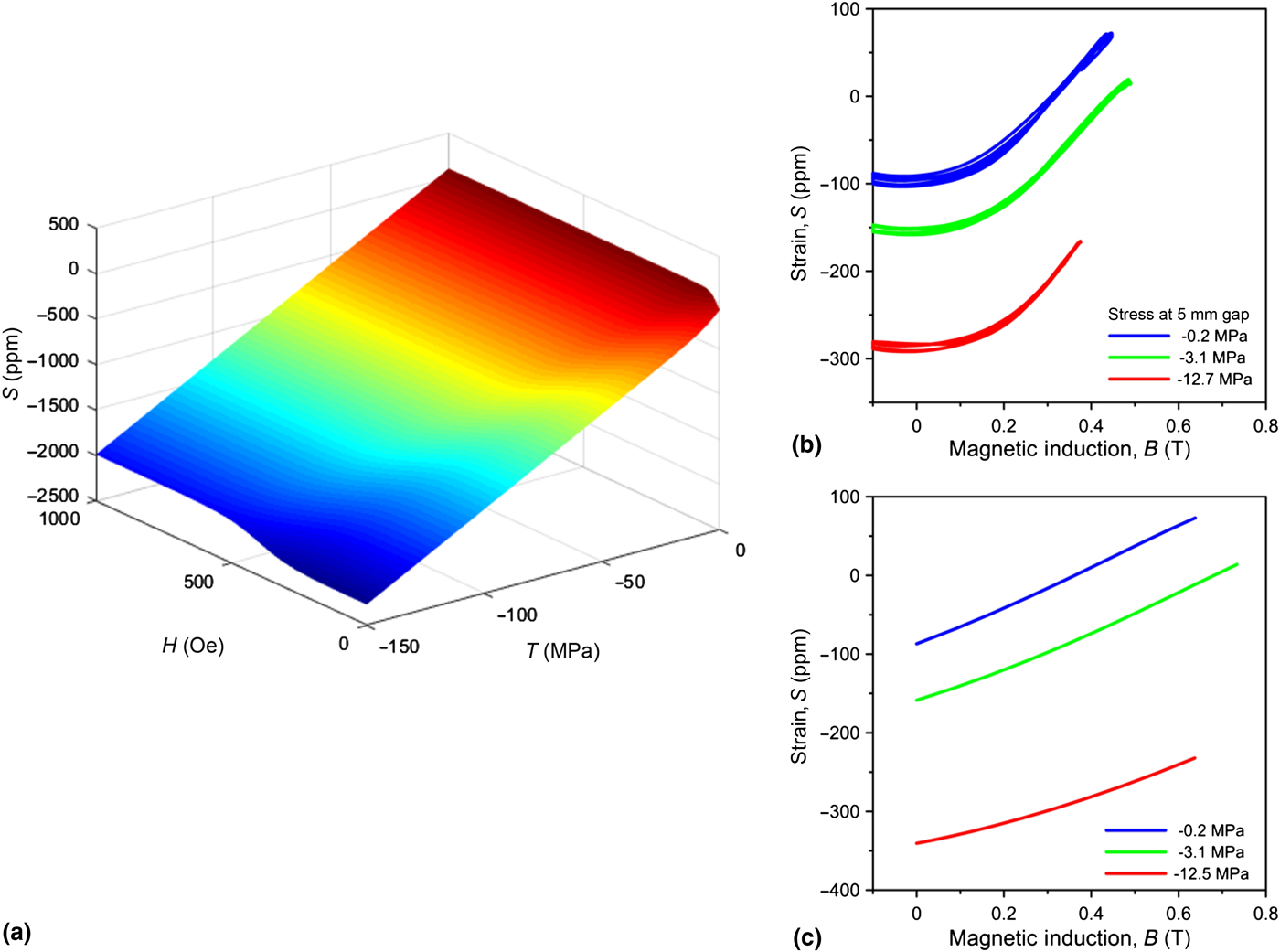
The 2D FEA model was coupled with an experimentally determined stress, strain, and field model to predict the performance of the magnetostrictor with a rotating permanent magnet. Figure 5(a) shows a nonlinear magnetostrictive material strain response model as functions of the magnetic field and the compressional stress. Figure 5(b) shows the experimental strain measurement during an external magnet rotation for various initial pre-stresses and permanent magnet distance from the Galfenol rod. The simulation results based on the model in Fig. 5(a) are shown in Fig. 5(c). In this simulation, the strain was calculated from the measured pre-stress and simulated magnetic field from FEM results. Comparing Figs. 5(b) and 5(c), the maximum strains agree well with each other, but the magnetic induction values show clear differences. This is thought to be primarily due to a difference in boundary conditions between the simulation and the test. As the Galfenol is elongated with applied magnetic field in the energy harvesting fixture, the change in length will be partially opposed by the piezocrystal, which will increase the stress and therefore decrease the magnetic flux density. However, overall the comparison of these results shows that the model will give valid strain values that confirms that the design of the prototype device will provide sufficient stroke to induce the phase transformation in the piezocrystal to produce several milliwatts of power as observed previously in such a hybrid ME system.[Reference Finkel, Pérez Moyet, Wun-Fogle, Restorff, Kosior, Staruch, Stace and Amin15] It should also be noted that the strain generated by the Galfenol was stable over many trials, and we have previously demonstrated that the phase transition in the piezocrystal has been shown to have no fatigue over 40 million cycles.[Reference Finkel, Staruch, Amin, Ahart and Lofland24] Thus, high repeatability of the generated voltage over many cycles is expected for the present design.
(a) The nonlinear magnetostrictive strain response model showing the strain when varying magnetic field and stress values. (b) The experimental strain with magnet rotation and (c) the strain results of the simulation for the experimental values of stress and the modeled magnetic field.

Work is ongoing to reduce friction in the unbalanced pendulum, and to then quantify what minimum input vibrational energy is required to rotate the magnet and induce the phase transformation. In addition to this particular excitation design, achieving the necessary AC magnetic field by fixing a magnet to a rotating motor or any oscillating component could additionally be considered. Further, based on the results of this study and the critical magnetic field needed to optimize the strain response of the Galfenol, it is also possible to utilize this harvester in proximity to some permanent magnet synchronous motors (if housed within the shielding) or to power lines carrying ~100 A, without requiring the rotating permanent magnet.
Conclusions
In summary, by using an induced rhombohedral to orthorhombic phase transition in PIN-PMN-PT single crystals, a vibrational energy harvester can operate in a non-resonant mode for broad band energy conversion. A changing magnetic field due to the motion of a permanent magnet can be used to induce the phase transition with the addition of a magnetostrictive material. 2D FEA was used to optimize the effects of the permanent magnet on the FeGa rod. The static pre-stress and bias field were highlighted as important design parameters to control. The ability to use rotational motion as well as linear displacement to achieve the necessary strain, as shown through our validated model, could allow for more flexibility in the range of motions that can be used for energy harvesting.
Acknowledgments
Funding for this project was provided by the Office of Naval Research (ONR). JY and NJ would like to thank Lauren Evoy for her assistance in measuring the Galfenol response with a rotating permanent magnet.