1. Introduction
In recent years, applications for serial industrial manipulators have spread to more advanced manufacturing processes that go far beyond the conventional pick-and-place tasks. Machining, friction-stir-welding, and even precise assembly processes from sectors like the aerospace manufacturing industry require robotic systems with a higher level of positional accuracy [Reference Villani, Suterio, Trabasso, Furtado, Alvarado and Amorim1–Reference Mei and Maropoulos4]. However, these new trends pose a well-known challenge to the typical stiffness behavior of the commercial-off-the-shelf robots [Reference Posada, Schneider, Pidan, Geravand, Stelzer and Verl5].
Measurement-assisted robotized processes that deal with online positional error compensation through the external measurement of the robot’s end-effector position are still the most effective approach for that, being able to compensate for all the robot inaccuracy sources [Reference Mei and Maropoulos4, Reference Mosqueira, Apetz, Santos, Villani, Suterio and Trabasso6, Reference Trabasso and Mosqueira7]. However, it may also represent a rather expensive solution and even limited in some situations, as, for instance, in the precise aircraft structural assembly with restricted access within the product, for example, the internal wing-box structural assembly [Reference Jamshidi, Kayani, Iravani, Maropoulos and Summers8, Reference Kayani and Jamshidi9]. Other technical possibility to deal with this problem is to install external encoders on the robot joints that can be further integrated to the robot controller [Reference Klimchik and Pashkevich10], although its current use is restricted due to intellectual property issues [Reference Devlieg11, Reference Devlieg12].
A model-based error compensation technique can be used in an automated process to control the robot motion both online and offline [Reference De Backer, Christiansson, Oqueka and Bolmsjö13–Reference Bu, Liao, Tian, Zhang and Zhang15]. In practical terms, however, since the end-user is rarely able to change the parameters of the models embedded into the robot controller, this approach must be implemented externally, over its setpoint source [Reference Reinl, Friedmann, Bauer, Pischan, Abele and Von Stryk16–Reference Roesch18]. Moreover, considering most processes face the challenge of achieving a precise positioning of the robot end-effector when a significant external wrench is acting on it, it is often necessary to define an accurate stiffness model of the manipulator [Reference Wu, Klimchik, Caro and Pashkevich19]. It is worth mentioning that compliance deviations may respond in these situations for up to 80% of the manipulator’s positional errors [Reference Bu, Liao, Tian, Zhang and Zhang15, Reference Dumas, Caro, Garnier and Furet20].
In the field of robotics, there exists several techniques that allow the user to characterize the stiffness behavior of different robots, being worth to emphasize herein the so-called elastostatic methods. [Reference Alici and Shirinzadeh21–Reference Klimchik, Pashkevich and Chablat26] They favor the application in the industrial environment, since the identification of their parameters and even their final integration can be defined externally to the robot controller (e.g. no joint torques are needed), which, as aforementioned, may be inaccessible to the end-user.
Furthermore, considering the diverse possibilities for online model-based compliance error compensation, less computationally intensive elastostatic techniques have been explored [Reference Alici and Shirinzadeh21, Reference Klimchik, Caro, Wu, Chablat, Furet, Pashkevich, Thomas and Pérez Gracia25, Reference Klimchik, Pashkevich and Chablat26]. Particularly, the lumped virtual joint method (VJM), used throughout this paper, provides a reasonable trade-off between the model accuracy and computational cost. It is based on the extension of the traditional rigid model by adding some virtual joints (localized springs) that describe the elastic deformations of the links or joints [Reference Pashkevich, Klimchik and Chablat23, Reference Klimchik, Caro, Wu, Chablat, Furet, Pashkevich, Thomas and Pérez Gracia25]. Under the assumption of a good calibration procedure, a VJM model that considers the joint and link elastic behavior would be able to compensate up to 95% of the compliance deviations [Reference Klimchik and Pashkevich27].
One of the most critical and challenging aspects to achieve an accurate stiffness model of a robotic arm is its identification, which can be viewed as a phase within the classical calibration process that embraces the tuning of the model parameters by means of an optimization approach over some experimental dataset [Reference Wu, Klimchik, Caro and Pashkevich19–Reference Alici and Shirinzadeh21, Reference Klimchik, Wu, Caro, Furet and Pashkevich24].
It is worth pointing out that, in the extensive literature of robotics, geometric and dynamic identification of robots have been comprehensively discussed [Reference Calafiore, Indri and Bona28–Reference Wu, Klimchik, Caro, Furet and Pashkevich33]. Considering the problem of the elastostatic model identification, relevant advances have been achieved over the last 10 years [Reference Wu, Klimchik, Caro and Pashkevich19, Reference Dumas, Caro, Garnier and Furet20, Reference Klimchik, Wu, Caro, Furet and Pashkevich24, Reference Klimchik, Wu, Pashkevich, Caro and Furet34–Reference Klimchik, Furet, Caro and Pashkevich36]. Assuming that it must be carried out using data describing end-effector deflections caused by external force/torque, Klimchik et al. [Reference Klimchik, Wu, Caro, Furet and Pashkevich24, Reference Klimchik, Wu, Pashkevich, Caro and Furet34] presented optimal criteria to select robot poses to improve identification accuracy. It is worth mentioning that a more complex model that accounts for the link and joint elasticities might often include redundant and relatively small elastostatic parameters, being quite sensible to the measurement noise [Reference Klimchik, Furet, Caro and Pashkevich36].
As for the geometric and dynamic modeling, the identification of a lumped elastostatic model is inherently sensitive to the parametrization, which, ideally, should be complete and without redundant parameters to avoid numerical problems [Reference Klimchik, Caro and Pashkevich35]. Effective approaches have been used when only the elasticity of the actuated joints is considered (irreducible model) [Reference Dumas, Caro, Garnier and Furet20]. However, a VJM model describing both the joint and link elasticities yields to an identification problem of a huge set of elastostatic parameters that can easily lead to failure the main numerical optimization routines [Reference Klimchik, Furet, Caro and Pashkevich36]. Additionally, even when some method leads to a feasible numerical solution, it may impair the underlying conservative nature of the stiffness modeling, making the elastostatic identification a difficult problem to be solved. This specific subject is considered in this work by a proposition of a novel parametric optimization phase that can be used within the traditional stiffness identification framework.
1.1. Related work
Alternative approaches for identifying a more complex elastostatic model that describes both the joint and link elasticities have been based on CAD/FEA tools [Reference Klimchik, Pashkevich and Chablat37]. However, considering the inherent limited precision of the CAD models in relation to the real robot components, the most usual approach is still based on measurement data collecting the robot compliant deviations under a known specific loading condition [Reference Wu, Klimchik, Caro, Furet and Pashkevich33].
In addition, Klimchik et al. [Reference Klimchik, Caro and Pashkevich35, Reference Klimchik, Furet, Caro and Pashkevich36] showed that, even when applying the concept of irreducible models with the relevant algebraical tools from the dynamic/geometric problem [Reference Khalil and Gautier32], the results obtained with the reduced model may violate some fundamental physical properties of the stiffness matrices, such as positive-definiteness and symmetry, ultimately impairing the underlying conservative assumption for the model-based compliance error compensation. Considering this, the authors proposed the concept of practical identifiability with a novel heuristic reduction procedure that eliminates too small compliance parameters. Despite being a proven effective solution to the identifiability challenges, it should be mentioned the techniques presented in ref. [Reference Klimchik, Furet, Caro and Pashkevich36] require some empirical steps of algebraic manipulation, stiffness matrices templates assumptions, and heuristic considerations regarding the values of the measurement noise and the order of magnitude of some parameters.
Considering these aspects, using the concept of Gramian matrix – known from the linear algebra [Reference Horn and Johnson38] and systems theory [Reference Sun, Yu and Anderson39, Reference Bianchin and Pasqualetti40] – and its relation to the relevant properties of the stiffness matrices, this work presents an approach that attains the goal of optimal fitting to the experimental dataset while preserving the model’s conservative assumption. The method is presented as a contribution to the elastostatic identification theory, evaluated on different numerical examples extracted from refs. [Reference Klimchik, Caro and Pashkevich35, Reference Klimchik, Furet, Caro and Pashkevich36] and on real experimental data obtained for a real heavy-payload industrial manipulator.
This work is organized as follows: Section 2 presents the concepts and methods used throughout the paper, developing the robot VJM model and reviewing the positive-definiteness and the symmetry properties for the stiffness matrices and their relation to the Gramian matrix; Section 3 details the classical elastostatic identification problem; Section 4 presents the developed method; numerical examples are presented in Section 5; Section 6 brings experimental analyses; the benefits and limitations of the proposed method are detailed in Section 7; Section 8 concludes the work.
2. Concepts and methods
2.1. Manipulator stiffness modeling
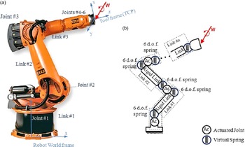
A typical serial articulated robot is depicted in Fig. 1(a) and its generic elastostatic architecture (Fig. 1(b)) is comprised of a fixed base and a serial chain of flexible links joined by rotational flexible actuated joints and an end-effector, over which a wrench w (force/torque) is acting on.
(a) Manipulator KUKA® KR-500 L480 and (b) its complete VJM representation.

The VJM establishes that, besides the 1-d.o.f. virtual springs commonly included in the actuated joints to model the joint compliance [Reference Dumas, Caro, Garnier and Furet20], the original rigid model should be extended by adding virtual joints (localized springs with up to 6 d.o.f.) to describe the elastic deformations of the links (Fig. 1(b)) [Reference Pashkevich, Klimchik and Chablat23]. As in refs. [Reference Pashkevich22, Reference Klimchik, Furet, Caro and Pashkevich36], the equivalent extended kinematic chain is described by:
-
(i) a rigid link between the robot’s base and the first actuated joint modeled as the constant homogenous transformation matrix T Base;
-
(ii) flexible actuated joints modeled as a homogeneous matrix function
 ${\bf{T}}_{{\rm{Joint}}}^i\left( {{q^i} + \theta _{Ac}^i} \right)$
, which depends on the actuated joint variable q
i
and the virtual joint variable
$\theta _{Ac}^i$
that takes into account the joint compliance;
-
(iii) a set of rigid links, described by the constant homogenous transformation matrices
${\bf{T}}_{{\rm{Link}}}^i$
; -
(iv) a set of 6-d.o.f. virtual joints which model the link flexibility and are described by the homogeneous matrix function
${{\bf{T}}_{{\rm{VJM}}}}\left( {{\boldsymbol{\theta }}_{{\bf{Link}}}^{\bf{i}}} \right)$
, which depends on the virtual joint variables
${\boldsymbol{\theta }}_{{\bf{Link}}}^{\bf{i}} = \left( {\theta _x^i,\theta _y^i,\theta _z^i,\theta _{\varphi x}^i,\theta _{\varphi y}^i,\theta _{\varphi z}^i} \right)$
corresponding to the translation/rotation deflections in/around the axis x, y, z; -
(v) a rigid link from the last joint to the end-effector, modeled as a constant homogenous matrix transformation T Tool.


The final robot pose is modeled by the homogeneous transformation T shown in Eq. (1), which defines the end-effector location subject to the variations of all joint coordinates (virtual and actuated joints) [Reference Klimchik, Furet, Caro and Pashkevich36]:
 \begin{align}{\bf{T}} = {{\bf{T}}_{{\rm{Base}}}} \cdot \left[ {\prod \nolimits_{i = 1}^n {\bf{T}}_{{\rm{Joint}}}^i\left( {{q^i} + \theta _{{\rm{Ac}}}^i} \right) \cdot {{\bf{T}}_{{\rm{Link}}}} \cdot {{\bf{T}}_{{\rm{VJM}}}}\left( {\theta _{{\rm{Link}}}^i} \right)} \right] \cdot {{\bf{T}}_{{\rm{Tool}}}}\end{align}
where n is the number of links/joints (6, in the present case). For the sake of simplification, the rotation and translation components can be extracted from the homogeneous matrix T [Reference Craig41], so that the equivalent geometric model can be rewritten as shown in Eq. (2).
 \begin{align}{\bf{X}} = {\bf{g}}\left( {{\bf{q}},{\rm{\;}}{\boldsymbol{\theta }}} \right)\end{align}
where g(
 $ \cdot $
) denotes a relevant vector function and the vector X = (p,
 $\boldsymbol{\varphi}$
)
T
defines both the end-effector tool frame position p = (x, y, z)
T
and orientation
 $\boldsymbol{\varphi}$
= (
 ${\varphi}$
x
,
 ${\varphi}$
y
,
 ${\varphi}$
z
)
T
in relation to the robot world frame. The vector q = (q
1
, q
2
, …,q
n
)
T
is composed by all actuated coordinates defined by the robot controller, whereas the vector
 $\boldsymbol{\theta}$
= (
 ${{\boldsymbol{\theta }}_1}$
,
 ${{\boldsymbol{\theta }}_2}$
, …,
 ${{\boldsymbol{\theta }}_{n\theta }}$
)
T
consists of all virtual joint coordinates from all the n
θ
virtual joints whose values are dependent on the external loading/wrench applied to the end-effector.
The representation of the manipulator stiffness behavior considers the end-effector displacement ΔX and the external wrench w as the input and output of the model, respectively. Thus, the manipulator stiffness equation is written as
 \begin{align}{\bf{w}} = {{\bf{K}}_{\rm{C}}} \cdot \Delta {\bf{X}}\end{align}
where K C is the manipulator Cartesian stiffness matrix for a given configuration q, subjected to the geometric constraints given in Eq. (2) [Reference Pashkevich22].
An alternative expression for the Cartesian stiffness matrix can be developed by assuming the so-called generalized Hooke’s law for the manipulator [Reference Salisbury42]. According to that, variations in the virtual joint variables
 $\boldsymbol{\theta}$
are linearly related to the virtual force/torque reactions applied to the corresponding links/joints. This means τ
θ
= K
θ
 $\cdot$
Δ
 $\boldsymbol{\theta}$
, where τ
θ
= (
 $\boldsymbol{\tau}$
θ1
,
 $\boldsymbol{\tau}$
θ2
, …,
 $\boldsymbol{\tau}$
θnθ
)
T
is the vector of the virtual joint reactions and K
θ
= diag (K
θ1
, K
θ2
, …, K
θnθ
) is the virtual spring stiffness matrix; K
θi
represents the elastostatic property of the corresponding link/joint. Moreover, assuming small arbitrary displacements of the virtual joints Δ
 $\boldsymbol{\theta}$
around the equilibrium neighborhood, the corresponding deviations of the end-effector are given by ΔX = J
θ
 $\cdot$
Δ
 $\boldsymbol{\theta}$
, where J
θ
= ∂g(q,
 $\boldsymbol{\theta}$
)/∂
 $\boldsymbol{\theta}$
is the Jacobian with respect to the virtual variables
 $\boldsymbol{\theta}$
, which may be computed from Eq. (2) analytically or semi-analytically [Reference Pashkevich22, Reference Pashkevich, Klimchik and Chablat23].
Thus, applying the principle of virtual work and taking into account the previous considerations, and solving the resultant statics equations for w, it yields the so-called congruence transformation between the manipulator Cartesian stiffness matrix and the joint stiffness matrix [Reference Pashkevich, Klimchik and Chablat23],
 \begin{align}{{\bf{K}}_{\rm{C}}} = \left( {{{\bf{J}}_{\rm{\theta }}}^{ - {\rm{T}}} \cdot {{\bf{K}}_{\rm{\theta }}} \cdot {{\bf{J}}_{\rm{\theta }}}^{ - 1}} \right)\end{align}
The reciprocal relation describing a better manipulator compliance behavior results from Eqs. (3) and (4), assuming the external wrench w and the end-effector displacement ΔX as the input and output of the model, respectively, yielding
 \begin{align}\Delta {\bf{X}} = {\bf{C}} \cdot {\bf{w}}\end{align}
 \begin{align}{\bf{C}} = \left( {{{\bf{J}}_{\rm{\theta }}} \cdot {{\bf{C}}_{\rm{\theta }}} \cdot {{\bf{J}}_{\rm{\theta }}}^T} \right)\end{align}
where C = K C –1 is the aggregated Cartesian compliance matrix for a given configuration q and C θ = K θ –1 is the aggregated joint compliance matrix of the manipulator. Since the matrices {K θi , i = 1, 2, …, n θ } (or their reciprocal joint compliance matrices {C θi =(K θi )–1, i = 1, 2, …, n θ }) are usually unknown, in order to calculate Eq. (4), they must be identified [Reference Klimchik, Furet, Caro and Pashkevich36]. This is addressed in Sections 3 and 4. In the sequence, some relevant physical and mathematical aspects related to the elastostatic models are reviewed.
2.2. Properties of the elastostatic model
The stiffness model given by Eq. (4) is based upon the following conservative assumption from the elasticity theory: (i) the force due to the stiffness matrix is integrable and conservative and (ii) the work done by this force is conservative, that is, it depends only on the initial/end potential energy states [Reference Timoshenko and Goodier43].
While the joint stiffness matrix K θ can be manually prescribed in relation to the conservative nature of the stiffness modeling, Chen and Kao [Reference Chen and Kao44] demonstrated that Eq. (4) for computing K C is only valid at the unloaded equilibrium configuration; otherwise, the compliance error compensation violates the conservative properties. They showed that it is a special case of the conservative congruence transformation, written as
 \begin{align}{{\bf{K}}_{\rm{C}}} = {\bf J_\theta }^{ - T} \cdot \left( {{{\bf{K}}_\theta } - {{\bf{K}}_w}} \right) \cdot {{\bf{J}}_\theta }^{ - 1}\end{align}
where K
w
= ∂2 [g
T
(q,
 $\boldsymbol{\theta}$
)w]/∂
 $\boldsymbol{\theta}^{2}$
is a Hessian-derivative term that accounts for the incremental changes in the robot arm geometry due to the application of the external wrench. Despite of not being practical for identification purposes, Eq. (7) evinces that, while applying Eq. (3), the robot stiffness behavior is non-linear in relation to w.
Numerically and more practically, an n
 $ \times $
n stiffness (or compliance) matrix K is said to be conservative if it is (i) symmetric (k
ij
= k
ji
) and (ii) positive-definite, where k
ij
is the (i, j)-th element of K [Reference Chen and Kao44–Reference Kao and Ngo46]. Moreover, a definition and an equivalent assertion (whose proof is omitted herein) may apply for the positive-definiteness of a matrix [Reference Horn and Johnson38]:
Definition 1. A symmetric matrix
 $\textbf{K} \in {\mathbb{R}^{n \times n}}$
is positive-definite if
u
T
.K.u
> 0 for any not null vector
u
 $ \in {\mathbb{R}^{n \times 1}}$
. It is positive semi-definite if
u
T
.K.u
≥ 0.
Assertion 1.
A symmetric matrix
 $\textbf{K} \in {\mathbb{R}^{n \times n}}$
is positive-definite if all its eigenvalues are > 0. It is positive semi-definite if at least one of its eigenvalues is zero and the others are > 0.
These properties are extremely important to be considered for both the Cartesian (K C) and the joint (K θ ) stiffness matrices. In special, even though K θ is supposed to be a fixed elastostatic property of the manipulator’s mechanical components, it is usual for an inattentive identification process to produce a viable numerical solution that violates positive-definiteness or symmetry [Reference Klimchik, Caro and Pashkevich35]. Considering this, a useful mathematical property of the stiffness matrices is presented in the next subsection.
2.3. Gramian nature of the stiffness matrices
Definition of the Gramian matrix, named after his author Jörgen Pedersen Gram (1850–1916) [Reference Horn and Johnson38]:
Definition 3. Given an n-dimensional set of
 $ m\times 1$
vectors
 $\{{{\bf{v}}_j} \in {\bf{V}},\ j=1,\cdots,n\}$
, where V is a vector space in
 ${\mathbb{R}^m}$
with an inner product
 $<\cdot>$
, the Gramian matrix G of this set is the
 $ n\times n $
symmetric matrix whose entries aij
are the inner products <v
i
 $\cdot$
v
j>, that is,
 ${\bf{G}} = \left[ \langle{{{\bf{v}}_i},{{\bf{v}}_j}}\rangle \right] \in {\mathbb{R}^{n \times n}}$
.
Several engineering fields use this definition, among them, the systems theory [Reference Sun, Yu and Anderson39, Reference Bianchin and Pasqualetti40]. In the framework of the lumped elastostatic stiffness modeling, the following theorem applies directly to the method proposed herein:
Theorem 1.
A symmetric matrix
 ${\bf{G}} \in {\mathbb{R}^{n \times n}}$
is positive semi-definite if and only if it is the Gramian matrix of some n-dimensional set of vectors {
 $\{{{\bf{v}}_j} \in {\bf{V}}, j =1,\cdots,n\}$
, where V is a vector space in
 $\mathbb{R}^{m}$
with an inner product
 $<\cdot>$
.
Since the symmetry of G is straightforwardly derived from Definition 3 and the commutativity of the inner product, the proof for the equivalence to the positive semi-definiteness is given as ref. [Reference Horn and Johnson38],
-
✓ First part: given
${\bf{G}} = \left[ \langle{{{\bf{v}}_i},{{\bf{v}}_j}}\rangle \right] \in {\mathbb{R}^{n \times n}}$
and a not null vector
$\textbf{u} \in {\mathbb{R}^{n \times 1}}$
, it follows(8)where it has been used the bi-linearity (2nd and 3rd equalities) and positive-definiteness (4th equality) of the inner product to evince the positive semi-definiteness of G.
\begin{align}{{\bf{u}}^T}{\bf{Gu}} = \mathop \sum \nolimits_{i,j} \left\langle{{\bf{v}}_i},{{\bf{v}}_j}\right\rangle{{\rm{u}}_i}{{\rm{u}}_j} = \mathop \sum \nolimits_{i,j} \left\langle{{\bf{v}}_i}{{\rm{u}}_i},{{\bf{v}}_j}{{\rm{u}}_j}\right\rangle = \left\langle\mathop \sum \nolimits_i {{\bf{v}}_i}{{\rm{u}}_i},\mathop \sum \nolimits_j {{\bf{v}}_j}{{\rm{u}}_j}\right\rangle = \left\|\mathop \sum \nolimits_i {{\bf{v}}_i}{{\rm{u}}_i}^2 \ge 0\right\|\end{align}
-
✓ Second part: given that G is symmetric and positive semi-definite


 \begin{align}{\bf{G}} = {\bf{RD}}{{\bf{R}}^{\textrm{T}}} = {\bf{R}}\left( {\sqrt {\bf{D}} {{\sqrt {\bf{D}} }^{\textrm{T}}}} \right){{\bf{R}}^{\textrm{T}}} = \left( {{\bf{R}}\sqrt {\bf{D}} } \right){\left( {{\bf{R}}\sqrt {\bf{D}} } \right)^{\textrm{T}}}\therefore {\bf{G}}\;{\rm{is\;the\;gramian\;of\;the\;}}{\bf{R}}\sqrt {\bf{D}} {\rm{\;rows}}\end{align}
because of the matrix spectral decomposition. A corollary (whose proof is found in ref. [Reference Horn and Johnson38]) from Theorem 1 regarding the positive-definite aspect is:
Corollary 1.
G is positive-definite if and only if the vectors {
 ${{\bf{v}}_i}$
} are linearly independent.
Theorem 1 implies that every conservative n
 $ \times $
n stiffness matrix is the Gramian matrix of some set of vectors or, equivalently and more usefully, that there should exist some n-dimensional set of vectors
 $\{{{\bf{v}}_j} \in {\mathbb{R}^m}\}$
able to generate it. This is used in this work to propose a novel identification method for C
θ
(and reciprocally K
θ
).
3. Elastostatic parameter identification – the classical approach
Based on Klimchik et al. [Reference Klimchik, Caro and Pashkevich35], the problem of estimating the individual compliance matrices
 $\{\textbf{C}_{\theta},i=1,2,\ldots,n_{\theta}\}$
can be solved by rearranging Eq. (5)–(6) as
 \begin{align}\Delta {\bf{X}} = \sum \nolimits_{i = 1}^{{n_\theta }} \left( {{{\bf{J}}_\theta }^{\left( i \right)} \cdot {{\bf{C}}_{\theta i}} \cdot {{\bf{J}}_\theta }{{^{\left( i \right)}}^T}} \right) \cdot {\bf{w}}\end{align}
where the matrices {J
θ
(i)} are the corresponding sub-Jacobians obtained by the fractioning of the full Jacobian J
θ
T
= [
 ${{\bf{J}}_{\theta} }^{{(1)}^T},\;\;{{\bf{J}}_{\theta} }^{{(2)}^T},\;\; \ldots \;$
]
T
[Reference Klimchik, Caro and Pashkevich35]. Thus, upon some mathematical manipulations and gathering all the necessary parameters (elements of the matrices C
θi
, i= 1, 2, …) into the single optimization vector
 ${\boldsymbol{\pi }} = \left( {{c_{\theta {1_{11}}}},{c_{\theta {1_{12}}}}, \cdots ,{c_{\theta {n_{66}}}}} \right)$
, it yields to
 \begin{align}\Delta {\bf{X}} = {\bf{A}}\left( {{\bf{q}},{\bf{w}}|{\boldsymbol{\pi }}} \right) \cdot {\boldsymbol{\pi }}\end{align}
where
 \begin{align}{\bf{A}}\left( {{\bf{q}},{\bf{w}}|{\boldsymbol{\pi }}} \right) = \left[ {{{\bf{J}}_1}{{\bf{J}}_1}^T{\bf{w}},\;\;{{\bf{J}}_1}{{\bf{J}}_2}^T{\bf{w}}, \ldots ,{{\bf{J}}_k}{{\bf{J}}_k}^T{\bf{w}}} \right]\end{align}
is the observation matrix that defines the mapping between the unknown compliances
 $\boldsymbol{\pi} $
and the end-effector displacements ΔX under the loading w for the configuration q; the vectors J
i
represent the columns of each J
θ
(i) [Reference Klimchik, Caro and Pashkevich35]. Equation (11) can be further manipulated to embrace the calibration experiments that are carried out for N different configurations of the manipulator defined by the actuated joint coordinates
 ${{\bf{q}}_u},{\rm{\;\;}}u = 1, \ldots $
N, given by Eq. (13), a system of linear equations that can be used for the identification
 \begin{align}\Delta {{\bf{X}}_u} = {\bf{A}}\left( {{{\bf{q}}_u},{{\bf{w}}_u}|{\boldsymbol{\pi }}} \right) \cdot {\boldsymbol{\pi }} + {{\boldsymbol{\varepsilon }}_u}\;,\;u = 1, \ldots N\end{align}
where
 $\boldsymbol{\varepsilon}$
u denotes the vector of measurement errors [Reference Klimchik, Caro and Pashkevich35]. The identification is then translated into an optimization problem defined over the experimental dataset {q
u, w
u|ΔX
u,
 $u = 1, \ldots N$
}
 \begin{align}\min\limits_{\boldsymbol{\pi}}\left\{ {F = \sum \nolimits_{\rm u = 1}^{\rm N} {{\left[ {{{\bf{A}}_{\pi \textrm{u}}} \cdot {\boldsymbol{\pi }} - \Delta {{\bf{X}}_{\textrm{u}}}} \right]}^T} \cdot {{\boldsymbol{\eta }}^T} \cdot {\boldsymbol{\eta }} \cdot \left[ {{{\bf{A}}_{\pi \textrm{u}}} \cdot {\boldsymbol{\pi }} - \Delta {{\bf{X}}_{\textrm{u}}}} \right]} \right\}\end{align}
where
 ${{\bf{A}}_{\pi u}} = {\bf{A}}\left( {{{\bf{q}}_u},{{\bf{w}}_u}|{\boldsymbol{\pi }}} \right)$
and
 $\boldsymbol{\eta}$
is the matrix of weighting coefficients that can be chosen to normalize the error data and homogenize the least-squares cost function (Eq. (14)), which sums together translation and orientation error components with different magnitudes and units [Reference Klimchik, Caro and Pashkevich35]. From Eq. (14), the weighted linear least-squares technique can be used to derive the following solution:
 \begin{align}\hat{\boldsymbol\pi} = {\left( {\mathop \sum \nolimits_{{\rm{u}} = 1}^{\rm{N}} {{\bf{A}}_{{\rm{\pi u}}}}^{\rm{T}} \cdot {\boldsymbol{\eta} ^{\rm{T}}} \cdot \boldsymbol{\eta} \cdot {{\bf{A}}_{{\rm{\pi u}}}}} \right)^{ - 1}} \cdot \left( {\mathop \sum \nolimits_{{\rm{u}} = 1}^{\rm{N}} {{\bf{A}}_{{\rm{\pi u}}}}^{\rm{T}} \cdot {\boldsymbol{\eta} ^{\rm{T}}} \cdot \boldsymbol{\eta} \cdot \Delta {{\bf{X}}_{\rm{u}}}} \right)\end{align}
Equation (15) represents the classical weighted least-squares solution, which is the most used approach for the elastostatic identification [Reference Klimchik, Caro, Wu, Chablat, Furet, Pashkevich, Thomas and Pérez Gracia25, Reference Klimchik, Caro and Pashkevich35, Reference Klimchik, Furet, Caro and Pashkevich36, Reference Wu47]. However, it is well-known that the accuracy of the least-squares estimate is rather sensitive to the inversion feasibility of
 $\;\;\left( {\mathop \sum \nolimits_{u = 1}^N {{\bf{A}}_{\pi u}}^T{{\boldsymbol{\eta }}^T}{\boldsymbol{\eta }}{{\bf{A}}_{{\rm{\pi }}u}}} \right)$
, named information matrix [Reference Rice48]. Furthermore, Klimchik et al. [Reference Klimchik, Furet, Caro and Pashkevich36] showed that even when the information matrix is full-rank, the measurement noise may yield to a counterintuitive numerical result. To deal with this, the next section details an alternative non-linear optimization process for the elastostatic identification of industrial manipulators based upon the Gramian nature of the stiffness matrices (see Section 2.3).
4. Gramian-constrained optimization: A novel approach
4.1. Basic assumptions and definitions
Let us assume that, according to Theorem 1, there should exist an n-dimensional set of vectors {
 ${\bf{v}}_j^{\left( i \right)} \in {R^m},\;j = 1,\; \ldots ,\;n$
} able to generate each of the i-th n×n conservative compliance matrices {C
θi
= (K
θi
)–1 , i = 1, 2, …n
θ
}. Then, according to the Definition 3
 \begin{align}{{\bf{C}}_{\theta i}} = gramian\left( {{\bf{v}}_1^{\left( i \right)},{\bf{v}}_2^{\left( i \right)}, \ldots ,{\bf{v}}_n^{\left( i \right)}} \right)\end{align}
where the operator ‘gramian’ denotes the Gramian matrix generated over the i-th set {
 ${\bf{v}}_j^{\left( i \right)} \in {R^m},\;j = 1,\; \ldots ,\;n$
}. By rearranging Eq. (5)–(6) together and assuming that all the vectors from all the sets (the desired parameters in this case) can be collected together into the single (
 $n\cdot m\cdot n$
θ
)
 $ \times $
1 optimization vector b = [
 ${\bf{v}}_1^{\left( 1 \right)};{\bf{v}}_2^{\left( 1 \right)}; \ldots ;{\bf{v}}_n^{\left( {{n_\theta }} \right)}$
], and further adapting the related equations for the N dataset points {q
u, w
u |ΔX
u,
 $u = 1, \ldots N$
},
 \begin{align}\Delta {{\bf{X}}_u}\left( {{{\bf{q}}_u},{{\bf{w}}_u}{\rm{|}}{\bf{b}}} \right) = \left[ {{{\bf{J}}_\theta } \cdot {{\bf{C}}_\theta }\left( {\bf{b}} \right) \cdot {{\bf{J}}_\theta }^T} \right] \cdot {{\bf{w}}_u} + {{\boldsymbol{\varepsilon }}_u}\;\;,\;\;u = 1, \ldots N\end{align}
where
 $\boldsymbol{\varepsilon}$
u still denotes the vector of measurement errors. It has been made clear that C
θ
(b) = diag (C
θ1
, C
θ2
, …, C
θnθ
) represents a non-linear mapping between the aggregated joint compliance matrix and the parameter optimization vector b according to Eq. (16). A convenient error vector can be derived for each u-th equation as
 \begin{align}{{\bf{e}}_u}\left( {{{\bf{q}}_{\rm{u}}},{{\bf{w}}_{\rm{u}}}{\rm{|}}{\bf{b}}} \right) = \Delta {{\bf{X}}_{\rm{u}}} - \left[ {{{\bf{J}}_{\rm{\theta }}}\left( {{{\bf{q}}_{\rm{u}}}} \right) \cdot {{\bf{C}}_{\rm{\theta }}}\left( {\bf{b}} \right) \cdot {{\bf{J}}_{\rm{\theta }}}{{\left( {{{\bf{q}}_{\rm{u}}}} \right)}^{\rm{T}}}} \right] \cdot {{\bf{w}}_{\rm{u}}}\;\;,\;\;{\rm{u}} = 1, \ldots {\rm{N}}\end{align}
where the error vector e
u = [δΔx
u, δΔy
u, δΔz
u, δΔ
 ${\varphi}$
xu, δΔ
 ${\varphi}$
yu, δΔ
 ${\varphi}$
zu]T stands for the accomplished error (δ) in the estimate of the end-effector deviation ΔX
u. Departing from this, the identification can be translated into a non-linear minimization problem defined over whole measurement dataset {q
u, w
u|ΔX
u,
 ${\rm{u}} = 1, \ldots {\rm{N}}$
} as
 \begin{align}\min_{\bf b}\left\{ {{{\rm{F}}_M} = \frac{1}{{\sqrt 2 {\sigma _p}}}\sqrt {\frac{{\mathop \sum \nolimits_{u = 1}^{\rm{N}} \left( {{\rm{\delta \Delta }}{x_u}^2 + {\rm{\delta \Delta }}{y_u}^2 + {\rm{\delta \Delta }}{z_u}^2} \right)}}{{\rm{N}}}} + \frac{1}{{\sqrt 2 {\sigma _\varphi }}}\sqrt {\frac{{\mathop \sum \nolimits_{u = 1}^{\rm{N}} \left( {{\rm{\delta \Delta }}{{\rm{\varphi }}_{xu}}^2 + {\rm{\delta \Delta }}{{\rm{\varphi }}_{yu}}^2 + {\rm{\delta \Delta }}{{\rm{\varphi }}_{zu}}^2} \right)}}{{\rm{N}}}} } \right\}\end{align}
where the cost function F
M
is modified to weight differently between the translation and rotation RMS distance-based error portions by considering the measurement uncertainty: the former portion is weighted by the inverse of the position uncertainty σp, and the latter is weighted by the inverse of the orientation uncertainty σ
 $_{\varphi}$
. These quantities could be a specification from the measuring device manufacturer or empirically estimated [Reference Wu47]. Since most calibration processes require two measurements (with and without loading), these uncertainties are increased by the factor
 $\;\sqrt 2 $
[Reference Klimchik, Furet, Caro and Pashkevich36]. Besides of being a homogenized error-cost function, Eq. (19) leads to a theoretical minimum threshold limit for the optimization, namely 2. This would mean that the more the identification approaches this value, the more it is averagely close to the limit accuracy of the experimental data (
 $\sqrt 2 $
σp and
 $\sqrt 2 $
σ
 $_{\varphi}$
). Besides of being difficult to achieve, reaching a value too lower than 2 would imply on the possibility of the model getting biased by the noise. Therefore, it is enough to solve Eq. (19) for an objective limit slightly higher or close to 2.
4.2. Gramian-constrained optimization process
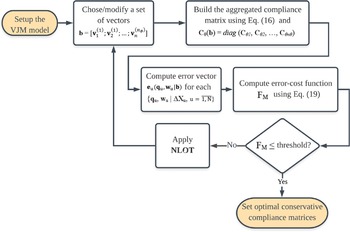
Under the light of the aforementioned definitions, Fig. 2 depicts the Gramian-constrained optimization (GCO) process for the stiffness model identification of industrial manipulators that is proposed herein.
Gramian-constrained optimization process for the manipulator stiffness model identification.

It should be stressed from Fig. 2 that the very beginning step of this process is the proper selection and parametrization of the VJM model, which means that at least some physical model reduction considerations should be applied prior to the GCO-based identification. Even though the technique proposed herein will inherently lead to a symmetric conservative compliance matrix, the application of some reduction steps to simplify the model could help to avoid convergence problems. For instance, the actuated joint compliances before which there is an elastic link should be eliminated from the set of model parameters and included in the compliance matrix of the previous link, a physical reduction step called aggregation [Reference Klimchik, Caro and Pashkevich35]. Moreover, some heavy-payload robots present some quite rigid links (comparatively to the others) and its compliances could be firstly disregarded. These simple considerations may help to reach a solution that is numerically and physically meaningful due to the Gramian constraint.
The remaining of the proposed approach is comprised of, using some relevant non-linear optimization technique (NLOT), iteratively changing the optimization vector b = [
 ${\bf{v}}_1^{\left( 1 \right)};{\bf{v}}_2^{\left( 1 \right)}; \ldots ;{\bf{v}}_n^{\left( {{n_\theta }} \right)}$
] until the desired threshold for F
M
is reached. Some hybrid NLOT that applies heuristic/stochastic and deterministic methods may lead to more effective results. In this work, a genetic algorithm [Reference Goldberg49] is used to get the best initial guess b
0, from which the pseudo-deterministic Global Search algorithm [Reference Ugray, Lasdon, Plummer, Glover, Kelly and Marti50] finds the optimal result b
*, both from the Optimization Toolbox of the Matlab® 2019b. The final compliance matrices are obtained from Eq. (16).
4.3. Order of the vector space
For all the n×n conservative compliance matrices C
θi
, (n.m.n
θ
) parameters should be determined within the vector b. A guidance to select the order m of the vector space
 ${\bf{V}} \subset {\mathbb{R}^m}$
from which the vectors
 ${\bf{v}}_j^{\left( i \right)}$
are taken should be useful. About 6N scalar equations can be derived from the N measurement dataset points so that an overdetermined system is on (
 $n\cdot m\cdot n$
θ
) ≤ 6N. On the other hand, considering the symmetry property, each of the n
 $ \times $
n conservative compliance matrices C
θi
presents in fact n
 $\cdot$
(n+1)/2 independent parameters. Thus, reasonably (
 $n\cdot m$
) ≥ (1+ n)
 $\cdot$
n/2, yielding to
 \begin{align}\left( {n + 1} \right)/2 \le m \le 6N/\left( {n \cdot {n_\theta }} \right)\end{align}
5. Numerical analyses
5.1. Motivation example
Let us use a numerical example extracted from ref. [Reference Klimchik, Caro and Pashkevich35] to illustrate the potential of the presented method. It is the elastostatic identification of a single link of a given robot, whose compliance matrix has been determined as
 \begin{align}C = \left[ {\begin{array}{c@{\quad}c@{\quad}c@{\quad}c@{\quad}c@{\quad}c}{4.50 \cdot {{10}^{ - 8}}}&0&0&0&0&0\\ \\[-7pt] 0&{8.01 \cdot {{10}^{ - 5}}}&0&0&0&{3.98 \cdot {{10}^{ - 4}}}\\ \\[-7pt] 0&0&{{{3.64.10}^{ - 5}}}&0&{ - 1.71 \cdot {{10}^{ - 4}}}&0\\ \\[-7pt] 0&0&0&{3.76 \cdot {{10}^{ - 3}}}&0&0\\ \\[-7pt] 0&0&{ - 1.71 \cdot {{10}^{ - 4}}}&0&{1.09 \cdot {{10}^{ - 3}}}&0\\ \\[-7pt] 0&{3.98 \cdot {{10}^{ - 4}}}&0&0&0&{2.65 \cdot {{10}^{ - 3}}}\end{array}} \right]\end{align}
In this example, this compliance matrix is estimated according to a calibration process that follows both the classical least-squares and the GCO-based approaches. As in ref. [Reference Klimchik, Caro and Pashkevich35], data are generated by means of virtual experiments, where the link is assumed to be fixed on one side while an external wrench w
u is applied to the other side; six loading conditions (N = 6) were run, limiting the force and torque magnitude by 10 N and 10 N.m, respectively; the corresponding deflection is computed as ΔX
u = C
 $\cdot$
w
u +
 $\boldsymbol{\varepsilon}$
u, where
 $\boldsymbol{\varepsilon}$
u is the measurement noise, whose magnitude has been defined as σ
p
= 25 μm for the position and as σ
 ${\varphi}_{\varphi}=0.25$
mrad for the orientation.
The obtained compliance matrices are presented in Eq. (22) and in Eq. (23) for the weighted least-squares and the GCO-based identification approaches, respectively.
 \begin{align}{C_{LS}} = \left[ {\begin{array}{c@{\quad}c@{\quad}c@{\quad}c@{\quad}c@{\quad}c} \mathbf{-7.32\cdot 10^{-7}}&-2.15\cdot 10^{-6}&2.05\cdot 10^{-6}&1.29\cdot 10^{-6}&-2.25\cdot 10^{-6}&\mathbf{-6.89\cdot 10^{-7}}\\ \\[-7pt] -1.58\cdot 10^{-6}&7.58\cdot 10^{-5}&-2.10\cdot 10^{-6}&6.52\cdot 10^{-7}&-9.35\cdot 10^{-7}&3.91\cdot 10^{-4}\\ \\[-7pt]-3.00\cdot 10^{-6}&1.79\cdot 10^{-6}&3.43\cdot 10^{-5}&-1.95\cdot 10^{-6}&-1.73\cdot 10^{-4}&1.03\cdot 10^{-6}\\ \\[-7pt] 8.39\cdot 10^{-6}&-1.74\cdot 10^{-5}&-3.59\cdot 10^{-5}&3.80\cdot 10^{-3}&-1.80\cdot 10^{-5}&2.50\cdot 10^{-5}\\ \\[-7pt] -3.16\cdot 10^{-5}&-1.19\cdot 10^{-5}&-1.79\cdot 10^{-4}&-1.72\cdot 10^{-5}&1.10\cdot 10^{-3}&1.85\cdot 10^{-5}\\ \\[-7pt] \mathbf{2.26\cdot 10^{-5}}&4.33\cdot 10^{-4}&2.66\cdot 10^{-5}&6.69\cdot 10^{-5}&3.21\cdot 10^{-5}&2.60\cdot 10^{-3} \end{array}} \right]\end{align}
 \begin{align}{C_{GCO}} = \left[ {\begin{array}{c@{\quad}c@{\quad}c@{\quad}c@{\quad}c@{\quad}c}\mathbf{1.12\cdot 10^{-7}}&-1.31\cdot 10^{-6}&3.06\cdot 10^{-7}&1.87\cdot 10^{-6}&-9.50\cdot 10^{-7}&\mathbf{5.49\cdot 10^{-7}}\\[3pt]-1.31\cdot 10^{-6}&7.62\cdot 10^{-5}&-8.24\cdot 10^{-7}&-8.45\cdot 10^{-7}&-4.65\cdot 10^{-7}&3.92\cdot 10^{-4}\\[3pt]3.06\cdot 10^{-7}&-8.24\cdot 10^{-7}&2.95\cdot 10^{-5}&-2.68\cdot 10^{-6}&-1.75\cdot 10^{-4}&6.63\cdot 10^{-7}\\[3pt] 1.87\cdot 10^{-6}&-8.45\cdot 10^{-7}&-2.68\cdot 10^{-6}&3.80\cdot 10^{-3}&-1.79\cdot 10^{-5}&6.47\cdot 10^{-5}\\[3pt] -9.50\cdot 10^{-7}&-4.65\cdot 10^{-7}&-1.75\cdot 10^{-4}&-1.79\cdot 10^{-5}&1.05\cdot 10^{-3}&3.45\cdot 10^{-5}\\[3pt] \mathbf{5.49\cdot 10^{-7}}&3.92\cdot 10^{-4}&6.63\cdot 10^{-7}&6.47\cdot 10^{-5}&3.45\cdot 10^{-5}&2.60\cdot 10^{-3}\end{array}} \right]\nonumber\\ \\[-3pt]\nonumber\end{align}
From Eq. (22), it is observed that the matrix obtained by the classical least-squares approach violates the conservative assumption: it is not symmetric and presents (upon Assertion 1 ) a negative eigenvalue; therefore, it is not positive-definite. It is important to emphasize that this result was obtained regardless of the full-rank observation matrix of this problem. On the other hand, Eq. (23) evinces that, for the same problem and dataset, the compliance matrix obtained by the GCO-based identification is conservative (it is symmetric and presents only positive eigenvalues).
5.2. Comparative illustrative example
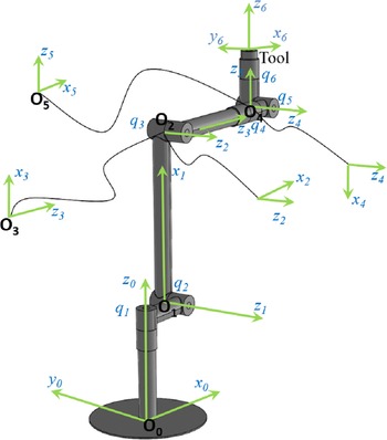
Let us consider another example extracted from ref. [Reference Klimchik, Furet, Caro and Pashkevich36], which is a typical serial manipulator with six rotational actuated joints that presents elastic deformations on both joints and links. The adopted kinematic representation is depicted in Fig. 3. Each manipulator link has a regular hollow circular cross-section and all actuated joints have the same compliance coefficients that are equal to 10–6 rad/N
 $\cdot$
m. The remaining parameters of this robot can be found in ref. [Reference Klimchik, Furet, Caro and Pashkevich36].
Kinematic representation of a typical 6 d.o.f. robot used in the illustrative example.

As in ref. [Reference Klimchik, Furet, Caro and Pashkevich36], position and orientation of the end-effector are assumed to be gathered with an accuracy of 25
 $\mu$
m and 250
 $\mu$
rad, respectively. In order to identify the elastostatic parameters of this robot, 18 measurement poses were randomly generated, each of which used for six calibration experiments with different external exciting forces/torques directed along the Cartesian axes with magnitudes set to 1000 N and 1000 N·m, driving to 108 virtual experimental test-runs.
In the frame of the GCO-based approach, it is enough to reduce the VJM model by some physical considerations only (‘Setup the VJM model’ in Fig. 2). It is worth pointing out that, from the intrinsic symmetry property associated with the Gramian constraint, the model’s parameters are inherently reduced to 153 (21 parameters for each of the 7 links and 6 joint compliances). Thus, considering just the physical aggregation of the joint compliances, the first model to be identified (MGCO147) presents 147 parameters. A second model presented in this analysis (MGCO69) departs from the assumption that, besides the joint compliances, just links 0 (base), 2 and 3 are subject to relevant compliance deviations (they are the longest links), reducing the number of parameters down to 69. This kind of assumption could be considered as reasonable as sparsing, which departs from some template assumption for the links’ compliance matrices, a similarly difficult condition to be verified in real. Nevertheless, for the sake of the completeness of this analysis, a third model (MGCO56) with 56 parameters is identified considering the full classical physical steps of aggregation and sparsing. For the weighted least-squares-based identification approach, two reduced models are considered: model MLS56, which was previously reduced according to the physical approach (symmetrization, aggregation, and sparsing) to 56 parameters, and model MLS32, which is further reduced according to the algebraic approach to the non-redundant model of the manipulator with 32 parameters [Reference Klimchik, Caro and Pashkevich35].
Table I summarizes all the identified models with their related characteristics. It is convenient to mention that, among all the models presented in Table I, only the GCO-based models led to physically meaningful models with conservative compliance matrices. The least-squares-based models did not achieve that, since this technique is expected to be sensible to the noise that overlays data in this virtual experiment.
Identification of elastostatic models for a 6 d.o.f. manipulator.

The evaluation of the validity of the GCO approach is carried out by the comparison of the identified models’ accuracy on the prediction of the compliance deviations experimented by the manipulator for 120 runs with different randomly generated poses under different loading conditions that were not used for identification. In this dataset, relevant end-effector deflections range from 9 to 41 mm. The position distance-based error (the Euclidean distance in mm) achieved by each model in each test-run is used as a metric to evaluate the models’ accuracy. To facilitate comparisons, these errors are also evaluated on a percentage basis of the end-effector deflection computed in each of these virtual test-runs.
Table II presents the results over the whole dataset, with the 95%-percentile (i.e. in 95% of all the 120 test-runs, the distance-based error of that model is lower than or equal to this value) and the RMS, on an absolute basis (mm), and with 95%-percentile and the maximum, on a percentage relative basis.
Numerical comparison of the GCO-based and least-squares-based models.

Table II shows that, besides of leading to physically meaningful models, the GCO-based approach achieved a quite acceptable accuracy. The best model was the MGCO56, with a maximum relative error of 0.62%, on a percentage basis, and a 95%-percentile of 0.072 mm, on an absolute basis. It is nearly the same as MLS32 (the best least-squares-based model), which is slightly worse with a 95%-percentile of 0.078 mm, on an absolute basis, and a maximum relative error of 0.80%. The GCO-based model MGCO69 presented a 95%-percentile of 0.084 mm, on an absolute basis, while the MGCO147 presented a maximum relative error of 0.87%, on a percentage basis. The model MLS56 performed worse than MLS32 (and the other GCO models), with a maximum relative error of 0.94%, on a percentage basis, and a 95%-percentile of 0.085 mm, on an absolute basis. It is interesting to note that, while the least-squares elastostatic identification is known to be prone to the measurement noise, the results of this section suggest that the noise did not significantly impair the accuracy of the GCO approach.
6. Experimental analyses: Elastostatic identification of a real industrial robot
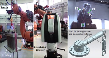
This section presents an experimental evaluation of the potential of the GCO-based approach. An elastostatic calibration of a heavy-payload industrial robot KUKA® KR-500 L480 (Fig. 1) is carried out. To accomplish that, the classical gravity-force-based experimental setup shown in Fig. 4 is used to generate the desired elastostatic deflections. The data collection and the partial pose measurement procedures, previously detailed in refs. [Reference Klimchik, Wu, Caro, Furet and Pashkevich24, Reference Wu, Klimchik, Caro, Furet and Pashkevich33], are used with this setup. According to Fig. 4, a laser tracker system that is specified with an accuracy of 50 μm within the presented setup is used to measure, before and after loading the robot in a given pose, the Cartesian coordinates of three markers (P1, P2, and P3) installed on the robot end-effector (the special tool for force application shown in Fig. 4). Each measurement taken in this way makes up a test-run, subject at least to the measuring uncertainty of
 $\sqrt{2}.50\,{\approx}\,$
70 µm.
Experimental setup for the gravity-force-based elastostatic calibration.

The maximum weight of 460.3 kg is applied on the robot end-effector, while its rated payload is 480 kg. A set of 11 robot configurations is selected for elastostatic calibration according to a target workspace of an aerospace assembly process where this manipulator is used. Using this setup, 21 measurement test-runs were randomly taken, wherein the relevant robot deflections ranged from 3.41 to 6.58 mm. The use of this data with the partial pose measurement method, which does not estimate robot orientation and makes direct optimization over the position information from the three markers, allows us making the most of the measurement data [Reference Klimchik, Wu, Caro, Furet and Pashkevich24], so that a set of 63 measuring data-points (three markers times 21 test-runs) is made available. This dataset is portioned in this study so that 45 data-points corresponding to 8 different robot poses are used to make up the 135 identification equations (three translational equations X, Y, and Z are considered for each data-point). The remaining 18 data-points, which correspond to 2 test-runs of three different robot poses, are used for model consistency check (checking dataset). Having stated that, the next step is to define the desired model structures to be identified.
Let us assume the robot KUKA KR-500 L480 contains seven compliant links connected by six compliant actuated joints. In this case, for the least-squares identification, the same reduced models used in the previous section are considered (MLS56 and MLS32). For the GCO approach, the model MGCO56 is still used due to its good performance in the previous section. In addition, from physical reasoning, departing from the model structure of MGCO69, it is observed that: (i) link 0 (in the robot base) is supposed to be much more stiffier than links 2 and 3 in a way that its compliance could be firstly disregarded; (ii) since the gravity force is supposed to be parallel to the rotation axis of joint 1, its compliance is not admitted to be identified in this experiment, so that it is also excluded from the model. This allows us to consider a second model MGCO68 (same as MGCO69, but with no compliance for joint 1) and a third model MGCO47 with 47 parameters (21 for link 2, 21 for link 3 and 5 joint compliances, with no compliance for joint 1). It is worth to mention that, although conscious of the robot’s gravity compensator influence on the equivalent compliance of joint 2 [Reference Klimchik, Caro, Wu, Chablat, Furet, Pashkevich, Thomas and Pérez Gracia25], hereinafter the more sophisticated model that includes its effects is disregarded. In fact, comparing different model structures with and without the gravity-compensator, Klimchik et al. [Reference Klimchik, Furet, Caro and Pashkevich36] showed the RMS distance-based errors do not differ more than 4.8% in the worst case. Thus, such assumption is not considered to limit this verification of the potential of the GCO approach, which could be enhanced later with a broader dataset and model structure specially adapted for that.
All the five models have been identified, presenting the following RMS position distance-based error over the identification dataset: MLS32 (0.107 mm); MLS56 (0.085 mm); MGCO47 (0.152 mm); MGCO56 (0.240 mm); and MGCO68 (0.119). The results obtained over the checking dataset are summarized in Table III.
Experimental errors using GCO-based and least-squares-based reduced models.

Table III evinces that, on both absolute and percentage basis, MGCO68 was the most accurate model with an RMS error of 0.136 mm, under a maximum relative error of 3.98%. It is almost the same as MLS56, which presented an RMS error of 0.144 mm and a maximum relative error of 4.19% and is also considered to have performed nearly the same as MLS32. Although still considered a good performance, MGCO56 presented the highest errors among the GCO models, with a maximum absolute error of 0.354 mm and a maximum relative error of 6.28%, suggesting that, at least for the cases analyzed in this work, using the classical physical reduction steps with matrices template assumptions has not provided essentially better results than physical reasoning. Overall, considering the maximum percentage-basis errors, it can be said the GCO is quite effective as the models obtained by means of this method predicted more than 93.7% of the compliance deviations of the real industrial robot in the worst case (MGCO56).
Let us perform an additional comparison between MLS32, considered as the non-redundant reference model, and MGCO68. The aggregated histogram distributions of their XYZ coordinate-based error components are depicted in Fig. 5.
Distribution of the XYZ coordinate error residuals for (left) MGCO68 and (right) MLS32.

Figure 5 shows that both models’ residuals resemble to be unbiased and normally distributed, with nearly the same standard deviation. In fact, the Lilliefors test [Reference Lilliefors51] performed over both sets of model’s residuals failed to reject this normality hypothesis at the 5% significance level. The slight means from the models’ residuals are disregarded in front of the data uncertainty (
 $\approx$
50 µm). As follows from these results, it has been made possible to identify GCO-based models that are as accurate as the best least-squares-based models. Furthermore, it is noteworthy that, in this analysis, the reduced models MLS32 and MLS56 still presented some link compliance matrices that are not positive-definite (they violate Assertion 1 with negative eigenvalues). Therefore, GCO is effective in achieving a parametric representation that retains conservativeness, consistency and, equally important, the accuracy of the elastostatic model.
7. Discussion
The benefits of the GCO method in relation to the elastostatic identification approaches that base on model reduction and least-squares technique have been evinced by numerical and experimental analyses. The main claimed advantages are: (i) the mitigation of model reduction steps and (ii) the assurance of the conservativeness of the elastostatic modeling. Both main advantages are linked to the incorporation of the Gramian property of the stiffness matrices into the elastostatic identification phase.
The benefit (i) is mainly related to the possibility of both using or not the templates for the stiffness matrix sparsing without the need of using heuristic or algebraic reduction techniques, which, as previously stated, may be difficult to apply. The benefit (ii) should be stated in terms of the implicit Gramian constraint while using the optimization process depicted in Fig 2. Symmetry and positive-definiteness are straightforward properties of the Gramian matrices, which are ultimately equivalent to the conservativeness aspect of the elastostatic modeling.
Nonetheless, it is also mandatory to clarify some limitations of the presented approach. The most important of them is the switch from a linear least-squares-based optimization approach to a non-linear optimization approach. The main concern when using a non-linear problem formulation as in Eq. (19) may be on the convergence to a global solution, since the linear least-squares technique has the strong advantage of having a closed solution defined upon some assumptions [Reference Rice48].
All the same, it should be mentioned newer techniques allied to more powerful machines may lead to feasible numerical solutions with good confidence on the convergence, although a definitive proof about this subject is unviable. In this work, a genetic algorithm [Reference Goldberg49] was used with the Global Search algorithm [Reference Ugray, Lasdon, Plummer, Glover, Kelly and Marti50] and, at least for the cases presented herein, the solutions were found according to the limiting criteria stablished for the convergence of the problem.
Two additional issues should be discussed: the linearity of the manipulator force-deflection relation and the positive-definiteness and semi-definiteness of the Gramian matrix. The former has been previously discussed [Reference Pashkevich, Klimchik and Chablat23] and some aspects are reviewed in Section 2.2, being enough to emphasize that this linear relation may present acceptable accuracy for loading magnitudes that fall in the range of the robot payload [Reference Klimchik, Furet, Caro and Pashkevich36]. The latter issue is more clearly understood considering that Theorem 1 claims for a semi-definite stiffness matrix while some previous theoretical works may claim for a strict positive-definite stiffness matrix [Reference Chen and Kao44]. The differences between these properties are subtly given in Definition 1 and Assertion 1. In the robotic community, both definitions have been accepted with some works using the more flexible semi-definite condition as enough [Reference Pashkevich, Klimchik and Chablat23]. This is also the understanding of this work. Nonetheless, the positive-definite aspect could still be directly addressed by taking Corollary 1 (Section 2.3) as an additional constraint for the process depicted in Fig 2.
Lastly, it is important to emphasize the elastostatic calibration is a broad process comprised of other important steps, such as experiment definition and optimization, data collection and treatment, and finally the tunning of the model parameters by means of an optimization approach over the experimental data. The method presented in this work can be readily and easily used within this framework with the advantage of preserving the physical meaning of the parametric model with good accuracy.
8. Conclusion
This paper has presented the GCO approach as a complementary solution to the elastostatic identification process of industrial manipulators, which remits to different practical and theoretical challenges. The main research focus is on the parametric identification phase, which is usually translated into an optimization process that can be noticeably impaired by the model complexity and the measurement noise from the real environment. Attention is paid to the underlying conservative nature of the elastic models, stated in terms of symmetry and positive-definiteness of the joint stiffness matrices.
In contrast to previous approaches, where algebraic, physical, and heuristic reduction techniques are allied to the least-squares optimization, the Gramian nature of the stiffness matrices has been found out to be used in a novel non-linear parametric tuning process. Noisy numerical and experimental data were used along the identification of models of different complexity. In the experimental study, a GCO-based model of a real industrial manipulator has been obtained with an accuracy of 0.197 mm while predicting the compliance deviations under a loading of 4.6 kN.
An important finding is that, while previous approaches may fail in achieving a conservative parametric representation of the stiffness matrices, the GCO-based identification always yields to a conservative model. Furthermore, as evinced by the results presented throughout this paper, equally important is the capability of the technique in delivering accurate elastostatic modeling of serial manipulators in the presence of noise, which highlights the practical benefit of the presented approach. Future developments will be concentrated on the use of this technique to identify models to be used in compliance error compensation and task-based trajectory performance evaluation.
Disclosure statements
The authors declare all the pertinent clauses in the following.
Conflicts of interest
The authors declare none.
Financial support
This research received no specific grant from any funding agency, commercial, or not-for-profit sectors.
Authors contributions
W. R. de Oliveira conceived and designed the study. L. G. Trabasso conceived and supervised the research, provided the lab test-bench, and jointly wrote the article.