I. INTRODUCTION
Superaustenitic stainless steel (SASS), AISI 904L, an alloy of Fe–Cr–Mo contains higher amounts of nickel compared to the conventional austenitic grades. SASS also exhibits excellent corrosion resistance and high-temperature strength, which puts them at the forefront of metallurgical technology. These materials have received recent attention from the U.S. Navy for their use in the new fleet of Advanced Double Hull (ADH) combatant ships. Reference Dupont, Banovic and Marder1 The presence of high molybdenum content along with the increased levels of chromium and nitrogen gives this stainless steel grade excellent resistance to pitting, crevice, and chloride stress corrosion cracking. Reference Kuhn and Medlin2 The addition of nitrogen, along with enhancing the mechanical properties of these steels, is also useful in delaying and/or even preventing the formation of harmful precipitates. These steels have improved mechanical properties such as weldability and formability compared to the conventional stainless steels and Ni-based superalloys. Researchers have reported that SASS exhibits superior impact toughness and can maintain their impact properties even at low subzero temperatures, adjudging them as best candidate material for cryogenic applications. Reference Nagarajan and Rajendran3–Reference Woo and Kikuchi5
Koutsoukis et al. Reference Koutsoukis, Redjaımia and Fourlaris6 investigated the aging characteristics of two different superaustenitic steel grades. The samples of these steel grades were exposed to isothermal heat treatment in the temperature range of 650–950 °C for aging between 0.5 and 3000 h, followed by quenching in water to room temperature. The authors reported the formation of secondary phases, including sigma phase (σ), chi phase (χ), Laves phase, and β-Cr2N phase during the heat treatment. Also, they claimed that there was a loss of ductility and toughness in addition to an increase in yield and tensile strength of these steel grades. Sathiya et al. Reference Sathiya, Aravindan, Ajith, Arivazhagan and Noorul Haq7 carried out bead on plate welding on AISI 904L using gas metal arc welding process and used gray relational analysis to optimize the weld process parameters.
Balamurugan et al. Reference Balamurugan, Kumar Mishra, Sathiya and Naveen Sait8 carried out studies on optimizing the friction welding process parameters for joining AISI 904L steel using genetic algorithm. The authors claimed that a better fatigue life was obtained for friction welded AISI 904L on using the optimized parameters.
Sathiya and AbdulJaleel Reference Sathiya and AbdulJaleel9 investigated the effect of shielding gases on the microstructure and mechanical properties of hybrid laser welded SASS. The authors reported that the shielding gas mixture of 50% He + 45% Ar + 5% O2 improved the tensile strength. It was reported by Hertzman et al. Reference Hertzman, Jargelius Pettersson, Blom, Kivineva and Eriksson4 that autogenous gas tungsten arc welding (GTAW) of superaustenitic steel with shielding gases and arc lengths yielding nitrogen content in excess of 0.2% resulted in porosity. Banovic et al. Reference Banovic, DuPont and Marder10 investigated the dilution levels during GTA welding of superaustenitic steels using Inconel 625 and Inconel 622 fillers. The authors further reported that the dilution levels decreased with increasing filler-metal feed rate and decreasing arc power.
Lippold and Koteki Reference Lippold and Koteki11 recommended the use of high Mo rich Ni-based filler metals to improve the pitting corrosion resistance of AISI 904L. The authors claimed that a filler wire with atleast 9% Mo was essential to match the pitting resistance of the 6% Mo base metals. Zambon et al. Reference Zambon, Ferro and Bonollo12 investigated the CO2 laser welding of 3-mm-thick plates of SASS. The authors observed an imperceptible heat affected zone (HAZ) which allowed the retention of high toughness.
Kumar et al. Reference Kumar and Shahi13 investigated the effect of heat input on the mechanical properties of stainless steel joints obtained from GTAW. The authors inferred the grain coarsening at the HAZ in all the cases, and claimed that the extent of grain coarsening increases with increasing heat input.
Manikanta Sriram et al. Reference Manikanta Sriram, Hayagreev, Ajay Shri Bhuvanesh, Ajari Babaseaheb Abhishek, Devendranath Ramkumar, Arivazhagan and Narayanan14 investigated the PCGTA welding of AISI 304L using ERNiCu-7 and ERNiCrMo-3 fillers. The authors reported that the tensile strength of ERNiCrMo-3 weldments was found to be higher. Also important, they addressed that the PCGTA welding resulted in grain refinement. As claimed by other researchers, Reference Farahani, Shamanian and Ashrafizadeh15–Reference Devendranath Ramkumar, Mithilesh, Varun, Reddy, Arivazhagan, Narayanan and Gokul Kumar17 the PCGTAW resulted in controlled heat input which contributes for lower residual stresses, distortion, etc.
As evident from the open literature, there exists a huge demand for AISI 904L in versatile engineering applications. Hitherto, limited studies had been reported on the weldability of SASS, AISI 904L using conventional arc welding process. Since both the CCGTA and PCGTA welding processes are economical and efficient in most situations, this work assumes significance. This study addresses the weldability of AISI 904L by the CCGTA and PCGTA welding processes using ER2553 and ERNiCrMo-4 fillers. The structure–property relationships of these weldments are ascertained using the combined techniques of optical microscopy (OM) and scanning electron microscopy (SEM).
II. EXPERIMENTAL PROCEDURE
A. Base metals and welding procedure
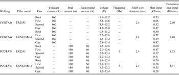
The chemical composition analysis was carried out on the as-received base metal AISI 904L and the filler wires using dry spectroscopic methods. The nominal chemical composition of the base and filler metals is represented in Table I. The as-received base metal was sliced to coupons of dimensions of 150 mm × 55 mm × 5 mm using wire-cut electrical discharge machining (WEDM) for carrying out the welding process. Standard V-Butt configurations (single V-groove having a root gap of 2 mm, size land of 1 mm, and an included angle of 60°) were used on these base metals before welding. A specially designed welding fixture with grooved copper back plate was used to facilitate heat dissipation during welding. The fixture was clamped firmly to keep the base metals in proper alignment, so as to provide firm gripping and avoid bending during the welding process. The welding trials had been carried out using Kemppi MasterTIG welding equipment. The CCGTA and PCGTA weld process parameters were established based on the iterative trials and the parameters chosen for the current study are shown in Table II. Both the CCGTA and PCGTA welding techniques were carried out using ER2553 and ERNiCrMo-4 filler wires. Ensued to welding, the weldments were subjected to gamma ray nondestructive testing (NDT) analysis to determine the existence of surface or subsurface defects. Further, these weldments were sliced to specimens of different dimensions according to standards using WEDM to carry out various metallurgical and mechanical characterization tests which are broadly outlined in the subsequent sections.
Chemical composition of the base and filler metals.

Process parameters used.

B. Metallurgical and mechanical characterization of weldments
The macro/microstructure examinations were carried out on the cross-sectional samples (covering the multiple zones including base metal, HAZ, and the fusion zone) with dimensions 30 mm × 10 mm × 5 mm obtained from the weldments, keeping weld as center. Standard metallographic procedures, including polishing with emery sheets of SiC of grit sizes varying from 220 to 1000, followed by disc polishing using diamond paste and aerosol were used on these samples to obtain a mirror finish of 1µ on the weldments. Electrolytic etching (10% oxalic acid; 6 V DC supply; current density 1.6 A/cm2) was used to reveal the grain structure of the different zones of these weldments. Microstructure examination was carried out using OM and SEM techniques. SEM/energy dispersive x-ray analyser (EDAX) point analysis and line mapping analysis were also performed to understand the movement of elements across the weldments.
Microhardness studies were carried out on the transverse coupons of the weldments. Hardness measurements were taken across the entire width of the weldments (keeping weld as center) using Vicker's microhardness tester. A standard test load of 500 gf for a dwell period of 10 s was used and measurements were carried out at regular intervals of 0.25 mm. Transverse tensile studies were carried out on the coupons prepared as per ASTM: E8/8M standard, using the Instron universal testing machine. The cross-head velocity was set to 2 mm/min to produce a strain rate of 3.3 × 10⁻⁴ s−1. This strain rate is well in range as that prescribed by ASM International Handbook of Mechanical Testing and Evaluation. 18 Charpy V-notch impact studies were also carried out on the subsized samples (55 × 10 × 5 mm3) obtained as per ASTM: E23-12C standard to assess the response of the weldments toward sudden load. Notches were made in such a way that the fracture occurred only within the weld fusion zones. Three trials of experiments were performed for assessing the tensile properties of the weldments. Similarly, two trials in each case of root and cap passes were tested for impact toughness to ensure repeatability of results. The samples were cleaned ultrasonically before the images were captured. SEM analysis was carried out on the fractured samples to comprehend the mode of fracture. To assess the ductility and soundness of these weldments, root bend test was carried out on coupons with dimensions 152 mm × 38 mm × 4 mm, as per the ASTM: E190-92 standard.
III. RESULTS
A. Base metal
The chemical composition analysis of the AISI 904L showed the enriched amounts of Ni and Cr along with the presence of Mo, Cu, and N (Table I). The average ultimate tensile strength and 0.2% proof strength of unwelded base metal were 613 and 270 MPa, respectively, and the average impact toughness was found to be 66 J.
B. Macrostructure examination
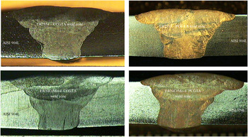
It was clearly inferred from the cross-sectional macrographs shown in Figs. 1(a)–1(d) that a proper fusion was accomplished while using ER2553 and ERNiCrMo-4 fillers. Further, the gamma ray NDT analysis confirmed that the weldments were free from surface and subsurface defects.
Macrophotographs of CCGTA and PCGTA weldments of AISI 904L.

C. Microstructure studies
Both the interfacial and weld microstructures of the weldments had been characterized using optical and SEM techniques. Line and point mapping analysis were also carried out at various zones of the weldments and are outlined in the following sections.
1. CCGTA weldments using ER2553 and ERNiCrMo-4 filler
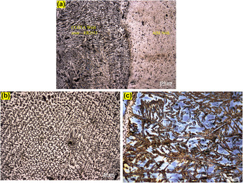
Interface microstructure of ER2553 weldment showed the absence of unmixed zone or formation of secondary phases [Fig. 2(a)]. The grain growth was different at various zones of the weld zone. Skeletal delta ferrite morphology was observed in the middle and root pass of the weld zone [Fig. 2(b)]. The different modes of austenite such as grain boundary austenite, Widmanstatten austenite, and inter/intragranular austenite along with ferrite were observed at the cap of ER2553 weld zone [Fig. 2(c)].
(a) Interface microstructure, (b) fusion zone microstructure at the root, and (c) fusion zone microstructure at the cap region of CCGTA weldments using filler.

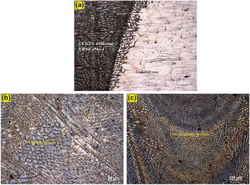
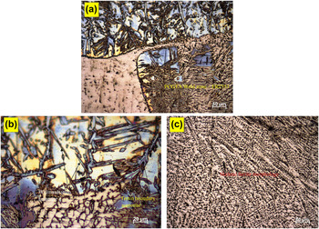
In the case of ERNiCrMo-4 weldment, the interface microstructure revealed the presence of unmixed zone at the HAZ [Fig. 3(a)]. Parent metal of AISI 904L showed the typical grain and grain boundaries. Cellular and dendritic growth was observed at the cap region of the fusion zone, whereas fine equiaxed grain growth dominated the middle and root passes of ERNiCrMo-4 fusion zone [Figs. 3(b) and 3(c)].
(a) Interface microstructure, (b) fusion zone microstructure at the cap, and (c) fusion zone microstructure at the root pass region of CCGTA weldments using ERNiCrMo-4 filler.

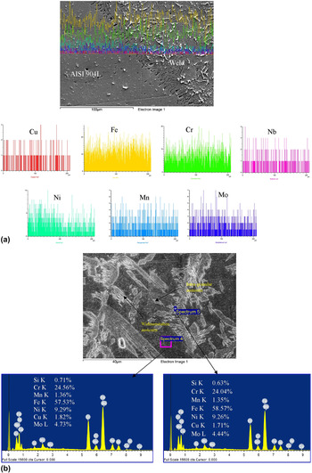
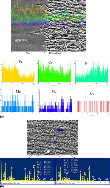
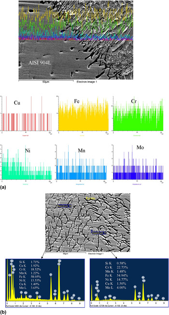
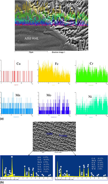
Line mapping analysis conveyed that the elemental movement was meager across the ER2553 weldment [Fig. 4(a)]. SEM/EDAX point analysis of ER2553 fusion zone clearly depicted the presence of almost the same amounts of Fe, Cr, Ni, and Mo at both the weld matrix and the phases [Fig. 4(b)]. Similarly, the line mapping analysis of ERNiCrMo-4 weldment clearly portrayed the movement of Fe from the parent metal to the fusion zone. Also the elements Ni and Mo migrated from fusion zone to the parent metal [Fig. 5(a)]. SEM analysis showed the presence of cellular grains at the fusion zone and the EDAX point analysis divulged the presence of almost equal amounts of Ni, Cr, Fe, Mo, and W at different locations. Tiny, white phases, enriched with Mo and Cr were also observed at the fusion zone [Fig. 5(b)].
(a) Line mapping analysis on the CCGTA weldment of AISI 904L using ER2553 filler. (b) SEM/EDAX point analysis on the CCGTA weldment of AISI 904L using ER2553 filler.

(a) Line mapping analysis on the CCGTA weldment of AISI 904L using ERNiCrMo-4 filler. (b) SEM/EDAX point analysis on the CCGTA weldment of AISI 904L using ERNiCrMo-4 filler.

2. PCGTA weldments using ER2553 and ERNiCrMo-4 fillers
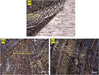
The absence of unmixed zone was also observed from the interfacial microstructures of both the weldments [Figs. 6(a) and 7(a)]. As discussed in Sec. III. C. 1, the cap region of PCGTA weldment using ER2553 showed the presence of different austenitic morphologies such as grain boundary austenite, Widmanstatten, and intragranular austenite [Fig. 6(b)] whereas the middle and root regions exhibited vermicular/skeletal delta ferrite [Fig. 6(c)]. Multidirectional grain growth containing cellular and dendritic grains at the cap region, and fine equiaxed grains at the root of ERNiCrMo-4 were observed [Figs. 7(b) and 7(c)].
(a) Interface microstructure, (b) fusion zone microstructure at the cap and (c) fusion zone microstructure at the root region of PCGTA weldments using ER2553 filler.

(a) Interface microstructure, (b) fusion zone microstructure at the cap, and (c) fusion zone microstructure at the root region of PCGTA weldments using ERNiCrMo-4 filler.

It was inferred from the line mapping analysis of ER2553 weldment shown in Fig. 8(a) that the elemental movement from the parent metal to fusion zone or vice-versa was meager. SEM morphology at the root of the ER2553 weld zone clearly showed the presence of δ-ferrite and the matrix being richer in Ni, Cr, Fe, and Mo. The white secondary phases were also enriched with these elements [Fig. 8(b)]. Similarly, the line mapping analysis of ERNiCrMo-4 weldment [Fig. 9(a)] showed a similar trend of elemental migration as observed in the CCGTA weldment using the same filler. Cellular growth was clearly witnessed in the SEM morphology, and the EDAX point analysis showed the presence of Ni, Cr, Fe, and Mo. The tiny, white secondary phases enriched with Mo were distributed throughout the fusion zone [Fig. 9(b)].
(a) Line mapping analysis on the PCGTA weldment of AISI 904L using ER2553 filler. (b) SEM/EDAX point analysis on the PCGTA weld zone of AISI 904L using ER2553 filler.

(a) Line mapping analysis on the PCGTA weldment of AISI 904L using ERNiCrMo-4 filler. (b) SEM/EDAX point analysis on the PCGTA weld zone of AISI 904L using ERNiCrMo-4 filler.

D. Mechanical characterization
The weldments were characterized for their mechanical properties by subjecting them to different mechanical tests and their outcomes are reported in the subsequent sections.
1. Hardness measurements
a. CCGTA weldments
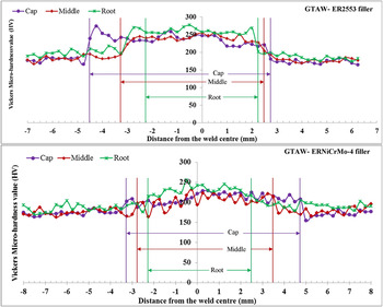
Hardness studies showed that the weld zones of both the fillers exhibited greater hardness compared to the parent metal (Fig. 10). The average weld hardness of ER2553 weldment was found to be 243 HV and the average hardness of the weldment was 203 HV. Among the different passes, the root region of ER2553 fusion zone showed greater hardness (257 HV) compared to the cap and middle pass. The average hardness of the weld zone using ERNiCrMo-4 filler was found to be 215 HV which was slightly higher than that of the parent metal (192 HV). Similarly, in this case, the root pass exhibited higher hardness of 230 HV. The cumulative hardness data of CCGTA weldments are shown in Table III.
Hardness plot at the different passes of the CCGTA weldments.

Hardness data of CCGTA weldments of AISI 904L.

b. PCGTA weldments
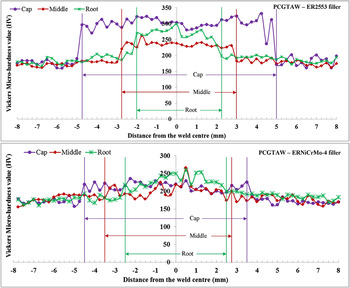
As discussed in Sec. III. D. 1. a, the hardness of PCGTA fusion zones was comparatively higher than that of the parent metal. The hardness trend of PCGTA weldment shown in Fig. 11 vividly conveyed that the weld zone using ER2553 exhibited greater hardness of 265 HV compared to the parent metal. In this case, the cap zone showed maximum hardness of 298 HV compared to the other passes of the weldment; whereas an average hardness value of 214 HV was observed at the fusion zone using ERNiCrMo-4 filler. The cumulative hardness data of the PCGTA weldments are provided in Table IV. Figure 12 shows the comparison chart of CCGTA and PCGTA weldments using ER2553 and ERNiCrMo-4 fillers.
Hardness plot at the different passes of the PCGTA weldments.

Hardness data of PCGTA weldments of AISI 904L.

Comparison of hardness at different passes of the weldments.

2. Tensile studies
a. CCGTA weldments
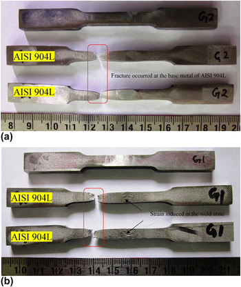
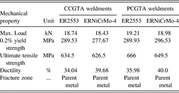
Tensile studies showed that the fracture occurred at the parent metal AISI 904L for both the filler metals (Fig. 13). The average tensile properties of CCGTA and PCGTA weldments are shown in Table V.
Photographs of the fractured tensile samples obtained from CCGTAW using (a) ER2553 and (b) ERNiCrMo-4 filler.

Average tensile properties of AISI 904L weldments.

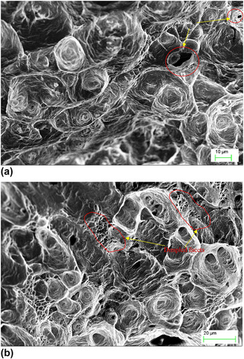
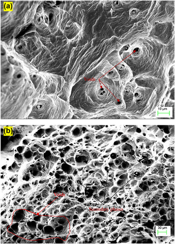
The average tensile strength and 0.2% yield strength of ER2553 weldments were reported to be 634.5 and 289.5 MPa, respectively. Similarly, the weldments using ERNiCrMo-4 filler exhibited an average tensile strength of 626.5 MPa and proof strength of 277.67 MPa. Although the fusion zone of ERNiCrMo-4 had undergone severe plastic strain, the fracture was witnessed at the parent metal in all the trials [Fig. 13(b)]. SEM fractograph of ER2553 weldment [Fig. 14(a)] showed the presence of scarce amounts of macrovoids with shiny tearing ridges spread throughout the fractured surface. Dimpled facets along with microvoids in the fibrous ridges were observed as the fractographic features of ERNiCrMo-4 weldments [Fig. 14(b)].
SEM fractographs of the tensile tested CCGTA weldments of AISI 904L using (a) ER2553 and (b) ERNiCrMo-4.

b. PCGTA weldments
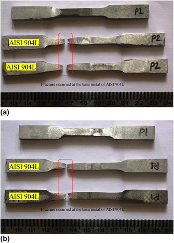
Similar to CCGTA weldments, the PCGTA weldments also experienced tensile fracture at the parent metal of AISI 904L (Fig. 15). The average tensile strength of ER2553 weldments (666 MPa) was comparatively greater than ERNiCrMo-4 weldments (649.5 MPa). The average ductility of ERNiCrMo-4 weldments (40%) was higher than that of the ER2553 weldments (35.98%). SEM topology showed the presence of scarce voids and clamshell ridges on the fractured surface of ER2553 weldment [Fig. 16(a)]. Approximately uniform sized microvoids and dimpled facets with shiny tearing ridges were the characteristic features observed on ERNiCrMo-4 weldments [Fig. 16(b)]. Also, the presence of secondary phases on these voids was witnessed.
Photographs of the fractured tensile samples obtained from PCGTAW using (a) ER2553 and (b) ERNiCrMo-4 filler.

SEM fractographs of the tensile tested PCGTA weldments of AISI 904L using (a) ER2553 and (b) ERNiCrMo-4.

E. Impact test
1. CCGTA weldments
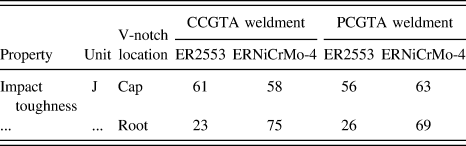
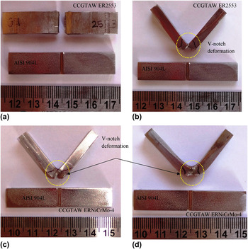
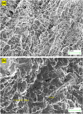
The weldments were characterized for their impact toughness by conducting Charpy V-notch studies. Cumulative impact test data are represented in Table VI. Both the cap and root passes of the weld zone were subjected to impact loading and V-notches were made in the corresponding locations. In the case of ER2553 weldment, the results showed that the cap zone demonstrated better impact toughness (61 J) compared to the root weld (23 J) [Figs. 17(a) and 17(b)]. Contrarily, the root weld (75 J) of ERNiCrMo-4 weldment demonstrated better toughness as compared to the cap zone (58 J) [Figs. 17(c) and 17(d)]. The results showed that the impact toughness of the root pass ERNiCrMo-4 weldment exhibited toughness values which were comparatively greater than the unwelded parent metal (66 J). SEM fractographs revealed the shiny, foamy appearance on the fractured surface of ER2553 weldment; whereas the cleavage facets dominated in the SEM morphology of ERNiCrMo-4 weldment [Figs. 18(a) and 18(b)].
Impact test results of AISI 904L weldments.

Impact tested CCGTA weldments using ER2553 filler showing (a) cap and (b) root locations, and ERNiCrMo-4 filler showing (c) cap and (d) root locations, respectively.

SEM fractographs of impact tested CCGTA weldments using (a) ER2553 and (b) ERNiCrMo-4 filler, respectively.

2. PCGTA weldments
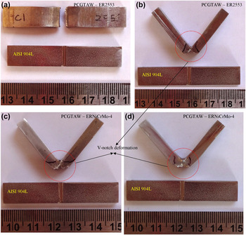
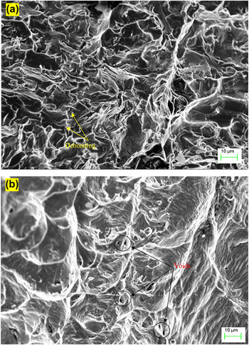
As stated in Sec. III. E. 1, the cap weld of ER2553 weldment exhibited lower toughness of 26 J. As evident from the impact test photographs, the cap weld using ER2553 ruptured into two halves; notch deformation had occurred in all the remaining cases [Fig. 19(a) and 19(b)]. The average impact toughness of cap and root weld of ERNiCrMo-4 weldment was observed to be 63 and 69 J, respectively. The fractured samples of ERNiCrMo-4 weldments are shown in Figs. 19(c) and 19(d). SEM fractographs divulged the presence of cleavage facets with the debonded layers on the fractured surface of ER2553 weldment [Fig. 20(a)]; whereas the topology of ERNiCrMo-4 weldment showed scarce amounts of microvoids in the shiny tearing ridges [Fig. 20(b)].
Impact tested PCGTA weldments using ER2553 filler showing (a) cap and (b) root locations, and ERNiCrMo-4 filler showing (c) cap and (d) root locations, respectively.

SEM fractographs of impact tested PCGTA weldments using (a) ER2553 and (b) ERNiCrMo-4 filler, respectively.

F. Bend test
Root bend test was carried out to ensure the ductility and soundness of the welded joints. It was inferred that CCGTA weldments using ER2553 showed a complete 180° bend. However, fissures and cracks were found running across the weld lip or interface [Fig. 21(a)]. PCGTA weldments of ER2553 showed better results compared to CCGTA weldments and a very small void was observed at the middle of the weld interface [Fig. 21(c)]. Both the CCGTA and PCGTA weldments using ERNiCrMo-4 demonstrated better ductility and soundness when subjected to bending test [Figs. 21(b) and 21(d)]. No cracks or fissures were observed on the surface/surface of these welds. The bend test results of the CCGTA and PCGTA weldments are represented in Table VII.
Photographs of the bend tested samples of AISI 904L welds.

Bend test results.

IV. DISCUSSION
It was well observed that successful joints of AISI 904L could be established by CCGTA and PCGTA welding processes using ER2553 and ERNiCrMo-4 fillers. Macrostructure studies divulged that perfect fusion occurred with the base metals on using the established process parameters and the filler metals (Fig. 1). Further, NDT technique confirmed that there were not any observable cracks on any of these weldments.
There was no prominent formation of unmixed zone on the CCGTA weldments obtained using ER2553 filler wire, whereas the ERNiCrMo-4 weldments did observe an unmixed zone. The formation of this unmixed zone could be reasoned to the differences existing in the chemical composition and thermal gradients. As reported by Kou and Yang, Reference Kou and Yang19 a dissimilar filler metal can change the composition of the bulk weld metal and make the liquidus temperature of the weld metal significantly different from that of the base metal. On the contrary, the interface microstructure of PCGTA weldments showed the absence of unmixed zone while using either of these filler metals, which should be due to the controlled heat input developed during the welding process.
Fusion zone microstructure at the cap of both CCGTA and PCGTA weldments of ER2553 filler was observed to have different forms of austenite such as grain boundary austenite, elongated platelets of allotriomorphic, wedge shaped Widmanstätten austenite, and intergranular precipitates originating from ferrite [Figs. 2(c) and 6(b)]. Similarly, skeletal delta ferrite was observed at the root pass of both the ER2553 weldments which clearly elucidated the ferritic–austenitic mode of solidification. As reported by Lippold et al., Reference DuPont, Lippold and Kiser20 moderate cooling rates and/or low Cr/Ni ratio would result in vermicular or skeletal ferrite morphology at the fusion zone of the stainless steel. Mirshekari et al. Reference Mirshekari, Tavakoli, Atapour and Sadeghian21 reasoned out for the formation of skeletal delta-ferrite morphology in the fusion zone of 304L to the fusion zone being enriched in ferrite-promoting elements such as Cr and Mo and being depleted in austenite-promoting elements such as Ni. However, the presence of skeletal delta ferrite in the fusion zone improved the hot cracking resistance of these weldments.
As reported by Gideon et al., Reference Gideon, Ward and Biddle22 the formation of grain boundary austenite and Widmanstätten side-plates occurred early at higher temperatures, while the intragranular austenite particles require a greater driving force and precipitate later at a lower temperature. Further, the authors reported that the formation of a finer and coarse structure within the weld metal was totally dependent on the level of undercooling. This would be expected in a welding process, since the weld metal in the cap region would cool down more quickly as a result of the lower ambient temperature during the start of welding.
Ferrite measurements were carried out at the fusion zone of the ER2553 weldments. The results showed that CCGTAW fusion zone of ER2553 exhibited the higher amounts of ferrite (39%, 29%, and 18%), whereas the ferrite percentage was found lower for PCGTAW fusion zone (16%, 7%, and 3%) in the cap, middle, and root passes of the weldment. The variations in the ferrite count at different passes can be attributed to the reduction of dilution while advancing from root to cap pass. Similar observations were reported by Rahmani et al. Reference Rahmani, Eghlimi and Shamanian23 This may be reasoned to the dissolution of ferrite upon reheating of the zones during multipass welding. Various researchers addressed these dissolution issues in stainless steel welding. Reference Lundin and Chou24,Reference Chen and Chou25 The formation of higher amounts of ferrite in the cap of the weld zone could be attributed to the faster cooling rate compared to the root. However, the weldments using ER2553 exhibited moderate amount of ferrite and higher amount of austenite as prescribed by Norsok standard for welding and piping inspection. 26 This standard recommended a minimum content of 30% austenite in the final bead and root pass to accept the welded joints.
Multidirection grain growth containing cellular and columnar dendrites was observed for both the ERNiCrMo-4 weldments [Figs. 3(b) and 7(b)]. The middle and root passes of ERNiCrMo-4 weldments were observed to have fine, well-organized equiaxed grain growth. As reported by Kuo, Reference Sindo27 heterogeneous nucleation aided by constitutional supercooling would promote the formation of equiaxed grains in the weld metal. Further, the formation of fine equiaxed grains in the fusion zone has two main advantages. First, the fine grains help in reducing the susceptibility to solidification cracking during welding and second, they would improve the mechanical properties of the weld, such as the ductility and fracture toughness. Reference Sindo27 Also, the welds produced by ERNiCrMo-4 filler resulted in a complete austenitic matrix.
The elemental movement across the ER2553 weldments was found to be scanty. This could be attributed to the matching composition of the base and filler metals. The migration of elements (for the weldments using ERNiCrMo-4) was observed from the fusion zone to HAZ and vice-versa due to the mismatching composition. In addition to this, the point analysis showed that the very fine Mo rich phases observed as segregates, appeared in the fusion zone.
The hardness profile indicated that the fusion zone of PCGTA weldment using ER553 filler experienced greater hardness compared to the CCGTA weldment. This could be credited to the controlled heat input causing the faster cooling rate during the PCGTA welding process, which contributed for grain refinement. The hardness was observed to be greater in the cap region of the ER2553 weldment. This can be ascertained by the presence of ferrite and austenite of different morphologies. Moreover, the ferrite measurements also confirmed that the amount of ferrite was greater in the cap region as compared to other passes which in turn contributed for greater hardness. In addition, the cap region also experienced higher cooling rate compared to fill passes resulting in greater weld hardness.
CCGTA and PCGTA weldments using ERNiCrMo-4 filler elucidated that the average hardness trend at the fusion zone was slightly higher than that of the parent metal. The average hardness at the fusion zone of both the CCGTA and PCGTA weldments was almost similar (Fig. 12). The present study inferred that the welding current has not had much influence on the hardness at the fusion zone for this particular case of filler metal. In both the cases, the root pass of the fusion zone attained the maximum hardness. This can be substantiated from the formation of fine equiaxed, cellular dendritic growth at the root pass as evident from the microstructure observations. Similar observations were reported elsewhere. Reference Farahani, Shamanian and Ashrafizadeh15 It was inferred from Table II that the PCGTA welding exhibited lower heat inputs compared to CCGTAW which in turn accelerated the cooling rate. As reported by Barnhouse and Lippold, Reference Barnhouse and Lippold28 lower heat inputs with high cooling rates result in grain refinement, which in turn enhance hardness values at the fusion zone. These outcomes fall in agreement with the present study.
Tensile studies corroborated that the weldments experienced fracture at the parent metal of AISI 904L (Figs. 13 and 15). The studies clearly portrayed that the ultimate tensile strength of PCGTA weldments was greater than the CCGTA weldments and, that among the fillers, ER2553 exhibited higher tensile strength. As stated, the grain refinement in the PCGTA weldments contributed to greater strength. It is inferred from the tensile studies that the weld strength was greater than that of the parent metal. The presence of nominal amounts of ferrite and austenite in the fusion zone of ER2553 weldments augmented better weld strength. The austenitic phase became richer and stronger due to the interstitial solid solution strengthening effect exhibited by nitrogen in the ER2553 filler wire. Hence, the hardness and strength of the fusion zone were found similar or greater than that of the base metal. This was also supported by the microstructure studies through OM and SEM techniques. Similarly, the richer constituents of alloying elements such as Cr, W, Mo, and V in the ERNiCrMo-4 filler exhibited solid solution strengthening effect Reference DuPont, Lippold and Kiser20 and thereby imparting greater strength at the weld zone. The results also elucidated higher proof strength and ductility for PCGTA weldment using ERNiCrMo-4 filler. The presence of substantial amounts of micro and macrovoids with dimpled facets in the fibrous network inferred that the PCGTA weldments using ERNiCrMo-4 undergo ductile fracture. Moreover, the intermetallic phases were also seen on the ERNiCrMo-4 PCGTA weldments and these phases occupied the void spaces. As evident from the microstructure analysis, these secondary phases were enriched with Mo and Cr. Comparing the SEM fractographs of ER2553 weldments [Figs. 14(a) and 16(a)], the voids were found to be more for PCGTA weldments than CCGTA weldments. The presence of voids indicated that the PCGTA weldments absorbed more energy during rupture than the CCGTA weldments. Since all the weldments produced satisfactory results in the tensile tests, the weldments were subjected to further destructive testing conditions to assess the overall mechanical properties.
To study the response of the weldments toward the sudden loads, Charpy V-notch studies were carried out on the weldments and the grooves were taken at the different passes vis-à-vis cap and root, and tested. The results showed that the cap region of ER2553 weldments exhibited higher impact toughness compared to the root pass, whereas better impact results were ascertained at the root pass of ERNiCrMo-4 weldments. The increased toughness in the cap zone could be attributed to the presence of higher amounts of ferrite in the cap zone of ER2553 weldments which was also ascertained by the ferrite measurements. As reported by Devendranath Ramkumar et al., Reference Devendranath Ramkumar, Thiruvengatam, Sudharsan, Mishra, Arivazhagan and Sridhar29 the balanced proportion of ferrite and austenite enhances the toughness of the weld zone. In the case of ERNiCrMo-4 weldments, the root pass exhibited comparatively greater toughness than the parent metal. This may be imputed to the presence of finer grains at the root passes. Also, the impact results conveyed that the toughness values at the root pass of ERNiCrMo-4 weldments were greater, even compared to the toughness of the unwelded base metal. The presence of fully austenitic structure in the fusion zone of ERNiCrMo-4 could have attributed to the solid solution strengthening effect and in turn augmented the toughness. Notch plastic deformation without undergoing a complete rupture had occurred at the CCGTA and PCGTA weldments using ERNiCrMo-4 filler. Further, SEM micrographs showed the presence of scarce voids running in the foamy fibrous network confirming the mixed mode of fracture. The PCGTA weldments were observed to have minor amounts of voids and additionally, the presence of clamshell ridges validated cleavage fracture.
The guided bend test was carried out on the root of the weldments (Fig. 21). No cracks and fissures were observed for both the CCGTA and PCGTA weldments using ERNiCrMo-4 which ensured the ductility and soundness of the welds. Conversely, the CCGTA weldments using ER2553 were observed to have a crack running across the weld lip. However, the PCGTA weldments did not observe any cracks during the test trials. The reason for poor bend ductility of CCGTA weldments using ER2553 filler could be attributed to the greater hardness at the joint interface as compared to the parent metal. As explained by Fuji et al., Reference Fuji, North, Ameyama and Futamata30 the poor bend ductility can be attributed to the combination of high hardness adjacent to the joint interface, the presence of unrelieved residual strain at the joint interface, and also to the formation of intermetallic phases during the welding operation. Exhaustive study shall be required to reason out the poor bend ductility of CCGTA weldments using ER2553 and would be addressed in the future studies of the authors.
In a nutshell, for the first time, this study addressed the CCGTA and PCGTA welding of SASS using two different filler wires, ER2553 and ERNiCrMo-4. The structure–property relationships of these weldments have been studied extensively and would be the major literature source for the upcoming research works on this grade of stainless steel. The outcomes reported in the study would be highly beneficial to the marine, nuclear, and petrochemical industries using these grades of stainless steels.
V. CONCLUSIONS
The following outcomes were deduced from the investigations on the weldability and characterization studies of SASS, AISI 904L.
-
(1) Sound welds of SASS could be ascertained on using continuous and pulsed current GTAW techniques using ER2553 and ERNiCrMo-4 fillers.
-
(2) No grain coarsening or formation of secondary phases was observed at the HAZ in any of the cases; an unmixed zone appeared in the CCGTA weldment using ERNiCrMo-4 due to the mismatching composition.
-
(3) Microstructure studies corroborated the presence of different austenite morphologies in the cap zone and skeletal delta ferrite in the middle and root pass of both the ER2553 weldments. Fine, cellular, and equiaxed dendrites were observed at the filler and root pass of ERNiCrMo-4 weldments which could be attributed to the reheating of the zones and the moderate cooling rates.
-
(4) Greater hardness at the cap pass of fusion zone using ER2553 filler was due to the higher amounts of ferrite. Similarly, the refinement of grains enhanced the fusion zone hardness at the root pass of ERNiCrMo-4 weldment.
-
(5) Tensile studies corroborated that the fracture occurred at the parent metal, AISI 904L. This clearly inferred that the weld strength was greater compared to the parent metal. In general, the PCGTA weldments offered better tensile properties as compared to CCGTA weldments.
-
(6) The presence of nominal amounts of ferrite and austenite in the fusion zone of ER2553 weldments and the solid solution strengthening effect exhibited due to the various alloying elements such as Cr, Mo, Co, W, and V in the ERNiCrMo-4 demonstrated for better tensile strengths.
-
(7) Impact studies demonstrated that the root pass of the ERNiCrMo-4 weldments exhibited greater impact toughness compared to the parent metal. In the case of ER2553 weldments, the cap zone exhibited greater impact strength owing to the presence of higher amounts of ferrite compared to the root pass.
-
(8) Bend test results showed that both the CCGTA and PCGTA weldments using ERNiCrMo-4 exhibited good ductility and soundness and no fissuring or cracking was observed.
ACKNOWLEDGMENTS
The authors wish to convey their sincere thanks to Mr. Natarajan, Delta Wear Tech Engineers Pvt. Ltd. Chennai for providing the welding facilities. The authors are grateful to DST – FIST for providing Instron UTM facility to our VIT University.