

Introduction
LiDAR technology (Light Detection and Ranging) is one option to collect data about the canopy geometry of plants in tree crops. LiDAR sensors are based on the emission and reception of a laser beam in a specific direction. The sensor calculates the distance to the nearest obstacle by the time difference between the emission and reception of this laser beam. Using appropriate software, the laser beam impacts can be seen in the format of a point cloud, from which geometric parameters can be retrieved (Escolà et al., Reference Escolà, Martínez-Casasnovas, Rufat, Arnó, Arbonés and Sebé2016; del-Moral-Martínez et al., Reference Del-Moral-Martínez, Rosell, Company, Sanz, Escolà and Masip2016; Auat Cheein et al., Reference Auat Cheein, Guivant, Sanz, Escolà, Yandún and Torres-Torriti2015).
The geometric information obtained by a mobile terrestrial laser scanner (MTLS) is important for the management of tree crops. Canopy volume, height, or leaf area (LA) can be used to estimate canopy growth and predict the input necessity of the plants. Some researchers demonstrated the use of sensor-based measurements of canopy volume, height and LA in variable rate applications. Escolà et al. (Reference Escolà, Rosell, Planas, Gil, Pomar and Camp2013) developed a LiDAR-based prototype sprayer varying doses according to the tree volume. Chen et al. (Reference Chen, Zhu and Ozkan2012) also developed a LiDAR-based prototype sprayer. The authors used the tree height, width and foliage density to guide variable rate applications. Moreover, several studies developed LiDAR systems in order to estimate geometric parameters in different tree crops, such as apple (Walklate et al., 2002; Walklate et al., 2003), citrus (Tumbo et al., Reference Tumbo, Salyani, Whitney, Wheaton and Miller2002; Lee & Ehsani, Reference Lee and Ehsani2009), vineyard (Arnó et al., Reference Arnó, Escolà, Vallès, Llorens, Sanz and Masip2013; Rinaldi et al., Reference Rinaldi, Llorens and Gil2013; Llorens et al., Reference Llorens, Gil, Llop and Escolà2011), olives (Moorthy et al., Reference Moorthy, Miller, Berni, Zarco-Tejada, Hu and Chen2011; Miranda-Fluentes et al., Reference Miranda-Fuentes, Llorens, Gamarra-Diezma, Gil-Ribes and Gil2015; Escolà et al., Reference Escolà, Martínez-Casasnovas, Rufat, Arbonés, Arnó and Masip2015) and others.
However, the proposed methods for data acquisition may include many errors related to the GNSS, the LiDAR sensor and the data acquisition system. The data acquisition set up may cause the rotation of the sensor along its three axes (pitch, yaw and roll) generating errors in the final position of the point cloud. Some author pointed the importance of using IMU (inertial measurement unit) during data acquisition in order to allow the correction of the LiDAR sensor position (del-Moral-Martínez et al., Reference Del-Moral-Martínez, Rosell, Company, Sanz, Escolà and Masip2016). According to Pallejà et al. (Reference Pallejà, Tresanchez and Teixido2010), the collection of LiDAR sensor data is affected by the vehicle speed, difference in the height of the sensor, variation in the distance relative to the tree row and in the orientation angle of the LiDAR sensor. Also, the mixed pixels phenomenon is an important source of uncertainty (Sanz et al., Reference Sanz, Llorens, Rosell, Gregorio and Palacín2011). Georreferencing the position of the sensor eliminates some of these errors (del-Moral-Martínez et al., Reference Del-Moral-Martínez, Rosell, Company, Sanz, Escolà and Masip2016) except the errors caused by the orientation angle of LiDAR sensor and mixed pixels phenomenon, among others.
Given the potential of LiDAR sensors in agriculture, it is crucial to understand the errors involved in the data acquisition. Therefore, the aim of this study was to evaluate the errors in the representation of targets by point clouds obtained by a MTLS.
Materials and Methods
To evaluate the accuracy of the data generated by MTLS, a LMS200 terrestrial 2D laser scanner (Sick, Waldkirch, Germany), a GR-3 GNSS (Global Navigation Satellite System) (Topcon, Tokyo, Japan) with RTK (Real Time Kinematics) correction and a Toughbook CF-19 (Panasonic, Kadoma, Japan) were used to collect data. A customized piece of software was developed, using the Processing 2 (Processing Foundation, Boston, USA) platform, to acquire the LiDAR sensor and GNSS receiver data synchronously.
The LiDAR sensor was programed to collect data with an angular resolution of 1°, an angular range of 180° and a distance range of 8 m. The distance resolution was 1 mm. The distance error specified in the sensor manual is ±5 mm. The acquisition rate was of 72 Hz, achieved by configuring a 500 kbps baud rate communication through a RS 422 serial interface. Regarding the GNSS, the acquisition rate was 10 Hz and ±10 mm of accuracy in the kinematic mode. Because of the different acquisition rates between the LiDAR sensor and GNSS receiver, the geographical coordinates were linearly interpolated to obtain different positioning for each scan of the laser sensor.
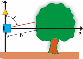
Figure 1 shows the LiDAR data acquisition method based on Rosell et al. (Reference Rosell, Llorens, Sanz, Arnó, Ribes-Dasi and Masip2009), which inspired the method used in this study. In this method, D is the distance between the sensor and the obstacle and j is the measurement angle in the vertical plane, from 0 to 180°. Distance measurements were collected in angular steps of 1° along the vertical plane. The third dimension (Y axis) of the data (not represented on the figure) is acquired by the movement of the MTLS along the alleys of the crop. The RTK-GNSS receiver is used to collect the sensor position and later transfer the coordinates to each laser beam impact.
X, Z measurement plane. Measurement of the distance D on the j angle. Triangle represents the RTK-GNSS and the square the LiDAR

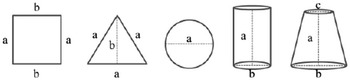
Six different objects were scanned with the system (Figure 2). The objects were a square (1×1 m), an equilateral triangle (1 m of side), a circle (1 m of diameter), two different cylinders (0.2 and 0.3 m of diameter and height of 0.83 m and 0.80 m, respectively) and truncated cone (0.64 m of height, bottom diameter of 0.45 m and top diameter of 0.31 m).
‘a’, ‘b’ and ‘c’ dimensions of the objects

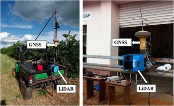
Two tests were carried out. In the first one, a platform running over a rail carried the developed MTLS system, reducing the rotation of the sensor along its three axes. Whereas, in the second test, the MTLS system was attached to an all-terrain vehicle (ATV) using a customized structure that ran over a leveled lawn (Figure 3). In both tests, five replications were made for each object, accounting thirty collections for each scenario.
MTLS mounted on an all-terrain vehicle (left) and mounted on a platform running over a rail (right)

The collected data was processed by transforming the polar coordinates (angles and distances) into rectangular coordinates (x, y and z) representing each laser beam impact. Further, each point was georeferenced using the GNSS data. R software (Free Software Foundation, Boston, USA) was used for this transformation. The software CloudCompare 2.6.2 (GPL software, Grenoble, France) was used for visualizing the 3D point cloud.
To evaluate the accuracy of the MTLS, the volume of the cylinders and truncated cone and the area of the circle, triangle and square were calculated. These geometric parameters were calculated directly from the point cloud by using the ‘point picking’ tool available in the CloudCompare 2.6.2 for measuring the dimensions of the objects.
Statistical analyses were made using R software. The t-student paired test was used to evaluate if there was significant difference (α=0.05) between the area/volume estimated by the use of MTLS and the real dimensions of the objects. The difference between the use of the rail and the ATV was also evaluated. The errors on the area and volume estimations were computed.
Results and Discussion
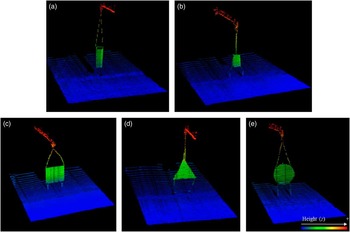
Figure 4 shows the shapes of each object scanned by the MTLS mounted on the ATV. Results seem visually coherent.
Point cloud of the scanned objects. (a) cylinder, (b) truncated cone, (c) square, (d) triangle, (e) circle

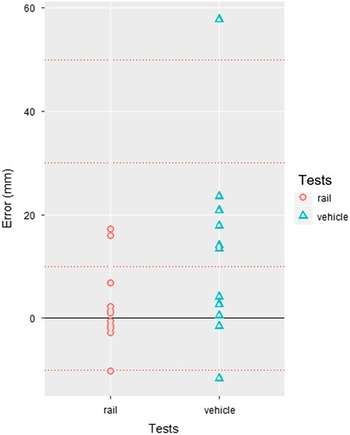
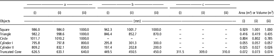
The object dimensions obtained by the two tests are viewed in Table 1. It is possible to observe that for both tests (MTLS mounted on an ATV and running over a rail) the dimensions measured by the point cloud and the actual dimensions are very similar. The overall (absolute average error) difference between estimated and real dimensions was 5.3 mm for rail collection and 14.3 mm for ATV, with the lowest error being 0.5 mm (‘b’ dimension from truncated cone with MTLS running over a rail) and largest error being 57.7 mm (‘b’ dimension from square with MTLS mounted on an ATV). Figure 5 shows the distribution of the errors on the ‘a’, ‘b’ and ‘c’ dimensions.
Dot plot for errors of the dimensions obtained from the point cloud

Object parameters (dimensions a,b,c, areas and volumes) measured by a mobile terrestrial laser scanner compared to actual values

(i), laser scanner mounted on an ATV; (ii) laser scanner mounted on a platform running over a rail; (iii) actual dimension; Area: surface area of square, triangle and circle; Volume: volume of cylinders and truncated cone; a, b and c (Figure 2)
The maximum difference between actual and estimated area of the objects was 0.071 m2 (square area with MTLS mounted on an ATV), which represents 7.1% of the square area, and the minimum 0.001 m2 (square area with MTLS mounted on a platform running over a rail), 0.1% of the square area (Table 1).
For agriculture purpose, one of the uses of the MTLS would be to guide the application of inputs based on the canopy volume of the crop. Therefore, the accuracy of the volume information obtained by the LiDAR system is crucial to sustain the application of this technology. The maximum difference between the actual volume of the 3D objects and the estimated volume was 0.0017 m3 (volume of cylinder I with MTLS mounted on an ATV), which represents 2.9% of the cylinder I volume. Moreover, the lowest difference was 0.0003 m3 (volume of cylinder I with MTLS running over a rail), 0.6% of the cylinder I volume.
Besides that, it is possible to verify that, as expected, the accuracy of the measurements using the ATV was slightly worse than the MTLS running over a rail. It probably occurred because the rail reduced the movements in the three axes of the sensor (pitch, yaw and roll) during the data acquisition. However, the statistical test did not accuse difference between the real dimensions and the two different tests estimated dimensions (rail and ATV). We also did not found statistical difference between the two tests, with a 5% significance.
The main source of errors in such measurements are the error in the measurements of the LiDAR sensor (±5 mm), RTK-GNSS (±10 mm) and the movement of the sensor along its three axis. Considering these error sources, the results obtained in this study showed acceptable errors in the point cloud, from an agriculturally applied point of view.
Conclusions
The errors involved in the data acquisition by a MTLS have many different sources, such as the LiDAR sensor measurement error, the movements of the sensor during operation, GNSS signal and others. However, these errors did not affect significantly the estimation of geometric parameters during our tests. The results from this study indicates that MTLS are satisfactory tools for precision agriculture uses. However, these results might differ in terrains with more irregularities. In such situations, an inertial measurement unit could be used to correct the errors caused by the movement of the LiDAR sensor.
Acknowledgements
The authors would like to thank to the São Paulo Research Foundation (FAPESP – Process number: 2016/16100-2).