I. INTRODUCTION
Fused deposition modeling (FDM) 3D printing is an additive manufacturing technique used to fabricate polymer objects directly from computer modeled designs. The technology offers an inexpensive and efficient technique to produce customized parts with intricate geometries using a simple printing process. Despite a wide range of potential applications, FDM has been mostly limited to the fabrication of prototype items with no inherent functionality. This limitation has restricted FDM technology innovation and advancement within the 3D printing and manufacturing industries, as it prevents fabrication of complete functional systems. The goal of this work is to utilize a method for improving the functionality of FDM printing through creation of printable composite materials to demonstrate broadened application of the technology through 3D printing of radiation shielding components.
The primary reason for the constraint in FDM technology is the limited choice of materials available for printing. Thermoplastic polymers are primarily used for their thermal processability, which is necessitated by the FDM extrusion process.Reference Turner, Strong and Gold1 Very few commercially available thermoplastic polymers provide functional characteristics beyond printability. For FDM 3D printing to progress to more useful and novel applications and compete with traditional manufacturing techniques, research must focus on imparting functionality into the materials used in the process.
One method used to achieve this goal is creation of thermoplastic polymer composites. This technique involves mixing additives which have desired functional characteristics into a thermoplastic polymer matrix. The resulting combination continues to operate as a printable material while simultaneously providing a desired functional attribute. This technique has gained popularity recently as researchers work toward developing new materials to broaden the application of FDM 3D printing. Functional attributes such as electrical conductivity,Reference Leigh, Bradley, Purssell, Billson and Hutchings2–Reference Christ, Aliheidari, Ameli and Potschke4 magnetism,Reference De Santis, Gloria, Russo, Ronca, D’Amora, Negri, Ronca and Ambrosio5,Reference Bollig, Hilpisch, Mowry and Nelsion-Cheeseman6 and bacterial resistanceReference Sandler, Salmela, Fallarero, Rosling, Khajeheian, Kolakovic, Genina, Nyman and Vuorela7–Reference Teo, Ong, Chong, Zhang, Lu, Moochhala, Ho and Teoh9 have been demonstrated in FDM composite materials.
Neutron radiation shielding is one characteristic, which has not yet been studied in relation to FDM materials. This functionality has potential to open the FDM printing process to aerospace component manufacture, where radiation is a significant hazard. Neutrons are one of the most severe forms of ionizing radiation, resulting in material structure degradation, electrical component destruction, and biological tissue damage.Reference Kennedy10,Reference Stiegler and Mansur11 Creating FDM materials with neutron radiation shielding properties would enable aerospace component manufacturers to fabricate complete functional systems from FDM printers and take advantage of the benefits of FDM technology.
In this work, a neutron shielding material was fabricated for use in standard FDM systems. Boron nitride particles were added to an acrylonitrile butadiene styrene (ABS) polymer matrix to form a radiation shielding composite. Particle dispersion, material uniformity, thermal, and mechanical properties were analyzed to assess the effect of the boron nitride additive and to ensure fabrication of a material compatible with standard FDM printers. Neutron attenuation was then tested to quantify the functionality of the new material composite and determine its potential for application in the aerospace industry.
II. MATERIALS AND EXPERIMENTAL PROCEDURES
A. Materials
ABS is one of the most prevalent thermoplastic polymers used in FDM printing.12–Reference Tanikella, Wittbrodt and Pearce14 This popularity is due to a variety of factors, including low cost, good material strength, and ease of printability. For these reasons, ABS was chosen as the composite matrix material in this work. The polymer was purchased in pellet form from IC3D Industries, Columbus, Ohio (Part # ABS3PELNAT).
Boron nitride has been demonstrated to be an effective additive in blocking neutron radiation.Reference Kim, Lee, Uhm and Miller15,Reference Harrison, Weaver, Bertelsen, Burgett, Hertel and Grulke16 This is a result of the high neutron capture cross section of boron, an indicator of the ability of an element to block and absorb incident neutrons. Boron has a value of approximately 760 b, the 10th highest of all elements.17 Boron nitride particles were purchased from US Research Nanomaterials, Inc., Houston, Texas (Stock # US2019). Particles were greater than 99.8% purity with hexagonal crystallographic structure and a primary particle size of 70–80 nm.
B. Fabrication of the 3D FDM boron nitride composite
A solution processing technique was used to fabricate the composite material. First, ABS pellets were dissolved in acetone. 100 g of ABS pellets were added to 400 mL acetone, left to react for 24 h, and mixed mechanically to form a homogenous polymer solution. Boron nitride powder was added to the solution, mixed, and sonicated to evenly disperse the particles. Three concentrations were tested: 5% (5.27 g), 10% (11.11 g), and 20% (25.0 g) by weight, equating to 2.69%, 5.50%, and 11.58% by volume, respectively.
The solution mixture was then poured onto a glass plate for solvent evaporation. Then, the dried composite was cut into small pieces, approximately 5 mm × 5 mm, which were further dried at 80 °C to remove any residual solvent. These dried pieces were then fed into a hammer mill grinder to form a composite powder. The ground powder was stored at 60 °C for 7 days, and agitated daily to provide sufficient time to ensure that all remaining solvent was removed from the material.
For use in standard FDM systems, the composite material was extruded into the filament form. To accomplish this, a desktop filament single-screw extrusion system was used. To begin the extrusion process, the temperature controller of the extrusion system with 1.75 mm nozzle was set to 190 °C. The composite powder was fed into the system hopper while a screw pushed the powder toward the nozzle. As the material traveled through the barrel, the mixture was heated to a molten state, pressurized, and extruded through the nozzle. The filament was air cooled and wound onto a spool using an automated guide system. The result of this process was a 1.75 mm boron nitride composite filament that can be used in any standard FDM system.
C. Characterization
Cross sections of the filament were set in EpoThin2 epoxy resin and well-polished for imaging. Using a Zeiss Auriga FESEM (Carl Zeiss AG, Oberkochen, Germany), scanning electron microscopy (SEM) and energy dispersive X-ray spectroscopy (EDS) were performed to analyze particle dispersion and elemental distribution.
Raman microscopy was used to obtain a Raman spectrum of each composite concentration. Samples of the filament were imaged under a 10× objective and exposed to a 785-nm laser using a Horiba XploRA Raman system (Horiba, Ltd., Kyoto, Japan). Spectra were collected and plotted using LabSpec 6 software (Horiba, Ltd., Kyoto, Japan). Pure boron nitride particles were also characterized, and the obtained spectra were compared to literature values.
Thermal degradation onset points and residual mass percentages were calculated using a TA Q500 (TA Instruments, New Castle, Delaware). Titanium hang down pans were loaded with 10 mg samples, and at least five samples of each concentration were tested. Heat rate was ramped at 10 °C per minute from 30 °C to 600 °C under a nitrogen environment at a 60 mL/min flow rate.
Glass transition temperatures were analyzed using a TA Instruments Q200 (TA Instruments, New Castle, Delaware) for differential scanning calorimetry (DSC) measurements. A 5 mg sample of each material was prepared and heated from 35 to 180 °C at a ramp rate of 10 °C per minute. The resulting curve of temperature versus heat flow was analyzed for glass transition temperature using half heat flow extrapolation calculation.
For mechanical and neutron attenuation testing, appropriate samples were printed from the boron nitride composite filament using a Fusion3 F306 system (Fusion3, Greensboro, North Carolina). The sample dimensions were 65.3 × 65.3 × 3.4 mm at 100% infill and +45°/−45° raster pattern. The print head temperature was 245 °C printing on a heated bed set at 110 °C.
ASTM D638 specimens were cut using a water jet from the printed 3D part for mechanical testing. The specimen dimensions adhered to guidelines for type V samples. An Instron 5900R material test frame (Instron, Norwood, Massachusetts) with 5 kN load cell was used to perform mechanical testing based on ASTM D638 test conditions, which includes 1 mm/min speed of testing and 25 mm gauge length. Tensile stress was measured using a load cell and plotted as a function of percent strain, determined from the test-frame crosshead movement. The slope of the stress–strain curve in the elastic zone was calculated to determine the modulus of elasticity.
Dynamic mechanical analysis (DMA) was used to study mechanical properties of the composites at various temperatures. DMA tests were performed using a Perkin Elmer DMA 8000 system (PerkinElmer, Waltham, Massachusetts). The samples were cut from printed pieces in rectangular beams with dimensions 50.5 × 12.6 × 3.6 mm. Dual cantilever testing was performed at a frequency of 0.05 Hz with a temperature ramp from 30 to 150 °C. The storage modulus values were analyzed.
To test the neutron attenuation properties of the 3D-printed composite materials, the samples were exposed to a neutron particle beam and a detector measured incident neutrons before and after neutron exposure. The printed parts were moved into a collimated neutron beam between BF3 detectors and the reactor using a carrier system. The beam consisted of thermal neutrons with an average energy of 0.025 eV. Counts were taken in multiple spots on each sample. The counting times were 30 s, to ensure that a minimum of 15,000 counts from neutrons will penetrate the sample. A ‘blank’ and a ‘black’ sample with 0% and 100% effective shielding, respectively, were also used to normalize the measured data. These tests were performed at the Breazeale Nuclear Reactor at Pennsylvania State University Radiation Science and Engineering Center.
III. RESULTS AND DISCUSSION
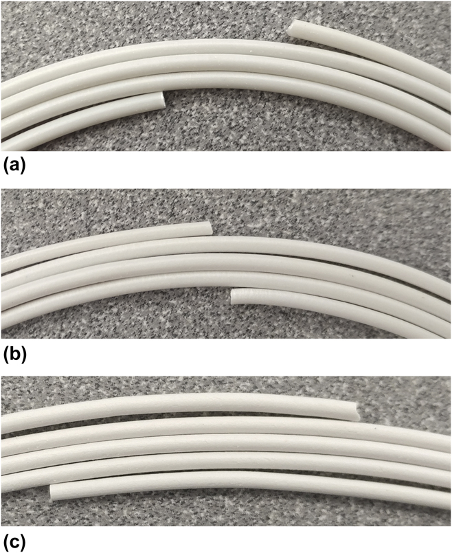
Figure 1 shows the boron nitride composite filaments of 5% by weight concentration in Fig. 1(a), 10% in Fig. 1(b), and 20% in Fig. 1(c). The particles in the composite appear to be consistently distributed with a smooth surface finish at 5% and 10% concentrations, and slight surface roughness at 20%. The diameter of the 5% composite are in the range of 1.79 ± 0.06 mm, the 10% composite are in the range of 1.77 ± 0.04 mm, and 20% composite in the range of 1.76 ± 0.08 mm. These values fall well within the necessary tolerances for successful FDM printing. Higher concentrations were also tested, but filament extrusion resulted in poor quality material, porous microstructure, severely weakened mechanical properties, and inconsistent printability. 20% addition of BN by weight was determined to be the threshold value for these materials and this method of composite fabrication.
Boron nitride composite filament, (a) 5%, (b) 10%, and (c) 20%.
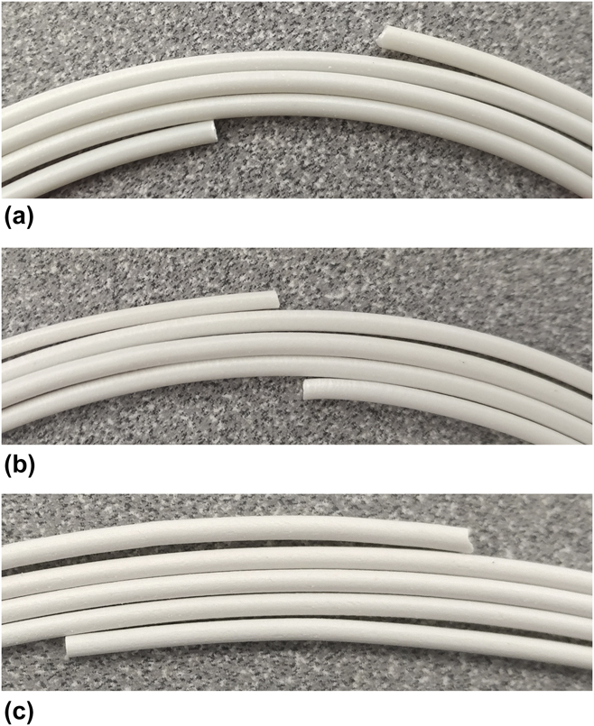
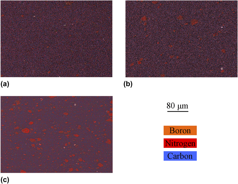
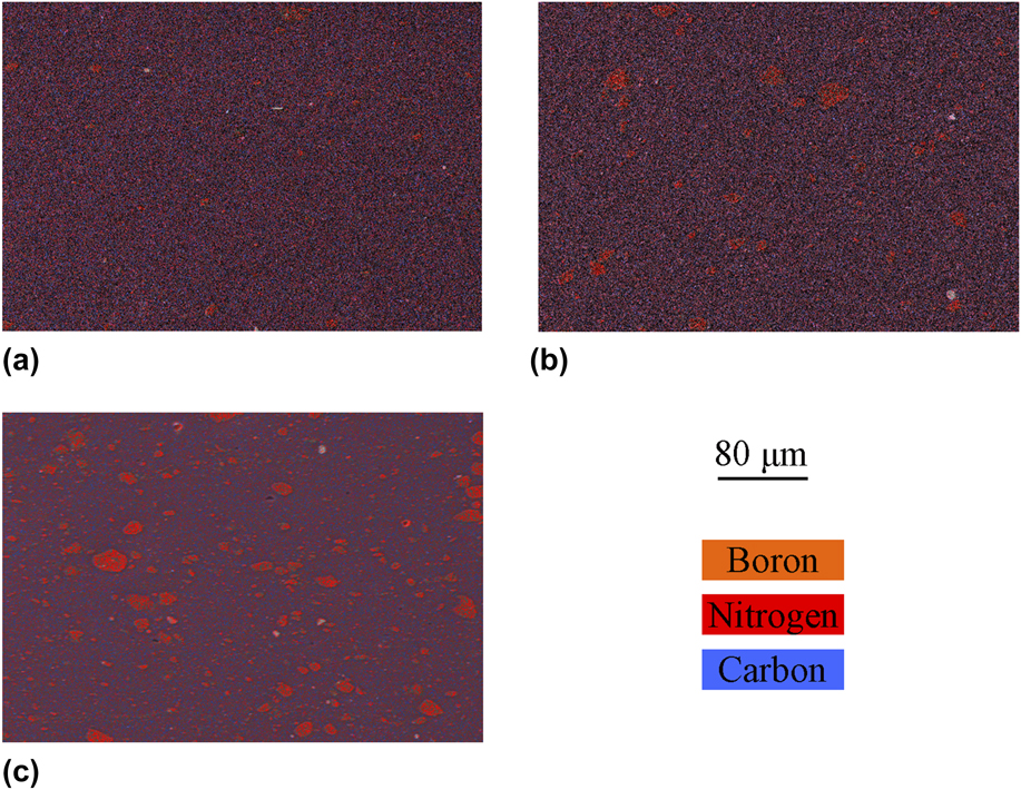
Figure 2 shows representative SEM–EDS images of the boron nitride composite at 250× magnification, namely 5% by weight concentration in Fig. 2(a), 10% by weight concentration in Fig. 2(b), and 20% by weight concentration in Fig. 2(c). Differences in color/contrast show that the particles are well-dispersed, with particle sizes ranging from nanoscale primary particles to tens of microns for secondary particles. This distribution mimics the particle imaging from pure BN powder, and the absence of larger agglomerates suggests that the mixing protocol was able to evenly combine the boron nitride additive and polymer.
SEM/EDS map of boron nitride composite filament, (a) 5%, (b) 10%, and (c) 20%.
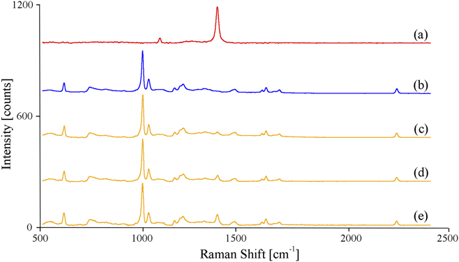
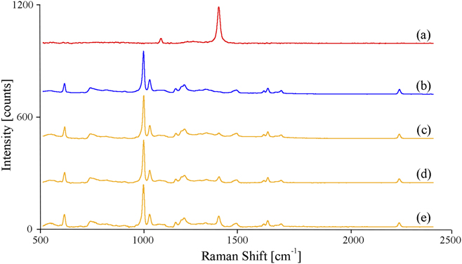
Raman spectroscopy was used to verify the presence of boron nitride within the composite. Boron nitride contains a distinct inelastic scattering signal. The resulting spectra of pure BN particles, pure ABS, and 5, 10, and 20% BN composites are shown in Fig. 3. For pure BN, a distinct peak is visible at 1364 cm−1, which agrees with the reported values in the literature.Reference Reich, Ferrari, Arenal, Loiseau, Bello and Robertson18 This peak is due to the vibrational bond between boron and nitride in their hexagonal lattice. The measurement of the composite materials also reveals the pure ABS spectra, which agrees with the reported value in the literature,Reference Colthup, Daly and Wiberley19 in addition to boron nitride 1364 cm−1 peak. This indicates that boron nitride as an additive is present in the composite and does not interfere with any bonding between monomers, as all vibrational modes are also present in the spectra. Furthermore, at higher additive percentages, the peak becomes more pronounced, as expected because of higher particle concentration.
Raman spectra of (a) boron nitride particles, (b) ABS, (c) 5%, (d) 10%, and (e) 20% composite filament.
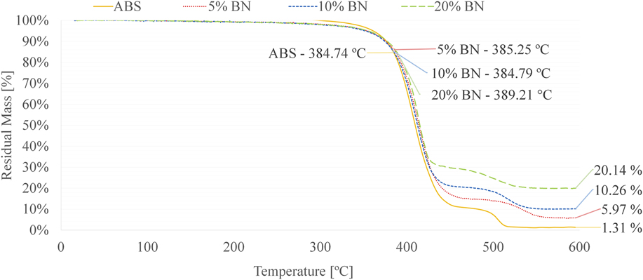
Next, the dispersion uniformity was studied in TGA plots of ABS and each composite in Fig. 4. At a temperature of 533 °C, ABS reaches a minimum residual mass percentage of approximately 1%. The 5% boron nitride composite samples show an average residual mass percentage of 6.02 ± 0.07%, the 10% samples show an average residual mass percentage of 10.23 ± 0.05%, and the 20% samples show 20.12 ± 0.13% residual mass. This remaining mass is primarily attributed to the boron nitride additive, as ABS thermally degrades at a temperature below boron nitride particles. Each of the measurements closely matches the intended 5, 10, or 20% by weight addition. The measurements, which were taken at several time-points throughout the extrusion process, resulted in small standard errors of less than 1%, which suggests that the boron nitride additive is evenly dispersed throughout the extruded filament.
TGA plot of ABS and boron nitride composites.
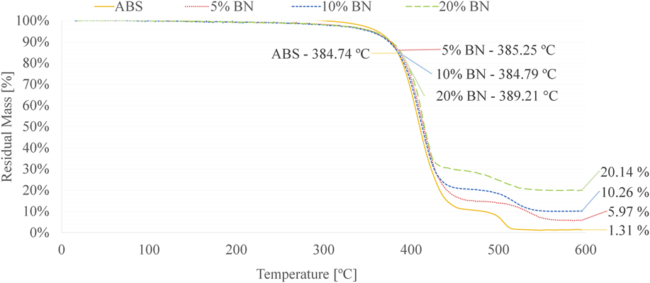
Thermal onset point was also determined for each composite from TGA plots. The onset point is the temperature at which thermal degradation begins to occur, calculated by extrapolation of the predegradation and postdegradation point slopes, and used to assess thermal stability of a material at high temperatures. The calculations from several samples showed an ABS onset point of 385 ± 1.13 °C. The boron nitride composites were compared to this value to ensure that the inclusion of additive did not significantly lower this degradation point. The 5% boron nitride composite onset point averaged 386 ± 0.48 °C compared to 384 ± 1.15 °C for the 10% composite and 391 ± 2.01 °C for the 20% composite. The values of 5% and 10% composites closely match that of the pure ABS, indicating that these additive percentages do not significantly affect the thermal degradation onset point. The 20% composite displayed a slightly larger thermal onset point, indicating that the larger additive percentages may prevent thermal degradation until higher temperatures are reached.
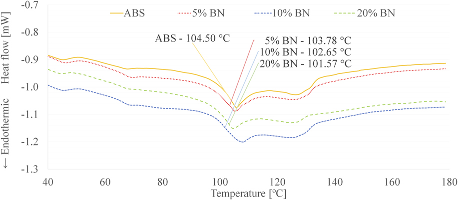
To further investigate the thermal properties of these composites, DSC analysis was performed to measure glass transition temperature of the composite materials. This value related to the temperature at which a polymer begins to experience chain movement due to an increase in thermal energy, and is an important consideration for 3D printability. Figure 5 shows the DSC plot of ABS in comparison to 5, 10, and 20% boron nitride composites. The pure ABS has an average glass transition temperature of 104.21 ± 0.11 °C. This value agrees with the value reported in the literature of 105 °C.Reference Mark20 The 5% boron nitride composite samples average a transition temperature of 103.45 ± 0.38 °C, the 10% composite samples average 102.94 ± 0.48 °C, and the 20% composite samples average 102.23 ± 0.51 °C. The slightly decreased values of the boron nitride samples compared to ABS indicate that the additive only minimally affects thermal properties. The shift is likely a result of increased free volume in the material, due to the addition of boron nitride particles, resulting in a higher degree of freedom for polymer chain motion at a lower temperature during heating. However, the shift is not extreme and the 3D printability of the material will not be significantly affected due to this thermal change.
DSC plot of ABS and boron nitride composites.
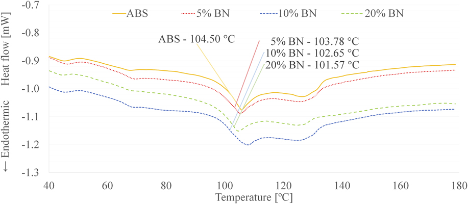
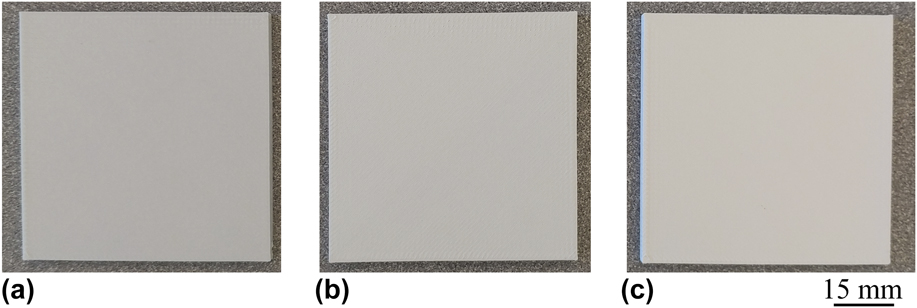
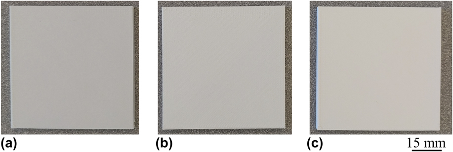
Figure 6 shows images of sample panels 3D printed from pure ABS and boron nitride composite filaments. All concentrations of the composite printed without any problem using the same parameters as pure ABS printing. The print time for each 3D printed panel was about 24 min. The first layer adhesion showed no deterioration compared to pure ABS printing. The high quality surface finish of all 3D prints demonstrated its versatile printing capability.
Boron nitride composite printed panels, (a) 5%, (b) 10%, and (c) 20%.
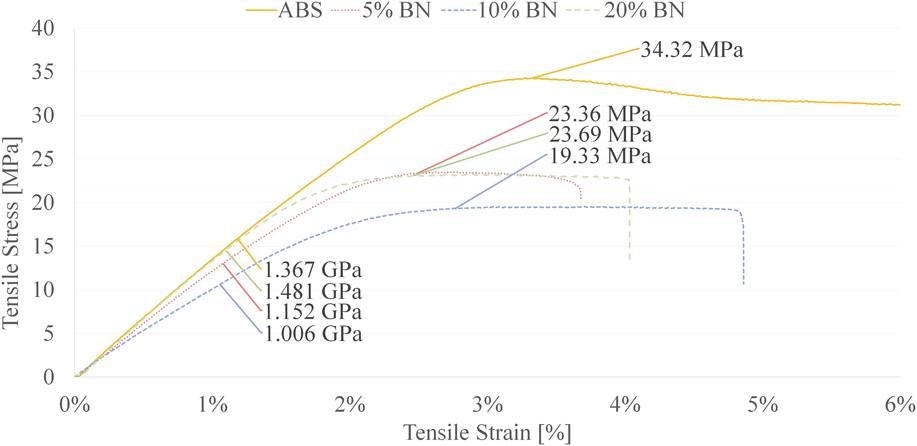
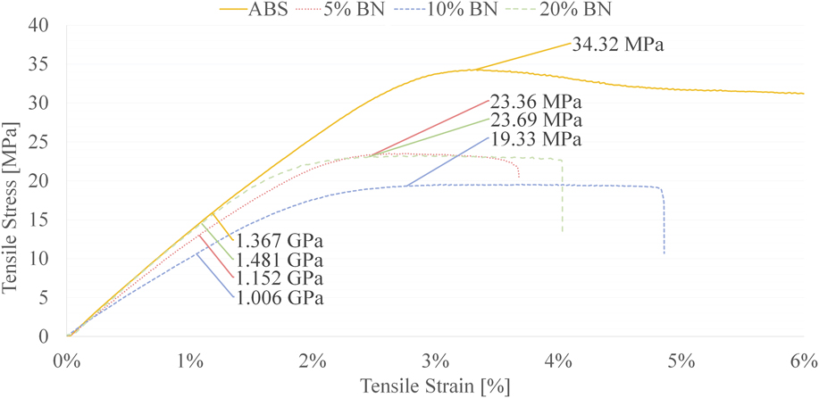
The mechanical testing of ABS and composite samples were then measured and compared to determine the effect of boron nitride additive on polymer strength. Figure 7 shows the stress–strain curves of ABS and boron nitride composites from ASTM D638 tensile tests. The variations in stress–strain curves of material concentration are apparent. The ABS shows the highest tensile stress of 34.01 ± 0.55 MPa. 5% boron nitride samples have an average tensile stress of 23.85 ± 0.62 MPa, 10% samples average 18.86 ± 0.91 MPa, and 20% samples average 23.16 ± 1.16 MPa. These results indicate that the addition of boron nitride does degrade the ultimate tensile stress of the polymer, with 10% affected the most. Similarly, ABS shows a superior modulus of elasticity at 1.365 ± 0.05 GPa, compared to 5% and 10% boron nitride composite samples at 1.179 ± 0.07 GPa and 0.979 ± 0.06 GPa, respectively. The 20% boron nitride composite shows an enhanced modulus at 1.420 ± 0.06 GPa. These results indicate that smaller additive percentages influence the elasticity of the composites toward softer characteristics, but higher concentrations may stiffen the 3D-printed material.
Tensile stress–strain plot of ABS and boron nitride composites.
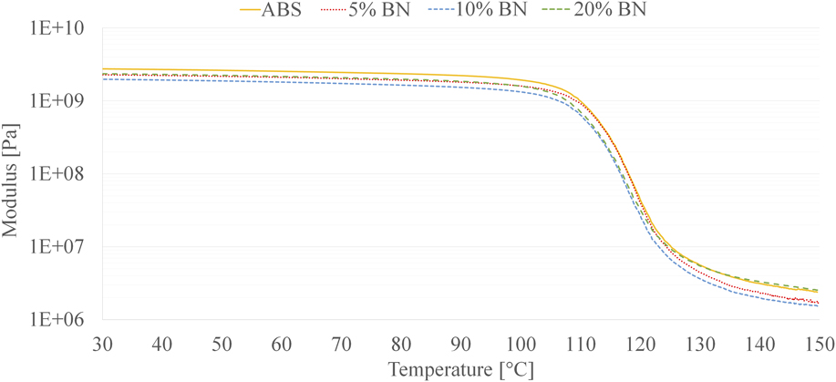
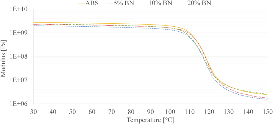
Next, the samples were tested to evaluate the storage modulus of the 3D composite as a function of temperature using DMA. Figure 8 shows the DMA plot of ABS and boron nitride composites. The curves show that ABS and the composites show nearly identical mechanical behavior. The ABS maintains a glassy region modulus of 2.67 GPa from room temperature up to ABS glass transition temperature of around 105 °C. After reaching glass transition, the modulus falls to 2.15 MPa in its rubbery region, around 140 °C. Similarly, the boron nitride composites storage moduli range from 2.00 to 2.54 GPa, up to 105 °C, falling to a minimum of 1.31 MPa at 140 °C. These mechanical analysis results may be due to the interactions between the additive and the polymer chains. Any additive percentage may interfere with polymer bonding, thereby degrading the ultimate tensile stress. The addition of small percentages of additives results in slight decrease in modulus values, which may be due to the addition of free volume and decrease in material stiffness in the 3D print. At higher additive percentages, the greater particle concentration is expected to restrict polymer chain motion, thus increasing the stiffness and modulus of elasticity. Despite the altered characteristics due to the additives, all filaments were printed on a standard FDM printer without any problem. The slight variations in the material strength did not affect the printability of the composite filaments.
DMA plot of ABS and boron nitride composites.
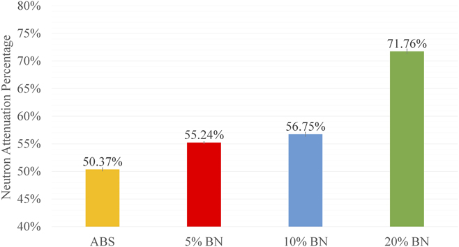
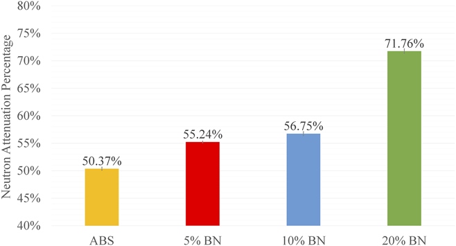
Lastly, functional assessment was performed to determine the radiation shielding characteristics of pure 3D-printed ABS and 3D-printed composites. Figure 9 shows the attenuation percentage data for ABS and boron nitride composites. ABS shows 50.37% attenuation, indicating approximately half of the neutrons passed through the shielding panel. This was expected, as ABS contains a large amount of hydrogen atoms, providing adequate shielding properties at high concentrations. 5% and 10% boron nitride composites show slightly enhanced attenuation, of around 55–57%. 20% boron nitride 3D-printed composite showed a significant increase in attenuation characteristics by blocking 71.76% of incident neutrons.
Neutron attenuation of ABS and boron nitride composites.
Using the following equation, attenuation coefficients were calculated to further understand radiation shielding functionality,
 $$I = {I_0}{{\rm{e}}^{ - \mu t}}\quad ,$$
where I is the neutron count after passing through the panel, I 0 is the initial neutron count, μ is the attenuation coefficient, and t is the panel thickness. I and I 0 values were taken from experimental results. The calculations result in an attenuation coefficient of 2.044 for ABS, 2.405 for 5% boron nitride composite, 2.487 for 10% boron nitride composite, and 3.697 for 20% boron nitride composite. These values further show that the higher percentage boron nitride in 3D composite materials resulted in strong radiation shielding.
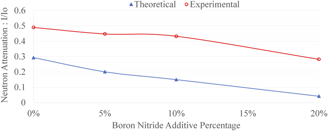
To assess validity of the attenuation testing, theoretical calculations of radiation shielding ability of boron nitride were compared to the experimental results. Total atomic density of carbon, hydrogen, nitrogen, and boron atoms in each panel were used to calculate macroscopic neutron capture cross section Σ (cm−1). The theoretical shielding ratio was then determined using a formula similar to the attenuation factor equation:
 $$I = {I_0}{{\rm{e}}^{ - \Sigma t}}\quad .$$
Figure 10 shows the results from these calculations for boron nitride composites. The general trend of the experimental and theoretical data match very well, which suggests the accuracy of the experimental radiation measurement with boron nitride composites. The discrepancy in magnitude of attenuation may be due to the theoretical assumption of 100% neutron absorption, ideal atomic capture cross section and dispersion.
Comparison of experimental neutron attenuation results with theoretical calculations.

IV. CONCLUSION
In summary, in this work, we have shown an effective method for producing new functional FDM 3D printing materials with radiation shielding capabilities. The solution mixing and desktop extrusion processes were used successfully to fabricate boron nitride composite materials in the filament form for use in any standard FDM system. The microscopic and thermogravimetric analysis confirmed an even dispersion of boron nitride particles in an ABS polymer matrix. The thermal analysis further confirmed that thermal properties only changed minimally to the pure ABS polymer. The mechanical analysis revealed some variation in strength of the polymer, compared to the composites, but 3D printability was not affected, allowing use of the composite in any standard FDM system.
Functional testing for neutron attenuation showed a significant increase in the radiation shielding characteristics of 3D-printed composite with boron nitride. The neutron radiation shielding capability was enhanced from 50% in pure ABS samples up to 72% in 20% boron nitride composites, which can be valuable to reduce damage from neutron radiation sources for aerospace applications.
In conclusion, the addition of boron nitride particles in the ABS polymer was shown in this work to be an effective technique for additive manufacturing of neutron radiation shields. The ability to manufacture these functional FDM materials is expected to assist the additive manufacturing community to move beyond just “form-and-fit” prototyping into the production of complete end-use parts, for example, in aerospace component manufacturing. In future studies, other material composites will be tested to provide even higher neutron shielding capacities, thereby allowing FDM to become a viable technology for the production of critical radiation shielding components.
ACKNOWLEDGMENTS
This work was performed at the Joint School of Nanoscience and Nanoengineering, a member of the Southeastern Nanotechnology Infrastructure Corridor (SENIC) and National Nanotechnology Coordinated Infrastructure (NNCI), which is supported by the National Science Foundation (Grant No. ECCS-1542174).