





Introduction
The transition towards sustainable material systems has intensified research into biologically derived membranes, such as bioplastics, cellulose, and mycelium-based materials, as alternatives to fossil based polymers (Design Farm Berlin 2023; Madusanka et al. Reference Madusanka, Udayanga, Nilmini, Rajapaksha, Hewawasam, Manamgoda and Vasco-Correa2024; Vandelook et al. Reference Vandelook, Elsacker, VanWylick, Laet and Peeters2021;Weißensee Kunsthochschule Berlin 2023). Due to their low weight, biodegradability, and renewable origin, such materials are increasingly discussed in the context of mechanically loaded lightweight structures and biodesign applications (Appels et al. Reference Appels, Camere, Montalti, Karana, Jansen, Dijksterhuis, Krijgsheld and Wösten2019; Vandelook et al. Reference Vandelook, Elsacker, VanWylick, Laet and Peeters2021). However, their use in tension-dominated systems remains limited since biologically derived membranes typically exhibit low fracture resistance and unstable crack propagation under tensile loading (Appels et al. Reference Appels, Camere, Montalti, Karana, Jansen, Dijksterhuis, Krijgsheld and Wösten2019; Jones et al. Reference Jones, Gandia, John and Bismarck2021).
Cellulose, often used for membrane-like tissues, is one of the most abundant and structurally versatile biopolymers and is widely established as a sustainable engineering material due to its hierarchical organization and favourable mechanical properties (Klemm et al. Reference Klemm, Heublein, Fink and Bohn2005). Additionally, fungal mycelium-based materials, also manufacturable in sheet-like manner, have emerged as promising candidates for circular material systems since they can be cultivated from low value biomass with comparatively low energy input (Appels et al. Reference Appels, Camere, Montalti, Karana, Jansen, Dijksterhuis, Krijgsheld and Wösten2019; Meyer et al. Reference Meyer, Basenko, Philipp Benz, Braus, Caddick, Csukai, De Vries, Endy, Frisvad and Gunde-Cimerman2020). Reviews further highlight their potential as systems with tunable stiffness and biodegradability (Cerimi et al. Reference Cerimi, Akkaya, Pohl, Schmidt and Neubauer2019; Vandelook et al. Reference Vandelook, Elsacker, VanWylick, Laet and Peeters2021). Current research and commercial applications primarily focus on mycelium-based leather substitutes and surface materials. Recent developments in densification, crosslinking, plasticization, and lamination have improved tensile properties (Benetti et al. Reference Benetti, Conti and Dimitriadis2025; Vandelook et al. Reference Vandelook, Elsacker, VanWylick, Laet and Peeters2021), yet the mechanical behaviour of biologically derived membranes is still mainly addressed through material processing rather than structural design.
Among various fungal systems, Fomes fomentarius has attracted attention due to its hierarchical fibrous microstructure, low density, and tunable mechanical response. Chen et al. demonstrated both the extrusion-based processability of fungal material (Chen et al. Reference Chen, Abdullayev, Bekheet, Schmidt, Regler, Pohl, Vakifahmetoglu, Czasny, Kamm and Meyer2021) and the feasibility of thermoplastic reinforcement on mycelium mats, resulting in improved tensile stiffness and strength (Chen et al. Reference Chen, Klemm, Dönitz, Ou, Schmidt, Fleck, Simon and Völlmecke2024). However, the latter approach was limited to linear filament deposition. The use of topology controlled and performance-optimized reinforcement to tailor mechanical stiffness, ultimate tensile strength (UTS), and fracture behaviour remains unexplored.
Extrusion-based 3D printing technologies, such as Fused Filament Fabrication (FFF), enable geometry-driven and performance-optimized topologies through precise and controlled filament deposition on compliant membranes. Previous studies on additively manufactured polymers have shown that raster orientation and topological design significantly influence stiffness, strength, and fracture behaviour (Lorenzo-Bañuelos et al. Reference Lorenzo-Bañuelos, Díaz and Cuesta2020; McLouth et al. Reference McLouth, Severino, Adams, Patel and Zaldivar2017; Torrado and Roberson Reference Torrado and Roberson2016; Zhang et al. Reference Zhang, Choi and Ki Moon2021). Related work on textile membranes further demonstrate that mechanical response is strongly governed by membrane morphology and interfacial adhesion (Gorlachova and Mahltig Reference Gorlachova and Mahltig2021; Koch et al. Reference Koch, Schmelzeisen and Gries2021; Loh et al. Reference Loh, Sotayo and Pei2021). Yet, these systems are typically based on synthetic, non-recyclable composites.
Within this context, the combination of bio-based membrane materials with performance-driven reinforcement strategies becomes apparent. Figure 1 illustrates a potential architectural application of a reinforced biomembrane in a pavilion demonstrator with distinct reinforcement topologies.
Pavilion demonstrator for distinct mechanics-driven reinforcement topologies on biologically derived membrane.

Reinforcement topologies can be distinguished based on their fundamentally different deformation mechanisms as reported for architected lattice materials. Stretching-dominated lattice systems (diamond lattices) are known to increase stiffness through axial force transfer, but often exhibit localized stress concentration and abrupt failure due to the concentration of tensile forces within individual load carrying members (Choukir and Singh Reference Choukir and Singh2023; Deshpande et al. Reference Deshpande, Fleck and Ashby2001). In contrast, re-entrant architectures promote bending-influenced deformation, stress redistribution, and progressive mechanical response through geometric reconfiguration of curved ligaments (Choi and Park Reference Choi and Park2023; Ghalehney et al. Reference Ghalehney, Sahel and Gharehbaghi2024; Nugroho et al. Reference Nugroho, Dong and Pramanik2026). These characteristics can be utilized to suit certain loading condition.
However, while topology-controlled additive reinforcement offers a promising route to overcome the mechanical limitations of biologically derived membranes, the environmental implications of such reinforcement strategies remain unclear. As mentioned afore, bio-based membranes such as cellulose and fungal mycelium are commonly discussed in relation to renewable origin, biodegradability, and circular material strategies (Appels et al. Reference Appels, Camere, Montalti, Karana, Jansen, Dijksterhuis, Krijgsheld and Wösten2019; Klemm et al. Reference Klemm, Heublein, Fink and Bohn2005; Meyer et al. Reference Meyer, Basenko, Philipp Benz, Braus, Caddick, Csukai, De Vries, Endy, Frisvad and Gunde-Cimerman2020; Vandelook et al. Reference Vandelook, Elsacker, VanWylick, Laet and Peeters2021). Yet, these advantages do not automatically imply that reinforced bio-based composite systems also have a low environmental burden. In additively reinforced membrane systems, additional biopolymer reinforcement material, printing electricity, and membrane-specific preparation routes may contribute to the specimen-level global warming potential (GWP). Therefore, topology-controlled reinforcement should not only be evaluated in terms of mechanical performance, but also with respect to its environmental implications.
Previous Life Cycle Assessment (LCA) studies on fungal-based composites and sheet-like mycelium products have shown that cultivation route, drying, post-treatment, and electricity demand can strongly influence environmental performance (Bahua et al. Reference Bahua, Wijayanti, Putra, Ariyani, Isharyadi, Nuha and Paminto2024; Stelzer et al. Reference Stelzer, Hoberg, Bach, Schmidt, Pfeiffer, Meyer and Finkbeiner2021). These studies indicate that the environmental performance of mycelium-based and bio-based materials depends not only on biological origin or biodegradability, but also on processing intensity, energy demand (Volk et al. Reference Volk, Schröter, Saeidi, Steffl, Javadian, Hebel and Schultmann2024; Weinland et al. Reference Weinland, Lingner, Schritt, Gradl, Reintjes and Schüler2024), and the selected functional unit (International Organization for Standardization 2006a; International Organization for Standardization 2006b). However, existing LCA studies have mainly focused on fungal composite bricks (Alaux et al. Reference Alaux, Vašatko, Maierhofer, Saade, Stavric and Passer2024; Stelzer et al. Reference Stelzer, Hoberg, Bach, Schmidt, Pfeiffer, Meyer and Finkbeiner2021), mycelium-based composites (Volk et al. Reference Volk, Schröter, Saeidi, Steffl, Javadian, Hebel and Schultmann2024;Weinland et al. Reference Weinland, Lingner, Schritt, Gradl, Reintjes and Schüler2024), or leather-like sheet materials (Bahua et al. Reference Bahua, Wijayanti, Putra, Ariyani, Isharyadi, Nuha and Paminto2024), while the environmental relevance of topology-reinforced bio-based membrane systems remains unexplored. Therefore, based on a previously developed assessment tool (Zhu et al. Reference Zhu, Abali and Völlmecke2026), the present study includes a specimen-level screening LCA to evaluate how membrane choice, reinforcement topology, and printing demand affect the GWP of the investigated membrane-reinforcement systems.
Against this background, the present manuscript investigates mechanics-driven reinforcement topologies on cellulose and fungal mycelium membranes using extrusion-based 3D printing within the systematic Make–Break–Simulate work flow of the research group (as shown in Figure 2). The approach combines fabrication, tensile testing, and LCA to examine how reinforcement topology governs stiffness, UTS, and fracture behaviour in biologically derived membrane systems. The biodegradable biopolymer poly(3 hydroxybutyrate-co-3 hydroxyhexanoate) (PHBH) is used as reinforcement material due to its processability and biodegradability, enabling fully compostable hybrid systems in line with circular biomaterial strategies (Paul et al. Reference Paul, Bonga, Rinaldi and Economou2025). The mechanical behaviour of cellulose-based membranes and fungal mycelium derived from Fomes fomentarius are systematically compared using identical topology defined reinforcement patterns.
Overview of the Make–Break–Simulate workflow, integrating 3D printing of PHBH reinforcement patterns P1 and P2 and specimen preparation (MAKE), uniaxial tensile testing (BREAK), and mechanical modelling of topology-dependent load transfer and LCA (SIMULATE).

In light of the above, this paper thus addresses the following research questions (RQ). RQ1 focuses on fabrication and process reliability, RQ2 and RQ3 examine mechanical performance, fracture behaviour, and modelling, and RQ5 addresses material comparison and environmental implications.
RQ1 Can a reliable and reproducible 3D-printing routine be established for depositing defined reinforcement geometries on compliant fungal and cellulose membranes?
RQ2 How do distinct reinforcement topologies influence technically relevant mechanical parameters, including Young’s modulus and ultimate tensile strength, under uniaxial tensile loading?
RQ3 How do different reinforcement topologies affect fracture behaviour of bio-based specimens?
RQ4 How does the mechanical response of reinforced fungal mycelium membranes compare to reinforced cellulose membranes when identical reinforcement architectures are applied?
RQ5 What is the environmental footprint of the reinforced membrane composites relative to the non-reinforced membranes?
Materials and methods
This study adopts the Make–Break–Simulate approach established at the SVFS Group, an iterative framework for investigating the mechanical behaviour of materials and structures, partially reminiscent of typical design thinking strategies. The first phase (MAKE) involved CAD modelling of the topologies used for reinforcement, stretching the membranes onto the print bed and the fabrication of the specimens using material-extrusion additive manufacturing (MEX AM). In the second phase (BREAK), the specimens are subjected to uniaxial tensile tests until failure occurs and the post-processing of the experimental data. The third phase (SIMULATE) typically involves simulation of the ecological impact of the objects. For the fabrication of the specimen, three different membranes were used derived from two distinct materials, namely fungal mycelium derived from Fomes fomentarius and paper-based cellulose. Subsequently, the bio-based and biodegradable polymer poly(3-hydroxybutyrate-co-3-hydroxyhexanoate) (PHBH) was deposited onto these membranes using MEX AM. In the Simulate Phase, a focused gate-to-gate LCA using an in-house developed explainable AI (XAI) analysis tool was employed, complementing the investigations and allowing an assessment of the proposed composited environmental footprint.
MAKE: bio-based membranes
The membranes cellulose from drugstore (C) (see Figure 3a), fungal mycelium mats grown on hemp shive substrate (M) (see Figure 3b) and fungal mycelium mats grown on liquid culture (LM) (see Figure 3c) were used.
Origin and production of membranes: (a) three-layered cellulose tissues from drugstore (1 layer used), (b) fungal mycelium mats grown on hemp shive substrate and (c) fungal mycelium mats grown on liquid culture.

Paper-based cellulose tissues (C)
For specimen preparation, three-ply cellulose tissues obtained from a drugstore (“ebelin Kosmetiktücher Recycling,” 20.5 cm × 21 cm, 3-ply, distributed by dm-drogerie markt GmbH + Co. KG, Karlsruhe, Germany) were used. According to the manufacturer, the cosmetic tissues are made from 100% recycled cellulose fibres derived from post-consumer paper waste. The tissues were cut to size and fixed onto the print bed using masking tape. After printing, two of the three layers were removed, resulting in the effective use of a single cellulose layer for all specimens.
The amount of layers was chosen since preliminary mechanical tests showed that two-layer cellulose membranes exhibited significantly higher stiffness and elongation than the below introduced mycelium mats. In contrast, a single cellulose layer showed a force–displacement response closely matching that of the mycelium-based membranes, and was therefore chosen to ensure mechanical comparability of the membrane-reinforcement systems.
Fungal mycelium mats grown on liquid culture (LM)
Furthermore fungal mycelium mats from liquid-state surface fermentation were used as a second membrane. Specimens were obtained from four individual membrane sheets to ensure a more representative assessment of material behaviour and to avoid batch-specific effects from a single sheet.
More detailed information on the cultivation process, material properties, and baseline characterization of this membrane system is provided in (Chen et al. Reference Chen, Klemm, Dönitz, Ou, Schmidt, Fleck, Simon and Völlmecke2024).
Fungal mycelium mats grown on hemp shive substrate (M)
In addition to mycelium mats grown in liquid culture, fungal mycelium mats cultivated on a solid hemp shive substrate were used. For membrane preparation, the mycelium layer together with adhering hemp shives was carefully separated from the bulk hemp–mycelium composite. Residual hemp particles were manually removed, leaving only the fluffy aerial hyphae mycelium layer.
MAKE: printed reinforcement material
As reinforcement material for extrusion-based additive manufacturing, the bio-based and biodegradable polymer poly(3-hydroxybutyrate-co-3-hydroxyhexanoate) (PHBH) was used in filament form (supplied by 3dk.berlin Trading GmbH, Berlin, Germany). The processing strategy was adopted from the previous study (Chen et al. Reference Chen, Klemm, Dönitz, Ou, Schmidt, Fleck, Simon and Völlmecke2024). In the previous study, PLA-based reinforcements exhibited higher tensile strength and stiffness compared to PHBH-based structures, indicating superior intrinsic mechanical performance of PLA as a reinforcement material. Beyond mechanical considerations, PHBH was selected due to its full biodegradability and compostability under natural conditions, in contrast to PLA, which is primarily recyclable only under industrial composting conditions. This enables the development of fully compostable biohybrid composite systems, in which both, membrane and reinforcement material, follow a consistent end-of-life concept.
MAKE: specimen geometry and manufacturing
The rectangular specimens exhibit a gauge length
 $L$
of 140 mm, excluding the upper and lower clamping regions of 20 mm each. The cross-sectional area
 $A$
is defined by width
 $b = 30$
mm and height
 $h$
, whereby
 $h$
varied significantly (
 $0.1$
–
 $4$
mm) due to the different membrane types and the inherent variability of biologically derived materials. The reinforcement patterns were designed using Rhinoceros 3D. The finalized geometries were exported in stereolithography (STL) format and further processed using PrusaSlicer (version 2.9.3). In the slicing software, printing parameters were assigned and the toolpaths were generated, resulting in machine-readable instructions (G-code). Specimens were fabricated by depositing defined PHBH reinforcement patterns onto the underlying bio-based membranes using extrusion-based additive manufacturing (MEX AM). PHBH filament (supplied by 3dk.berlin Trading GmbH, Berlin, Germany) was processed using the 3D Printer PRUSA i3 MK3S+ (Prusa Research a.s., Prague, Czech Republic) equipped with a 0.4 mm nozzle.
BREAK: mechanical tensile tests
Uniaxial tensile tests were performed on all specimens to obtain load–displacement and stress–strain relationships. Mechanical testing was conducted using a ZwickRoell Z2.5 (ZwickRoell GmbH Co. KG, August-Nagel-Straße 11, 89079 Ulm, Germany) with a maximum test load of
 $2.5{\rm{\;kN}}$
. Mean load–displacement and stress–strain curves were calculated with a 95% confidence interval. For each specimen series, 4–7 specimens were tested to ensure statistical relevance. Owing to the high variability in mechanical response between individual specimens, a crosshead speed of 2 mm/min was selected as a compromise between measurement stability and material sensitivity. This test speed is consistent with commonly used tensile testing standards for polymer-based materials, e.g. ASTM International (2017).
SIMULATE: life cycle assessment
A simplified screening-level Life Cycle Assessment (LCA) was carried out to compare the specimen-level environmental relevance of the different membrane–reinforcement systems. The assessment was not intended as a full product LCA, but as a design-oriented comparison between the tested configurations. The functional unit was defined as one tested specimen. A gate-to-gate system boundary was used, focusing on specimen preparation by material-extrusion-based additive reinforcement.
For each specimen, three contributions were considered: the mass of the printed PHBH reinforcement, the electricity used during printing, and the mass of the membrane. The electricity-related Global Warming Potential (GWP) was calculated in openLCAFootnote 1 using the German grid mix (European Commission Joint Research Centre 2015) and the CML-IA baseline method (Guinée Reference Guinée2002). GWP was used as the primary environmental indicator in the present screening-level LCA.
Literature-based proxy data were used for PHBH, recycled cellulose tissue, and the two mycelium-based membranes. For the cellulose membrane C, tissue paper LCA data were adopted as a proxy reference because C corresponds to a recycled paper-based cellulose tissue (Wellenreuther et al. Reference Wellenreuther, Detzel, Krüger and Busch2022), resulting in a GWP characterization factor of 1.667 kg CO2-eq kg−1. For PHBH, PHBH-specific LCA literature was used as the proxy source (Ibarretxe et al. Reference Ibarretxe, Alonso, Aranburu, Guerrica-Echevarría, Orbea and Iturrondobeitia2022), with a GWP characterization factor of 1.660 kg CO2-eq kg−1.
For the hemp-shive mycelium membrane (M), the closest available LCA reference was the study by Stelzer et al. (Reference Stelzer, Hoberg, Bach, Schmidt, Pfeiffer, Meyer and Finkbeiner2021), which reports cradle-to-gate LCA data for fungal-based composite bricks produced from Fomes fomentarius grown on hemp shives. This reference uses the same fungal system and hemp-shive cultivation route as the present M membrane. Since the reference product is a brick-scale composite rather than a membrane specimen, the reported data were converted to the specimen level using the measured geometry and mass of the present specimens. This resulted in a GWP characterization factor of 0.788 kg
 ${{\rm{CO}}_2}$
-eq
 ${{\rm{kg}}^{ - 1}}$
for M.
For the liquid-culture mycelium membrane (LM), no directly corresponding LCA dataset was available. The preparation route of LM is described by Chen et al. (Reference Chen, Klemm, Dönitz, Ou, Schmidt, Fleck, Simon and Völlmecke2024), including liquid-state surface fermentation, drying, thermal deactivation, and cold pressing, yet this study does not provide LCA inventory or environmental impact data. Therefore, LM was estimated using a more indirect proxy-based approach. The M-derived mycelium factor was used as a baseline, and an additional processing contribution was added to represent the environmental burden associated with liquid-culture cultivation and post-treatment. This additional contribution was estimated using the sheet-like mycelium LCA data reported by Bahua et al. (Reference Bahua, Wijayanti, Putra, Ariyani, Isharyadi, Nuha and Paminto2024) and was converted into a mass-based characterization factor suitable for the present specimen-level calculation. The resulting LM GWP characterization factor was 9.20 kg
 ${{\rm{CO}}_2}$
-eq
 ${{\rm{kg}}^{ - 1}}$
and should be understood as a conservative proxy-based screening estimate with higher uncertainty than the M factor.
Accordingly, the LCA results should be interpreted as comparative screening estimates intended to reveal the relative environmental relevance of membrane choice, reinforcement topology, and printing demand at specimen level. To further relate mechanical improvement to the associated environmental burden, a simple stiffness-to-GWP gain ratio was calculated for the reinforced systems. This ratio compares the relative increase in effective stiffness from pattern P1 to pattern P2 with the corresponding relative increase in GWP:
 $${R_{E/GWP}} = {{{E_{{\rm{P}}2}}/{E_{{\rm{P}}1}}} \over {{\rm{GW}}{{\rm{P}}_{{\rm{P}}2}}/{\rm{GW}}{{\rm{P}}_{{\rm{P}}1}}}}.$$
Here,
 ${E_{{\rm{P}}1}}$
and
 ${E_{{\rm{P}}2}}$
denote the effective Young’s moduli of the P1- and P2-reinforced specimens for the same membrane, while
 ${\rm{GW}}{{\rm{P}}_{{\rm{P}}1}}$
and
 ${\rm{GW}}{{\rm{P}}_{{\rm{P}}2}}$
denote the corresponding specimen-level GWP values. A value above 1 indicates that the relative stiffness gain is larger than the relative increase in GWP.
Results
The following presents fabrication and mechanical characterization of the investigated reinforcement systems. The results are organized according to reinforcement topology and membrane type to evaluate their influence on stiffness, UTS, fracture behaviour, and environmental impact. The individual subsections address the corresponding research questions RQ1– RQ5.
MAKE: specimen geometry, slicing and reinforcement topologies
This section addresses RQ1, proposing and evaluating design solutions for the AM process of reinforced membrane systems. The CAD models of the reinforcement patterns consist of closed polysurface geometries, as illustrated in Figure 4. The diamond lattice (Figure 4a) and the re-entrant lattice (Figure 4b) represent established pattern topologies in AM and mechanical design contexts (Choi and Park Reference Choi and Park2023; Zhang et al. Reference Zhang, Zhao, Duan, Lei and Fang2024).
Isometric view on CAD Designs of reinforcement patterns with detailed view on print paths.

Each line-shaped polysurface was modelled as a single continuous extrusion path corresponding to the intended width and height a print path. Since slicing softwares operate with internal geometric tolerances when converting volumes into printpathsFootnote 2 , the geometries were not modelled for the nominal path dimensions of 0.4 mm width and 0.2 mm height, but instead at 0.42 mm width and 0.22 mm height. This ensured reliable recognition of the modelled volumes as printable extrusion paths by the slicing software. The lattice structures emerge from the vertically offset stacking of linearly arranged extrusion paths, analogous to the generation principles of infill patterns in conventional slicing strategies. Consequently, a minimum of two layers is required to form a lattice topology. A single layer would result only in straight (P1) or sinusoidal (P2) line patterns rather than a lattice structure.
Preliminary trials indicated that two printed layers were insufficient to establish a mechanically effective reinforcement architecture. Therefore, all membranes in this study were reinforced using four printed PHBH layers. During deposition of the first layer, the molten polymer is mechanically embedded into the porous membrane surface to form an interfacial mechanical bond. For this purpose, the nozzle to membrane distance was set smaller than typical nozzle to build plate distances used in conventional FFF. As a result, the first layer exhibits increased path width and reduced layer height, leading to a comparatively irregular deposition morphology. Height differences in the membrane profile, particularly in the case of mycelium-based membranes, caused localized nozzle penetration into the membrane as well as bridging phenomena across surface depressions. Consequently, the first layer primarily serves as an interfacial bonding layer, while the second layer represents the first geometrically well-defined reinforcement layer. Based on this deposition behaviour, a total of four layers was selected to ensure stable pattern formation and structural continuity.
Printing parameters were adapted from the previous study (Chen et al. Reference Chen, Klemm, Dönitz, Ou, Schmidt, Fleck, Simon and Völlmecke2024), with minor modifications to account for the increased specimen size. Due to the planar surface morphology and favourable adhesion behaviour of the cellulose membranes, a printing speed of 100 mm/min was applied for this membrane. For the more topographically heterogeneous mycelium membranes, the printing speed was reduced to 50 mm/min to ensure stable deposition. Figure 5b shows a detailed view on the printing process on the mycelium membrane (M). All relevant printing parameters are summarized in Table 1.
Specimen fabrication insights: (a) taped membrane on print bed, (b) appearance of first layer of pattern P2, (c) cutting off excess membrane and (d) attaching the PLA gripping plates.

Figure 5. Long description
Panel A: A photo showing a taped membrane on a 3D printer bed. The membrane is secured with tape and is ready for printing. Panel B: A photo displaying the appearance of the first layer of pattern P2 on the membrane. The pattern is visible and appears to be printed on the membrane. Panel C: A photo illustrating the process of cutting off excess membrane using scissors. A hand is holding the membrane while another hand uses scissors to trim the excess. Panel D: A photo showing the attachment of PLA gripping plates to the membrane. A drill is used to secure the plates to the membrane.
Relevant printing parameters as defined in the slicing software Prusa Slicer

Table 1. Long description
A table with two columns: Parameter and Setting, detailing various printing parameters. The table has 10 rows, each specifying a different parameter and its corresponding setting. Row 1: Printer, Model, PRUSA I3 MK3S+. Row 2: Nozzle diameter, 0.4 millimeters. Row 3: Layer height, 0.2 millimeters. Row 4: Line width, 0.4 millimeters. Row 5: Printing temperature, 200 degrees Celsius. Row 6: Build plate temperature, 60 degrees Celsius. Row 7: Initial layer speed, 25 millimeters per second. Row 8: Print speed on membrane C, 100 millimeters per second. Row 9: Print speed on membrane M and LM, 50 millimeters per second. Row 10: Travel speed, 100 millimeters per second.
The specimen geometry was additionally designed with respect to the tensile testing setup. During mechanical testing, specimens are clamped at the upper and lower ends. Due to the surface roughness of the reinforcement lattices and the compressible nature of the membranes, direct clamping leads to local deformation, pre-stressing, and a high probability of premature failure within the gripping regions. Preliminary trials using fully printed rectangular clamping zones showed membrane lifting and edge detachment effects during the printing process, similar to warping phenomena known from FFF.
To generate mechanically stable and planar gripping interfaces, small rectangular PLA plates were printed separately and glued to the front and back sides of the specimens in the clamping regions as shown in Figure 5d. This configuration enabled homogeneous load introduction and prevented failure localization at the grips.
Prior to printing, membranes were cut to size and fixed onto the print bed using tape as shown in Figure 5a. For highly uneven membranes, the printing process was briefly paused after calibration and the idler sensor position was adjusted to prevent membrane damage during printing. After printing, the reinforced membranes were removed from the build plate together with the fixation tape and excess membrane material was trimmed (see Figure 5c). Then the PLA gripping plates were attached and after the drying of the adhesive the specimens were ready for mechanical testing. Figure 6a shows a representative specimen of each test series, including detailed views of the reinforced membrane regions.
(a) Representative detailed view on the reinforced membrane regions of all specimen configurations and (b) cross-section of the stacked fungal mycelium membrane specimens illustrating membrane thickness variations.

Figure 6. Long description
Panel A: A detailed view of reinforced membrane regions of all specimen configurations. The image shows a strip of material with different patterns and magnified views of specific areas. The magnified views display cellulose, mycelium, and liquid-culture mycelium with two distinct patterns: diamond and re-entrant. Each magnified section is labeled accordingly, showing variations in texture and structure. Panel B: A cross-section of the stacked fungal mycelium membrane specimens illustrating membrane thickness variations. The image shows layers of fungal mycelium membranes stacked together, with visible variations in thickness and texture.
BREAK: mechanical tensile tests: ultimate tensile load and young’s modulus
This section addresses RQ2 and RQ4, evaluating how reinforcement topology and membrane morphology influence stiffness, UTS, and tensile deformation behaviour under uniaxial loading. A total of 61 specimens were tested, including unreinforced membranes, sole printed reinforcement patterns, and hybrid membrane–reinforcement systems. Table 2 summarizes all investigated configurations.
Overview of all mechanical test series including reinforcement topology, membrane type, specimen designation, and number of tested specimens

Table 2. Long description
A table comparing reinforcement topology, membrane type, specimen ID, and number of tested specimens. The table has 17 rows and 4 columns. Column headers are Pattern type, Membrane, Specimen ID, and n. Row labels include different pattern types and membrane types. Row 1: Printed pattern (without membrane), No pattern, C/M/LM, 5. Row 2: Printed pattern (without membrane), Diamond lattice (P1), P1, 5. Row 3: Printed pattern (without membrane), Re-entrant lattice (P2), P2, 5. Row 4: Cellulose membranes (C), No pattern, Cellulose tissue, C, 5. Row 5: Cellulose membranes (C), Diamond lattice (P1), Cellulose tissue, C_P1, 4. Row 6: Cellulose membranes (C), Re-entrant lattice (P2), Cellulose tissue, C_P2, 5. Row 7: Fungal mycelium (Hemp shive substrate) (M), No pattern, Mycelium (hemp shive), M, 5. Row 8: Fungal mycelium (Hemp shive substrate) (M), Diamond lattice (P1), Mycelium (hemp shive), M_P1, 5. Row 9: Fungal mycelium (Hemp shive substrate) (M), Re-entrant lattice (P2), Mycelium (hemp shive), M_P2, 5. Row 10: Fungal mycelium (liquid culture) (LM), No pattern, Mycelium (hemp shive), LM, 7. Row 11: Fungal mycelium (liquid culture) (LM), Diamond lattice (P1), Mycelium (liquid culture), LM_P1, 5. Row 12: Fungal mycelium (liquid culture) (LM), Re-entrant lattice (P2), Mycelium (liquid culture), LM_P2, 5.
Figure 7 shows the mean load–displacement responses for all investigated configurations with 95% confidence intervals. Across all membrane systems, reinforced specimens reached higher maximum loads than the corresponding unreinforced membranes. The re-entrant topology produced the highest maximum loads in all material groups, while the diamond topology increased ultimate tensile load compared to the unreinforced membranes but remained below the re-entrant configuration.
Mean load–displacement curves with 95% confidence intervals for all configurations.

Figure 7. Long description
A line graph depicting mean load-displacement curves with 95% confidence intervals for various configurations. The horizontal axis represents displacement in millimeters (mm) ranging from 0 to 35 mm. The vertical axis represents load in Newtons (N) ranging from 0 to 45 N. The graph includes multiple lines, each representing a different configuration labeled as C, M, LM, P1, P2, C_P1, C_P2, M_P1, M_P2, LM_P1, and LM_P2. Each line shows the trend of load versus displacement for the respective configuration. The lines vary in color and are accompanied by shaded areas indicating the 95% confidence intervals. The maximum load values (P_max) for each configuration are annotated next to the respective lines, with values ranging from 2 N to 38 N.
The experimental responses show clear topology-dependent differences in deformation behaviour. Consistent with the initial hypothesis, the diamond lattice (P1) exhibited a comparatively linear response with localized failure after peak load (as shown in Figure 8), whereas the re-entrant lattice (P2) showed pronounced nonlinear stiffening and more progressive structural degradation prior to failure (as shown in Figure 9).
Mean load–displacement curves with 95% confidence intervals for diamond reinforced configurations.

Mean load–displacement curves with 95% confidence intervals for re-entrant reinforced configurations.

Figure 9. Long description
A line graph displays load-displacement curves for various reinforced configurations. The horizontal axis represents displacement in millimeters, ranging from 0 to 4.5 millimeters. The vertical axis represents load in Newtons, ranging from 0 to 45 Newtons. The graph includes multiple lines, each representing a different configuration: C, M, LM, P 2, C_P 2, M_P 2, and LM_P 2. Each line is color-coded and labeled with its corresponding maximum load value. The lines show different trends, with some configurations reaching higher maximum loads than others. The confidence intervals are shaded around each line, indicating the variability in the data.
The mean engineering stress–strain responses are shown in Figure 10. Unreinforced membranes exhibited low stiffness and low ultimate tensile load. Diamond reinforced specimens (P1) showed increased initial slope, indicating higher effective stiffness. Re-entrant reinforced specimens (P2) exhibited a pronounced nonlinear response with progressive stiffening prior to failure, particularly in the hybrid systems.
Mean engineering stress–strain curves with 95% confidence intervals for all configurations.

Engineering stress was calculated as
 $$\sigma = {{P}\over{A}},$$
where
 ${P_{{\rm{max}}}}$
is the force applied and
 $A$
the mean cross-section. UTS was calculated as
 $${\rm{UTS}} = {{{{P_{{\rm{max}}}}}}\over{A}},$$
where
 ${P_{{\rm{max}}}}$
is the maximum tensile load and
 $A$
is the mean cross-section.
 $A$
differed substantially between the investigated systems due to the varying membrane thicknesses (see Figure 6b). Unreinforced cellulose specimens (C) showed the smallest
 $A$
of approximately 3
 ${{\rm{mm}}^2}$
, whereas the sole reinforcement patterns P1 and P2 reached approximately 20
 ${{\rm{mm}}^2}$
and 30
 ${{\rm{mm}}^2}$
, respectively. Unreinforced liquid-culture mycelium specimens (LM) exhibited a effective
 $A$
of approximately 120
 ${{\rm{mm}}^2}$
. The remaining mycelium-based systems (M, M_P1, M_P2, LM_P1, LM_P2) showed effective
 $A$
of approximately 100
 ${{\rm{mm}}^2}$
due to the increased membrane thickness and heterogeneous morphology.
 $A$
was determined by caliper measurements. Local thickness variations were observed, particularly in mycelium based specimens, due to the heterogeneous membrane morphology.
Young’s modulus
 $E$
was determined from the initial linear region of the engineering stress–strain curves according to (ASTM International 2017):
 $$E = {{{\rm{d}\sigma }} \over {{\rm{d}\varepsilon }}}.$$
To reduce the influence of gripping compliance and seating effects,
 $E$
was evaluated within a strain interval of 0.001–0.003. The resulting mean effective Young’s moduli are summarized in Figure 11.
Comparison of the mean effective Young’s moduli
 ${E_{{\rm{eff}}}}$
of all investigated specimen series.

Printed reinforcement patterns
The sole printed reinforcement patterns showed pronounced topology-dependent differences. Diamond lattice specimens (P1) reached a maximum load of 8 N and a UTS of 0.3 MPa (Figure 7). The effective Young’s modulus was 5 MPa.
Re-entrant lattice specimens (P2) reached a maximum load of 35 N and a UTS of 1 MPa. Compared to P1, P2 showed substantially higher maximum load, UTS, and stiffness. The effective Young’s modulus reached 88 MPa. P2 exhibited pronounced nonlinear stiffening prior to failure, whereas P1 showed lower deformation capacity and abrupt failure.
Unreinforced membranes (C) and (M)
The unreinforced cellulose membrane (C) and hemp-shive mycelium membrane (M) both reached maximum loads of approximately 3 N (Figure 7). However, their stress–strain responses differed substantially due to their different effective cross-sectional areas.
C reached a UTS of 1 MPa and an effective Young’s modulus of 6 MPa. The response showed a short linear regime followed by abrupt failure. M reached a UTS of 0.03 MPa and an effective Young’s modulus of 0.07 MPa (Figure 7). Compared to C, hemp-shive mycelium showed substantially lower stiffness and stress capacity but greater compliance.
Hybrid membrane–reinforcement systems
For cellulose-based hybrids, reinforcement increased maximum load and stiffness compared to the unreinforced membrane. As shown in Figure 8, C_P1 reached a maximum load of 12 N and an effective Young’s modulus of 9 MPa. Figure 9 shows that C_P2 reached the highest maximum load of all hybrid systems with 37 N and an effective Young’s modulus of 64 MPa. The re-entrant topology therefore produced the highest stiffness and UTS within the cellulose systems.
For hemp-shive mycelium systems, reinforcement also increased maximum load and stiffness. As shown in Figure 8, M_P1 reached a maximum load of 13 N and an effective Young’s modulus of 3 MPa. Figure 9 shows that M_P2 reached 31 N and 17 MPa, showing substantially higher stiffness and UTS than M_P1.
For liquid-culture mycelium systems, reinforcement also increased maximum load and stiffness compared to the unreinforced membrane. As shown in Figure 8, LM_P1 reached a maximum load of 17 N and an effective Young’s modulus of 6 MPa. Figure 9 shows that LM_P2 reached 35 N and 27 MPa, showing substantially higher stiffness and UTS than LM_P1. Similar to the other membrane systems, the re-entrant topology produced the highest mechanical values.
Comparison of topology and membrane effects
Across all systems, reinforcement topology strongly influenced UTS and Young’s modulus (E). The re-entrant topology consistently outperformed the diamond topology in sole printed patterns as well as in all reinforced membranes.
Membrane morphology influenced both stiffness and reproducibility. Cellulose-based hybrids generally showed higher stiffness than hemp-shive mycelium hybrids with the same reinforcement topology. For example, C_P2 reached 37 N and 64 MPa, whereas M_P2 reached 31 N and 17 MPa (Figure 9).
Liquid-culture mycelium showed a distinct mechanical response compared to hemp-shive mycelium. LM_P2 reached maximum loads comparable to the sole P2 pattern and approached the performance of C_P2, while exhibiting lower stress–strain responses due to the larger effective cross-sectional area. The Young’s modulus of LM_P2 exceeded that of M_P2, indicating a stiffer and more continuous structural response.
Overall, printed reinforcement increased ultimate tensile load and stiffness across all investigated systems. The magnitude of improvement depended on both reinforcement topology and membrane morphology. The re-entrant topology produced the highest maximum loads and stiffness increases, while cellulose-based membranes showed the most reproducible response.
BREAK: mechanical tensile tests: fracture behaviour
This section addresses RQ3, investigating how different reinforcement topologies influence crack initiation, fracture propagation, and failure localization in biologically derived membrane systems. The fracture observations are summarized according to reinforcement topology and membrane type in Figs. 12–15.
Fracture pattern of printed patterns without membrane. Left: diamond pattern (P1). Right: re-entrant pattern (P2).

Fracture pattern of fungal mycelium membranes grown on hemp shive substrate: Left: M, Centre: M_P1, Right: M_P2.

Fracture pattern of fungal mycelium membranes grown on liquid culture: Left: LM_P1, Right: LM_P2.

Fracture pattern of cellulose membranes: Left: C, Centre: C_P1, Right: C_P2.

Sole diamond lattice specimens (P1) failed predominantly by tensile rupture of individual printed paths (Figure 12). The fracture pattern showed localized print path breakage without pronounced lateral crack propagation.
Sole re-entrant lattice specimens (P2) showed a more progressive failure process (Figure 12). Compared to (P1), the post-peak load decrease was less abrupt, indicating staged structural separation, as observed in the experimental responses (Figures 12 and 20).
GWP of the investigated specimen groups. The figure includes standalone printed patterns (P1, P2), unreinforced reference membranes (C, M, LM), and reinforced C, M, and LM systems. Values are shown per specimen and displayed in units of
 ${10^{ - 3}}$
kg
 ${{\rm{CO}}_2}$
-eq, as indicated on the y-axis.

Deformation mechanism of the diamond lattice (P1) under tensile loading: (a) experimental configuration, (b) deformed state showing lateral contraction, and (c) schematic representation of the unit cell with axial ligament forces
 $N\left( \alpha \right)$
as a function of the opening angle
 $\alpha $
.

Figure 17. Long description
Panel A: A photograph showing the experimental configuration of a diamond lattice structure under tensile loading. The structure is vertically oriented with a force F applied at the top. The lattice is composed of interconnected diamond-shaped units. Arrows indicate areas of compression and tension within the lattice. Panel B: A photograph showing the deformed state of the diamond lattice structure under tensile loading. The structure exhibits lateral contraction as it elongates vertically. Panel C: A schematic representation of the unit cell of the diamond lattice structure. The unit cell is depicted with axial ligament forces N(α) acting at an angle α. The forces are shown as vectors within the unit cell, illustrating the distribution of forces within the lattice.
Deformation mechanism of the re-entrant lattice (P2): (a) undeformed configuration, (b) deformed state showing geometric straightening of curved ligaments, and (c) schematic representation of the unit cell indicating axial forces
 $N$
acting in combination with bending.

Conceptual pavilion prototype visualizing the architectural potential (a) fabrication of membrane canopy, (b) perspective view, (c) imagination in environment and (d) close-up view illustrating spatial ambience.

Figure 19. Long description
Panel A: A photo of a 3D printer creating a patterned design on a white material. The printerʼs nozzle is visible, and the design includes various geometric shapes. Panel B: A perspective view of the fabricated membrane canopy. The canopy is supported by four black legs and has a mesh-like structure with a curved top. Panel C: A photo of the canopy placed outdoors on a flat surface. The background shows greenery and buildings, indicating an environmental setting. Panel D: A close-up view of the canopy with a small dinosaur figurine placed underneath. The canopyʼs mesh structure and support legs are clearly visible.
M_P1 specimens showed partial interfacial separation between printed polymer and mycelium membrane before final rupture, followed by combined membrane tearing and print path breakage. In contrast, M_P2 specimens exhibited more distributed crack formation and progressive failure within the curved print path regions (as shown in Figures 13 and 22).
Liquid-culture mycelium hybrids showed similar combined failure modes. LM_P1 specimens failed mainly through rupture of inclined print path strands together with localized membrane tearing and partial interfacial detachment prior to complete separation. In contrast, LM_P2 specimens exhibited more distributed fracture with crack propagation through multiple curved lattice segments and progressive failure after several localized rupture events (as shown in Figures 14 and 23).
Cellulose-based hybrids showed more defined fracture patterns than mycelium-based hybrids. C_P1 specimens failed mainly through rupture of inclined print paths while parts of the membrane remained attached in the gauge region. In contrast, C_P2 specimens exhibited distributed crack propagation and progressive failure through several localized rupture events rather than one dominant crack (as shown in Figures 15 and 21).
The unreinforced membranes failed abruptly after reaching their maximum load. C failed through a dominant transverse crack with rapid propagation and little visible plastic deformation, whereas M showed more irregular tearing without observable post-peak stabilization.
These fracture observations are consistent with the load–displacement responses, where abrupt fracture corresponded to rapid post-peak load drops, while re-entrant reinforced systems exhibited more gradual structural degradation.
SIMULATE: life cycle analysis
This section addresses RQ5, comparing the specimen-level environmental impacts of reinforced and unreinforced membrane systems and evaluating the influence of reinforcement topology and membrane type on global warming potential (GWP). The screening-level LCA was used to compare the specimen-level environmental impacts of the printed reinforcement patterns and the membrane–reinforcement systems. The calculation included the measured mass of the printed PHBH reinforcement, the estimated mass of the membrane, and the electricity demand during printing. In the unreinforced reference specimens, the average mass of C was slightly lower than those of M and LM, with 2.464 g for C, 2.686 g for M, and 2.793 g for LM. For reinforced specimens, the membrane mass was estimated by subtracting the corresponding standalone printed PHBH pattern mass from the total specimen mass.
The GWP results are shown in Figure 16. For the unreinforced membranes, M showed a lower GWP than C, with 0.0021 and 0.0041 kg
 ${{\rm{CO}}_2}$
-eq per specimen, respectively, whereas the LM reference showed the highest value, reaching 0.0257 kg
 ${{\rm{CO}}_2}$
-eq per specimen. This indicates that, in the present screening-level specimen comparison, M showed a lower specimen-level GWP than C despite its slightly higher measured mass. In contrast, LM showed the highest GWP among the unreinforced membrane references because its more process-intensive post-treatment route resulted in a higher proxy-derived characterization factor.
For the C- and M-based systems, reinforcement increased the GWP values compared with the corresponding unreinforced membranes, mainly due to the added PHBH reinforcement and the electricity demand during printing. P2-based systems showed higher GWP values than P1-based systems because P2 required more printed material and a longer printing time. The standalone P1 and P2 patterns reached 0.0157 and 0.0219 kg
 ${{\rm{CO}}_2}$
-eq per specimen, respectively.
For the cellulose- and hemp-shive mycelium-based reinforced systems, the GWP values were close to those of the corresponding standalone printed patterns. C_P1 and M_P1 reached 0.0159 and 0.0158 kg
 ${{\rm{CO}}_2}$
-eq per specimen, respectively, while C_P2 and M_P2 reached 0.0220 and 0.0221 kg
 ${{\rm{CO}}_2}$
-eq per specimen. This indicates that the printed PHBH pattern and the printing electricity dominated the overall GWP in these systems, whereas the membrane contribution remained comparatively small. In contrast, the liquid-culture mycelium systems showed higher GWP values, with 0.0201 kg
 ${{\rm{CO}}_2}$
-eq for LM_P1 and 0.0263 kg
 ${{\rm{CO}}_2}$
-eq for LM_P2, because an additional processing contribution was included for liquid-state cultivation and post-treatment.
The relative contributions to GWP are summarized in Table 3. For the reinforced P, C, and M systems, printing electricity was the largest contribution, accounting for approximately 64–69% of the total GWP. The printed PHBH reinforcement contributed approximately 30–35%, whereas the membrane contribution remained small for C and M. For LM, the membrane-related contribution was higher because of the additional liquid-culture processing burden included in the proxy model.
Contribution of PHBH reinforcement, membrane, and printing electricity to the specimen-level GWP of the investigated systems

Table 3. Long description
A table with 10 rows and 3 columns. The columns are labeled Specimen, PHBH percent, Membrane percent, and Electricity percent. The rows are labeled with different specimen identifiers and their corresponding values. Row 1: Specimen, P 1, 35.4, 0.0, 64.6. Row 2: Specimen, P 2, 30.6, 0.0, 69.4. Row 3: Specimen, C, 0.0, 100.0, 0.0. Row 4: Specimen, C_P 1, 34.8, 1.6, 63.6. Row 5: Specimen, C_P 2, 30.5, 0.2, 69.2. Row 6: Specimen, M, 0.0, 100.0, 0.0. Row 7: Specimen, M_P 1, 35.0, 1.0, 64.0. Row 8: Specimen, M_P 2, 30.3, 1.0, 68.7. Row 9: Specimen, LM, 0.0, 100.0, 0.0. Row 10: Specimen, LM_P 1, 27.6, 22.0, 50.4. Row 11: Specimen, LM_P 2, 25.5, 16.8, 57.7.
To relate mechanical improvement to environmental burden, the stiffness-to-GWP gain ratio was calculated for the reinforced systems. The results are summarized in Table 4. Compared with P1, P2 increased the effective stiffness by factors of 6.83, 5.04, and 4.08 for C, M, and LM, respectively. The corresponding GWP increase was much smaller, with factors of 1.38, 1.40, and 1.31. This resulted in stiffness-to-GWP gain ratios above 3 for all membrane systems.
Relative stiffness gain compared with the corresponding GWP increase from P1 to P2

Table 4. Long description
A table with three rows and four columns comparing the stiffness-to-GWP gain ratio for different reinforced systems. The columns are labeled System, E P 2 slash E P 1, G W P P 2 slash G W P P 1, and R E slash G W P. The row labels are C, M, and LM. Row 1: System, C; E P 2 slash E P 1, 6.83; G W P P 2 slash G W P P 1, 1.38; R E slash G W P, 4.95. Row 2: System, M; E P 2 slash E P 1, 5.04; G W P P 2 slash G W P P 1, 1.40; R E slash G W P, 3.61. Row 3: System, LM; E P 2 slash E P 1, 4.08; G W P P 2 slash G W P P 1, 1.31; R E slash G W P, 3.11.
Overall, the LCA results indicate a design trade-off. The re-entrant P2 topology provided the best mechanical performance, but it also required more printed material and longer printing time than P1. However, the stiffness-to-GWP gain ratio shows that the relative stiffness increase was larger than the relative GWP increase for all membrane systems. Within the scope of this screening-level assessment, the environmental differences between the reinforced C and M systems were relatively small compared with the influence of the printed PHBH reinforcement and electricity demand. LM remained the highest-impact system in terms of GWP due to the additional liquid-culture and post-treatment burden included in the proxy model.
Discussion
The following discusses the findings on fabrication parameters and topology, mechanical performance and life cycle assessment in context of existing literature.
Specimen geometry, slicing and reinforcement topologies
The reinforcement patterns investigated in this study were conceptually derived from common MEX AM infill structures such as grid and gyroid topologies. While the diamond lattice corresponds structurally to a grid infill, the re-entrant pattern exhibits similarities to the layered construction logic of gyroid-type infills when only few layers are considered. In contrast to conventional slicing workflows, the reinforcement paths were explicitly modelled as volumetric CAD geometries rather than algorithmically generated by the slicer. This revealed limitations of standard slicing software for printpath-based reinforcement design, since such tools are primarily intended to derive extrusion paths from solid geometries. Direct G-code generation approaches such as FullControl GCODE DesignerFootnote 3 therefore represent a promising strategy for future investigations.
Compared to the previous study by Chen et al. (Reference Chen, Klemm, Dönitz, Ou, Schmidt, Fleck, Simon and Völlmecke2024), the present work employed larger printing parameters (0.2 mm layer height, 0.4 mm line width, 0.4 mm nozzle diameter instead of 0.1 mm, 0.2 mm, and 0.2 mm) to match the increased specimen dimensions and achieve more robust reinforcement architectures. In contrast to the fine-scale patterning of the previous study, this approach reduced susceptibility to process-induced imperfections such as filament spreading and extrusion inconsistencies. Additionally, the extrusion temperature was lowered to improve geometric precision and line definition of PHBH deposition.
Another key difference lies in the specimen fixation during experimental testing. Chen et al. (Reference Chen, Klemm, Dönitz, Ou, Schmidt, Fleck, Simon and Völlmecke2024) discussed potential artefacts arising from heterogeneous clamping conditions due to material compliance and surface irregularities. In the present study, this issue was addressed through the integration of rigid PLA brackets glued to the specimen ends, enabling reproducible clamping conditions and reducing stress concentrations at the grips. The reinforcement printpaths were additionally designed to extend into the bracket regions, providing geometric anchoring of the reinforcement structure within the gripping zones.
Mechanical interpretation of reinforcement topologies
While previous reinforcement studies on fungal membranes primarily focused on linear print path deposition to increase tensile stiffness and strength (Chen et al. Reference Chen, Klemm, Dönitz, Ou, Schmidt, Fleck, Simon and Völlmecke2024), the present results show that reinforcement topology itself governs deformation and fracture behaviour within the hybrid membrane system. Similar to architected lattice materials and mechanical metamaterials, the mechanical response is controlled by the interaction between topology, load transfer, and membrane morphology rather than by material composition alone.
Stretching-dominated diamond lattice (P1)
The diamond lattice (Pattern P1) exhibits a stretching-dominated deformation mechanism. Under tensile loading, inclined ligaments carry axial forces while the opening angle
 $\alpha $
between them increases (Figure 17c). The axial load in each ligament,
 $N\left( \alpha \right)$
, increases with decreasing angle, leading to load amplification and stress concentration within individual print paths. Experimentally, this results in localized rupture of individual ligaments once the UTS is reached, followed by an abrupt post-peak load drop. This behaviour is consistent with truss-like lattice systems dominated by axial force transfer (Neff et al. Reference Neff, Hopkinson and Crane2018; Zhang et al. Reference Zhang, Zhao, Duan, Lei and Fang2024).
For cellulose-based systems, the diamond topology produced comparatively efficient load transfer due to the homogeneous membrane morphology. In contrast, hemp-shive mycelium systems exhibited lower reinforcement efficiency and higher scatter, indicating reduced stress transfer caused by local thickness variations and heterogeneous membrane structure. Similar dependencies between substrate homogeneity, interfacial adhesion, and reinforcement efficiency have been reported for reinforced textile and membrane systems (Gorlachova and Mahltig Reference Gorlachova and Mahltig2021; Koch et al. Reference Koch, Schmelzeisen and Gries2021; Loh et al. Reference Loh, Sotayo and Pei2021).
Bending-influenced re-entrant lattice (P2)
In contrast, the re-entrant lattice (Pattern P2) exhibits a bending-influenced deformation mechanism. As illustrated in Figure 18, deformation occurs through geometric straightening of initially curved ligaments, leading to combined bending and axial loading within the structure. The axial forces are distributed across multiple structural elements rather than concentrated within individual members. Experimentally, this results in nonlinear stiffening and distributed fracture behaviour. While diamond structures fail locally and abruptly, re-entrant structures exhibit progressive deformation and staged failure, consistent with force–displacement responses observed for bending-dominated cellular systems (Alomarah et al. Reference Alomarah, Masood, Sbarski, Faisal, Gao and Ruan2020; Mustahsan et al. Reference Mustahsan, Khan, Zaidi, Alahmadi, Mahmoud and Almohamadi2022; Yang et al. Reference Yang, Harrysson, West and Cormier2015). Crack initiation occurs locally, but deformation is redistributed through adjacent curved ligaments, delaying catastrophic structural separation.
This effect was most pronounced for the hemp-shive mycelium membranes. Although these membranes exhibited the lowest intrinsic stiffness, P2 reinforcement increased the effective Young’s modulus by approximately two orders of magnitude relative to the unreinforced membrane. In contrast, liquid-culture mycelium exhibited a more balanced mechanical response and achieved higher absolute stiffness after reinforcement, indicating improved structural continuity and more efficient stress transfer within the membrane.
Mechanical performance and reinforcement efficiency
To evaluate reinforcement efficiency independently of absolute load levels, Table 5 presents normalized values of UTS and Young’s modulus relative to the corresponding unreinforced substrate systems and sole reinforcement patterns.
Normalized mechanical performance of reinforced systems

Table 5. Long description
A table comparing mechanical performance of reinforced systems. The table has 11 rows and 7 columns. The columns are labeled System, UTS (MPa), E (MPa), UTS/P0, E/P0, UTS/Pattern, and E/Pattern. The rows are labeled P1, P2, C, C_P1, C_P2, M, M_P1, M_P2, LM, LM_P1, and LM_P2. Row 1: P1, 0.3, 5, -, -, 1, 1. Row 2: P2, 1, 88, -, -, 1, 1. Row 3: C, 1, 6, 1, 1, -, -. Row 4: C_P1, 0.4, 9, 0.4, 1, 1, 2. Row 5: C_P2, 1, 64, 1, 10, 1, 1. Row 6: M, 0.03, 0.07, 1, 1, -, -. Row 7: M_P1, 0.1, 3, 4, 49, 0.3, 0.6. Row 8: M_P2, 0.3, 17, 10, 248, 0.2, 0.2. Row 9: LM, 0.025, 0.7, 1, 1, -, -. Row 10: LM_P1, 0.2, 6, 8, 9, 0.5, 1. Row 11: LM_P2, 0.3, 27, 12, 39, 0.3, 0.3.
For the sole reinforcement patterns, the re-entrant lattice P2 reached substantially higher stiffness and UTS values than the diamond lattice P1, indicating a mechanically more efficient topology under tensile loading.
For cellulose-based systems, C_P1 increased stiffness relative to the unreinforced membrane, while the normalized UTS remained below the reference cellulose membrane due to the larger effective cross-section. In contrast, C_P2 combined high stiffness with UTS values comparable to the unreinforced cellulose membrane, indicating efficient load transfer and reinforcement utilization.
For hemp-shive mycelium systems, reinforcement produced the largest relative stiffness increases. M_P1 increased stiffness by a factor of 49 relative to M, while M_P2 reached a factor of 248.
Liquid-culture mycelium showed a stiffer and more coherent response than hemp-shive mycelium. LM_P1 reached stiffness values comparable to the sole P1 pattern, while LM_P2 showed higher stiffness and UTS than the corresponding hemp-shive systems. The observed substrate dependence is consistent with previous studies on printed textile and membrane reinforcement, where interfacial adhesion and substrate homogeneity strongly influence stress transfer and composite efficiency (Gorlachova and Mahltig Reference Gorlachova and Mahltig2021; Koch et al. Reference Koch, Schmelzeisen and Gries2021; Loh et al. Reference Loh, Sotayo and Pei2021).
Fracture behaviour
The observed fracture patterns reflect the interaction between reinforcement topology and substrate and are consistent with established deformation and failure modes in cellular and lattice materials.
Unreinforced membranes fail through unstable crack propagation without significant stress redistribution, which is characteristic of thin, tension-dominated sheet materials lacking structural redundancy (Gibson et al. Reference Gibson, Ashby and Harley2010).
For the diamond lattice (P1), failure is governed by localized print path rupture. This behaviour is typical for stretching-dominated lattice structures, where load is primarily carried by axial forces in individual members, leading to stress concentration and abrupt failure once the ultimate tensile strength is reached (Deshpande et al. Reference Deshpande, Fleck and Ashby2001).
In contrast, re-entrant lattice systems (P2) exhibit distributed failure. Such behaviour is commonly associated with bending-dominated cellular structures, where deformation is accommodated through member bending and geometric reconfiguration, enabling partial stress redistribution and delayed, progressive failure (Greaves et al. Reference Greaves, Greer, Lakes and Rouxel2011; Lakes and Elms Reference Lakes and Elms1993; Overvelde and Bertoldi Reference Overvelde and Bertoldi2014).
The influence of substrate morphology is also consistent with previous findings on bio-based materials. Cellulose-based substrates show more predictable and brittle fracture behaviour due to their relatively homogeneous fibrous structure, whereas mycelium-based materials exhibit increased variability as a result of their heterogeneous, network-like microstructure (Appels et al. Reference Appels, Camere, Montalti, Karana, Jansen, Dijksterhuis, Krijgsheld and Wösten2019; Jones et al. Reference Jones, Gandia, John and Bismarck2021).
Liquid-culture mycelium exhibits more coherent fracture behaviour compared to hemp-shive systems, suggesting that increased structural continuity at the microscale improves load transfer and reduces localized failure. Similar relationships between microstructural uniformity and mechanical reliability have been reported for fungal composite materials (Yang et al. Reference Yang, Zhang, Still, White and Amstislavski2017).
The fracture observations demonstrate that topology-controlled reinforcement influences not only global tensile properties, but also crack initiation and failure progression. Whereas linear reinforcement approaches mainly increase stiffness and tensile strength (Chen et al. Reference Chen, Klemm, Dönitz, Ou, Schmidt, Fleck, Simon and Völlmecke2024), the present results show that defined lattice geometries enable distributed cracking and staged structural degradation. This indicates that geometry directly contributes to damage tolerance and fracture control in biologically derived membrane systems.
Related effects have been reported for reinforced textile membranes and architected polymer lattices, where patterned reinforcement modifies crack propagation paths and delays catastrophic failure through stress redistribution (Gorlachova and Mahltig Reference Gorlachova and Mahltig2021; Overvelde and Bertoldi Reference Overvelde and Bertoldi2014). The present work transfers these principles to fungal and cellulose-based membrane systems.
Overall, the results confirm that reinforcement topology governs whether failure is localized or distributed, while substrate morphology controls variability and structural continuity.
A central contribution of this study is therefore the demonstration that geometry-controlled reinforcement can transform brittle membrane failure into progressive topology-dependent fracture behaviour in biologically derived systems.
Life cycle analysis
The screening-level LCA complements the mechanical results by showing that topology-driven reinforcement improves structural performance, but also introduces additional specimen-level GWP burdens. In the present screening-level calculation, the GWP of the reinforced C and M systems was mainly governed by printing electricity and the printed PHBH reinforcement, while the membrane contribution remained comparatively small. This explains why the reinforced cellulose and hemp-shive mycelium systems showed very similar GWP values. At the unreinforced reference level, M showed a lower specimen-level GWP than C despite its slightly higher measured mass, reflecting the lower mass-based GWP characterization factor used for M. In contrast, LM showed the highest GWP among the unreinforced reference membranes. This indicates that, among the three unreinforced membrane materials considered in this screening-level assessment, M showed the most favourable GWP performance.
The higher GWP of LM is mainly related to the additional liquid-culture and post-treatment contribution included in the proxy model. Compared with the hemp-shive mycelium route used for M (Stelzer et al. Reference Stelzer, Hoberg, Bach, Schmidt, Pfeiffer, Meyer and Finkbeiner2021), LM requires a more process-intensive preparation route, including liquid-state surface fermentation, drying, thermal deactivation, and cold pressing, as described by Chen et al. (Chen et al. Reference Chen, Klemm, Dönitz, Ou, Schmidt, Fleck, Simon and Völlmecke2024). This interpretation is supported by LCA literature on sheet-like mycelium products, where electricity-intensive processing and finishing steps are reported as major contributors to GWP (Bahua et al. Reference Bahua, Wijayanti, Putra, Ariyani, Isharyadi, Nuha and Paminto2024). Therefore, it is reasonable that LM shows a higher proxy-derived GWP factor than M in the present screening-level assessment. However, because no directly corresponding LM-specific LCA dataset was available, the exact magnitude of this difference should be interpreted with caution.
The comparison between P1 and P2 highlights a mechanical–environmental trade-off. The re-entrant P2 topology provided higher ultimate tensile load, higher effective stiffness, nonlinear stiffening, and more progressive fracture behaviour than the diamond P1 topology. At the same time, P2 required more printed PHBH material and a longer printing time, resulting in higher GWP. However, the stiffness-to-GWP gain ratio shows that the relative increase in stiffness was larger than the relative increase in GWP for all membrane systems. Thus, the additional environmental burden of P2 was accompanied by a disproportionately larger mechanical gain. This supports the role of geometry and toolpath design as key variables for improving the mechanical performance of additively manufactured and reinforced specimens (Gorlachova and Mahltig Reference Gorlachova and Mahltig2021; Loh et al. Reference Loh, Sotayo and Pei2021; McLouth et al. Reference McLouth, Severino, Adams, Patel and Zaldivar2017; Torrado and Roberson Reference Torrado and Roberson2016).
Within the scope of the present specimen-level screening assessment, C_P2 showed the most favourable mechanical performance while maintaining a GWP comparable to M_P2 and lower than LM_P2. This should not be interpreted as a general statement that cellulose is environmentally preferable to mycelium. Rather, the result depends on the selected functional unit, the measured specimen masses, the reinforcement demand, and the proxy factors used for the different substrate routes. The higher impact of LM reflects the additional processing burden associated with liquid-state cultivation and post-treatment. This is consistent with the broader understanding that the environmental performance of bio-based materials depends not only on biological origin or biodegradability, but also on cultivation route, processing intensity, post-treatment, and material efficiency (Appels et al. Reference Appels, Camere, Montalti, Karana, Jansen, Dijksterhuis, Krijgsheld and Wösten2019; Bahua et al. Reference Bahua, Wijayanti, Putra, Ariyani, Isharyadi, Nuha and Paminto2024; Meyer et al. Reference Meyer, Basenko, Philipp Benz, Braus, Caddick, Csukai, De Vries, Endy, Frisvad and Gunde-Cimerman2020; Vandelook et al. Reference Vandelook, Elsacker, VanWylick, Laet and Peeters2021).
Overall, the combined mechanical and environmental analysis indicates that topology-controlled reinforcement is most promising when high mechanical gains can be achieved with limited additional material and printing demand. In this study, P2 was the most mechanically effective topology, but its environmental burden was also higher due to the larger reinforcement mass and longer printing time. Future design strategies should therefore aim to retain the mechanical advantages of re-entrant reinforcement while reducing printed material volume and printing energy.
Design study: biodesign application
Reinforced membrane systems have been explored in various design and engineering contexts, including adaptive and shape-changing surfaces (Agkathidis et al. Reference Agkathidis, Berdos and Brown2019; Koch et al. Reference Koch, Schmelzeisen and Gries2021), orthopaedic devices (Ahrendt et al. Reference Ahrendt, Karam and Krzywinski2019) and wearable applications (Sitotaw et al. Reference Sitotaw, Ahrendt, Kyosev and Kechi Kabish2020). In membrane architecture, tensile systems demonstrate structural and material efficient solutions for lightweight buildings (Otto et al. Reference Otto, Burkhardt and Schmall1976).
A potential application scenario of the present study is illustrated in Figure 19 through a small scale pavilion prototype employing a tensioned reinforced bio-based membrane. The two investigated reinforcement topologies were strategically distributed according to their mechanical behaviour. Pattern P2 was applied in regions containing fixation points and openings, where membrane systems are susceptible to stress concentration and crack initiation. Pattern P1 was distributed across larger areas where increased deformability and strain accommodation are advantageous under tensile loading. The resulting reinforcement strategy demonstrates how topology-controlled material distribution may locally tailor stiffness, flexibility, and fracture behaviour within a continuous membrane system. The re-entrant topology promotes progressive fracture through geometric stress redistribution, which is characteristic of bending-dominated cellular systems (Greaves et al. Reference Greaves, Greer, Lakes and Rouxel2011; Lakes and Elms Reference Lakes and Elms1993; Overvelde and Bertoldi Reference Overvelde and Bertoldi2014).
Research on bio-based architecture focuses on comparatively rigid material systems, particularly mycelium-based composite blocks for structural applications (Meyer et al. Reference Meyer, Schmidt, Freidank-Pohl, Schmidts and Pfeiffer2022). Their development is driven by the good insulation properties of mycelium. Lightweight biomaterial systems suitable for membrane architecture remain comparatively underexplored. In this context, bio-based AM offers potential beyond the extrusion of clay or concrete in architectural-scale robotic fabrication (Beaucage and Klemmt Reference Beaucage, Klemmt, Klemmt and Beaucage2026). Extending these fabrication strategies towards thin reinforced membrane systems represents a promising next step for bio-based lightweight construction.
Giachini et al. (Reference Giachini, Galbiati, Gupta, Wang, Wood, Yunusa, Baharlou, Sitti and Menges2020) demonstrated MEX AM of cellulose-derived solutions with stiffness gradients to programme deformation behaviour, folding mechanisms and anisotropic mechanical responses through local control of the deposited geometry (Giachini et al. Reference Giachini, Galbiati, Gupta, Wang, Wood, Yunusa, Baharlou, Sitti and Menges2020). Similar approaches can be observed in this study, where reinforcement topology governs load redistribution and local deformation behaviour of bio-derived membranes. Baharlou (Reference Baharlou2024) translated related concepts into large-scale architectural demonstrators through non-planar AM onto tensioned membranes, showing the scalability of membrane-based printing processes (Baharlou Reference Baharlou2024).
The presented pavilion prototype shows how mechanically differentiated reinforcement patterns may be integrated into bio-based membrane systems. This is particularly relevant for mycelium-based materials, which exhibit structural variability due to biological cultivation processes (Appels et al. Reference Appels, Camere, Montalti, Karana, Jansen, Dijksterhuis, Krijgsheld and Wösten2019; Jones et al. Reference Jones, Gandia, John and Bismarck2021). The present results indicate that reinforcement topology can partially compensate for such variability through controlled load redistribution and fracture management at the structural level.
Despite this potential, significant challenges remain before such systems can be transferred into architectural applications. Moisture sensitivity, long-term durability and mechanical stability under environmental loading remain unresolved issues for extrusion–membrane systems. Nevertheless, the presented design approach establishes a research basis that could be further enhanced through adding complementary strategies aimed at tuning the membrane material itself (Asta et al. Reference Asta, Kaplan, Kulachenko, Östlund and Wågberg2024; Forsström et al. Reference Forsström, Torgnysdotter and Wågberg2005; Raman et al. Reference Raman, Kim, Kim, Oh and Shin2022).
Previous studies on cellulose-based materials have shown that recycled fibres may reduce tensile strength due to fibre shortening and repeated wetting and drying cycles. Future investigations should therefore examine membrane-specific parameters such as pore size, fibre orientation, fibre length, and substrate density (Forsström et al. Reference Forsström, Torgnysdotter and Wågberg2005). Additionally, biologically derived membranes could benefit from surface modification strategies including bleaching, heat pressing, coating, or chemical additives, which may introduce additional functionalities such as joint strength between fibres (Asta et al. Reference Asta, Kaplan, Kulachenko, Östlund and Wågberg2024) or water repellency (Farrahnoor et al. Reference Farrahnoor, Sazali, Yusoff and Zhou2024). Naturally derived coatings such as beeswax or coconut oil have already demonstrated improved water barrier properties in mycelium-based composites, with higher beeswax contents resulting in increasingly hydrophobic behaviour (Farrahnoor et al. Reference Farrahnoor, Sazali, Yusoff and Zhou2024).
Conclusion
This study investigated mechanics-driven reinforcement topologies for biologically derived membrane systems using material-extrusion additive manufacturing. The results show that defined reinforcement geometries enable systematic control of stiffness, UTS, and fracture behaviour in cellulose and fungal mycelium membranes.
Across all investigated substrates, reinforcement increased maximum load, stiffness, and UTS compared to the unreinforced membranes. The mechanical response was governed primarily by reinforcement topology. Diamond lattices exhibited stretching-dominated behaviour with localized print path rupture and abrupt post-peak failure, whereas re-entrant lattices showed bending-influenced deformation with nonlinear stiffening and progressive fracture. These topology-dependent mechanisms strongly influenced stress redistribution and failure progression.
The interaction between reinforcement topology and substrate morphology further determined the overall structural response. Cellulose-based systems showed the highest stiffness and most reproducible behaviour, while hemp-shive mycelium exhibited greater variability due to its heterogeneous structure. Liquid-culture mycelium showed improved structural continuity and more efficient stress transfer compared to hemp-shive substrates, resulting in increased stiffness and more coherent fracture behaviour.
From a fabrication perspective, a reproducible printing process for depositing defined reinforcement geometries on compliant membrane substrates was successfully established. This demonstrates the feasibility of integrating extrusion-based reinforcement into fragile biologically grown materials.
The environmental assessment showed that the overall impact of the reinforced systems was dominated by the printed PHBH reinforcement rather than the membrane substrate itself. At the same time, the mechanical improvements achieved by the re-entrant topology exceeded the associated increase in global warming potential, indicating that topology selection is relevant not only for mechanical performance but also for environmental efficiency.
Overall, the study demonstrates that topology-driven additive reinforcement provides a viable strategy for transforming biologically derived membranes into mechanically functional hybrid systems. By combining biologically grown substrates with geometry-controlled reinforcement, structural performance can be tailored beyond the intrinsic limitations of the underlying membrane material.
Supplementary material
The supplementary material for this article can be found at https://doi.org/10.1017/S2977905726100742
Data availability statement
Data for additive manufacturing presented in this work are provided on GitHub in the subfolder “2026_PANJALIPOURSANGARI_Biotechnology Design_reinforcement cellulose mycelium” in the repository https://github.com/SVFS-TUBerlin/Publications_Supplementary_Materials/tree/main/2026_PANJALIPOURSANGARI_Biotechnology%20Design_reinforcement%20cellulose%20myceliumThe LCA tool is also available at GitHub.
Acknowledgements
The authors would like to acknowledge the following: Arion Juritza for assisting with the experimental work. The authors thank Julius Rieckhoff from 3DK Trading GmbH, Berlin, for provisioning the PHBH filament. We further express our sincere gratitude to Prof. Dr. Vera Meyer, Dr. Bertram Schmidt and Christina Lu for providing the fungal mycelium mats.
Author contributions
Conceptualization: N.P.; A.D.; C.V. Methodology: N.P.; A.D. ; Y.Z. Data curation: A.D. Data visualization: A.D.; N.P.; Y.Z. Writing original draft: N.P; A.D.; Y.Z. Writing review: N.P.; A.D.; Y.Z.; C.V. Supervision: C.V.
All authors approved the final submitted draft.
Financial support
None.
Competing interests
None.
Ethical standards
The research meets all ethical guidelines, including adherence to the legal requirements of the study country.
AI statement
During the preparation of this work, the authors used ChatGPT-5.2 Turbo and DeepL to improve grammar and readability. After using these tools, the authors reviewed and edited the content as needed and take full responsibility for the content of the publication.
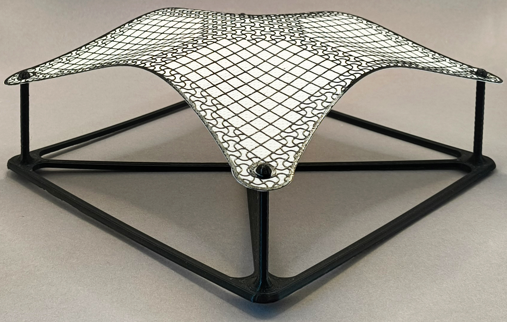
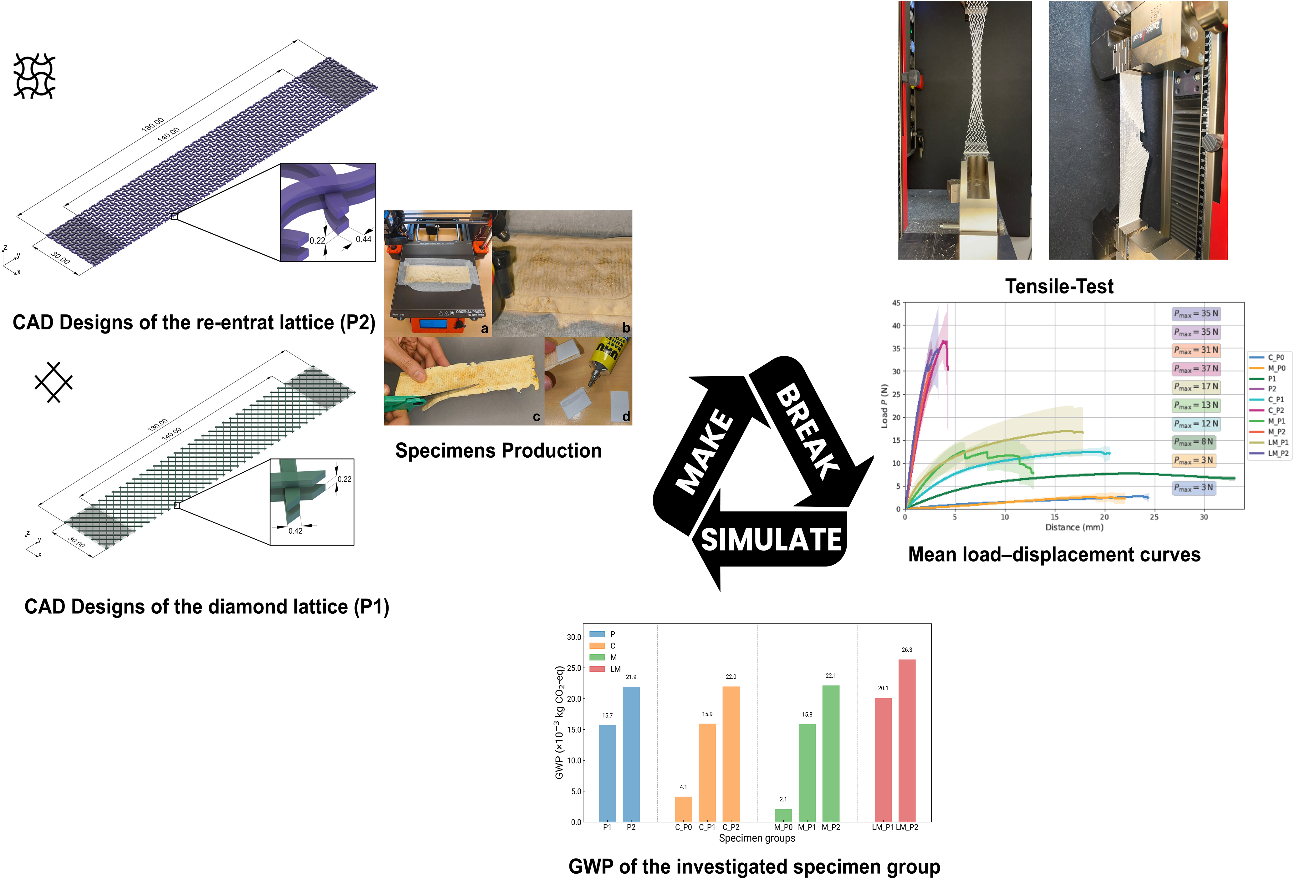
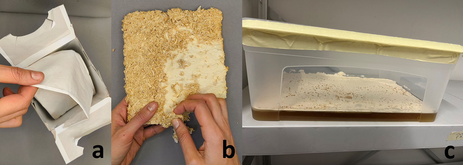
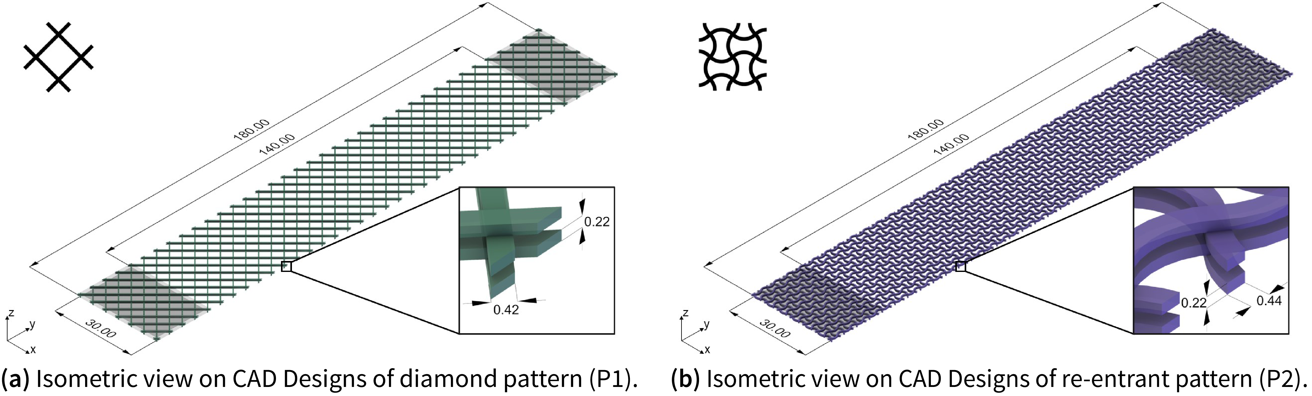
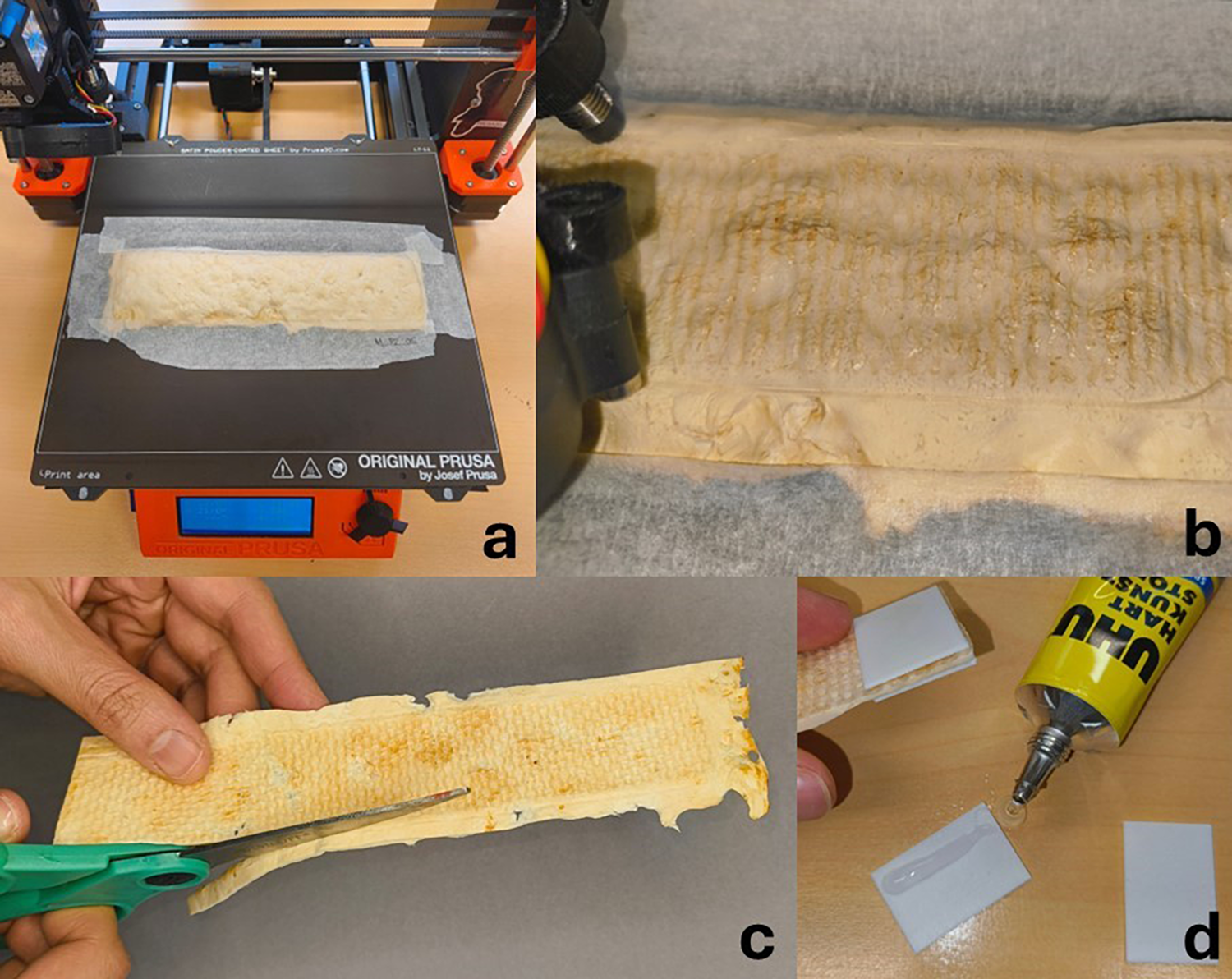
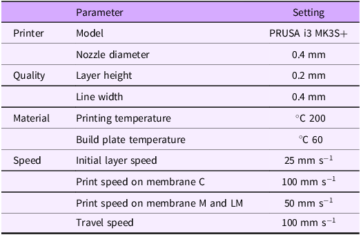
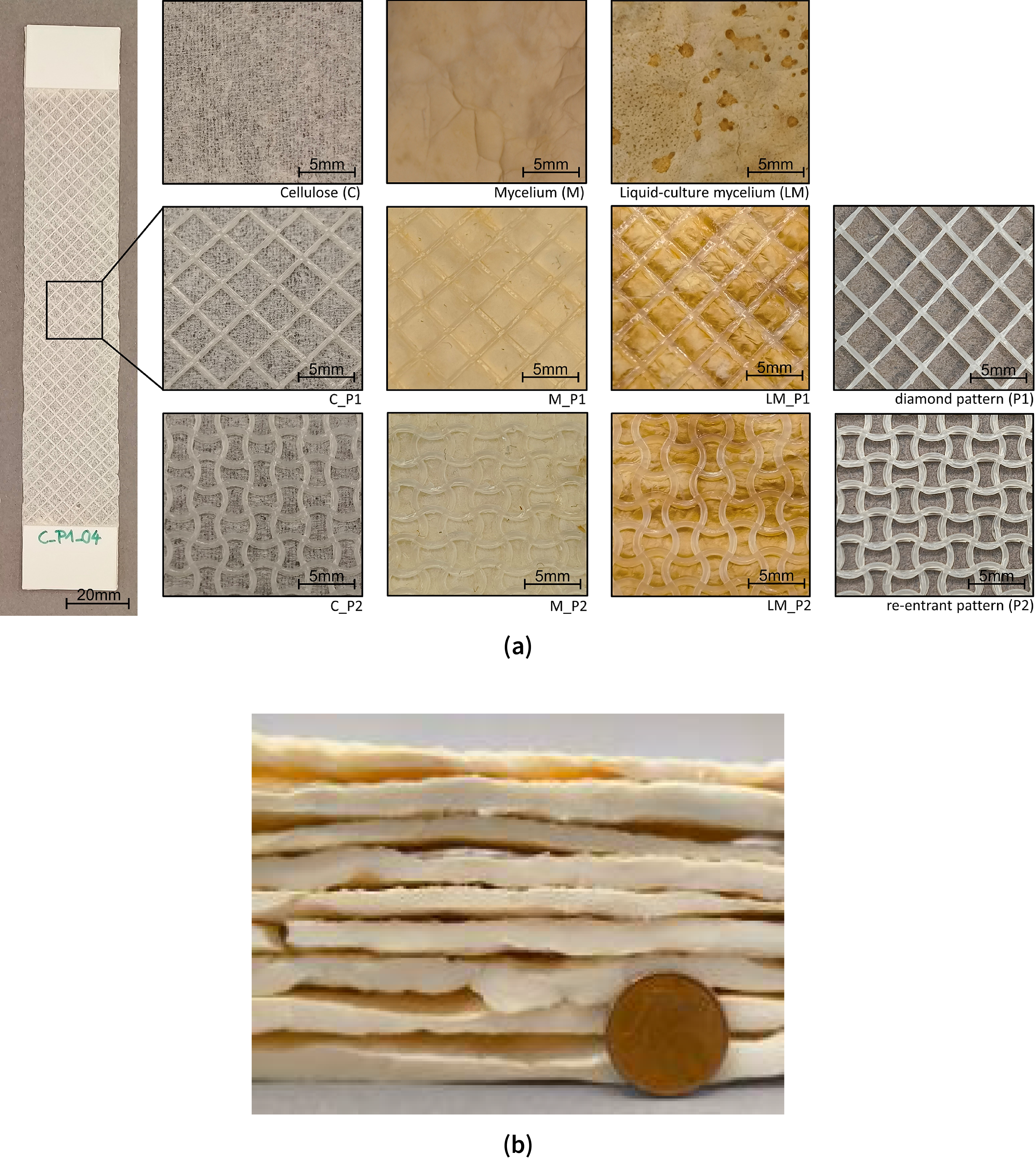
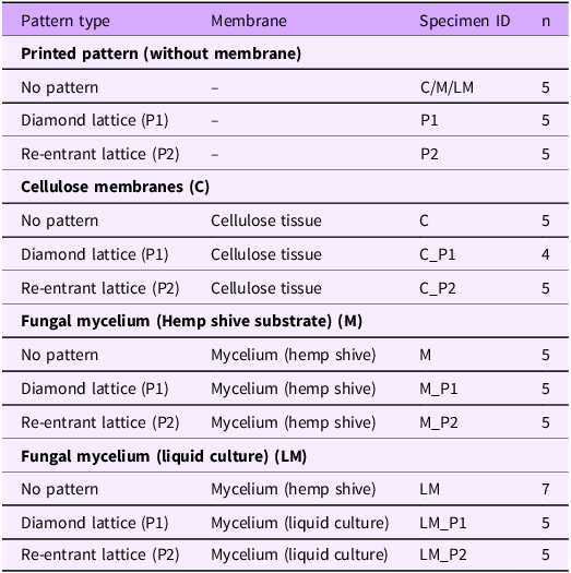
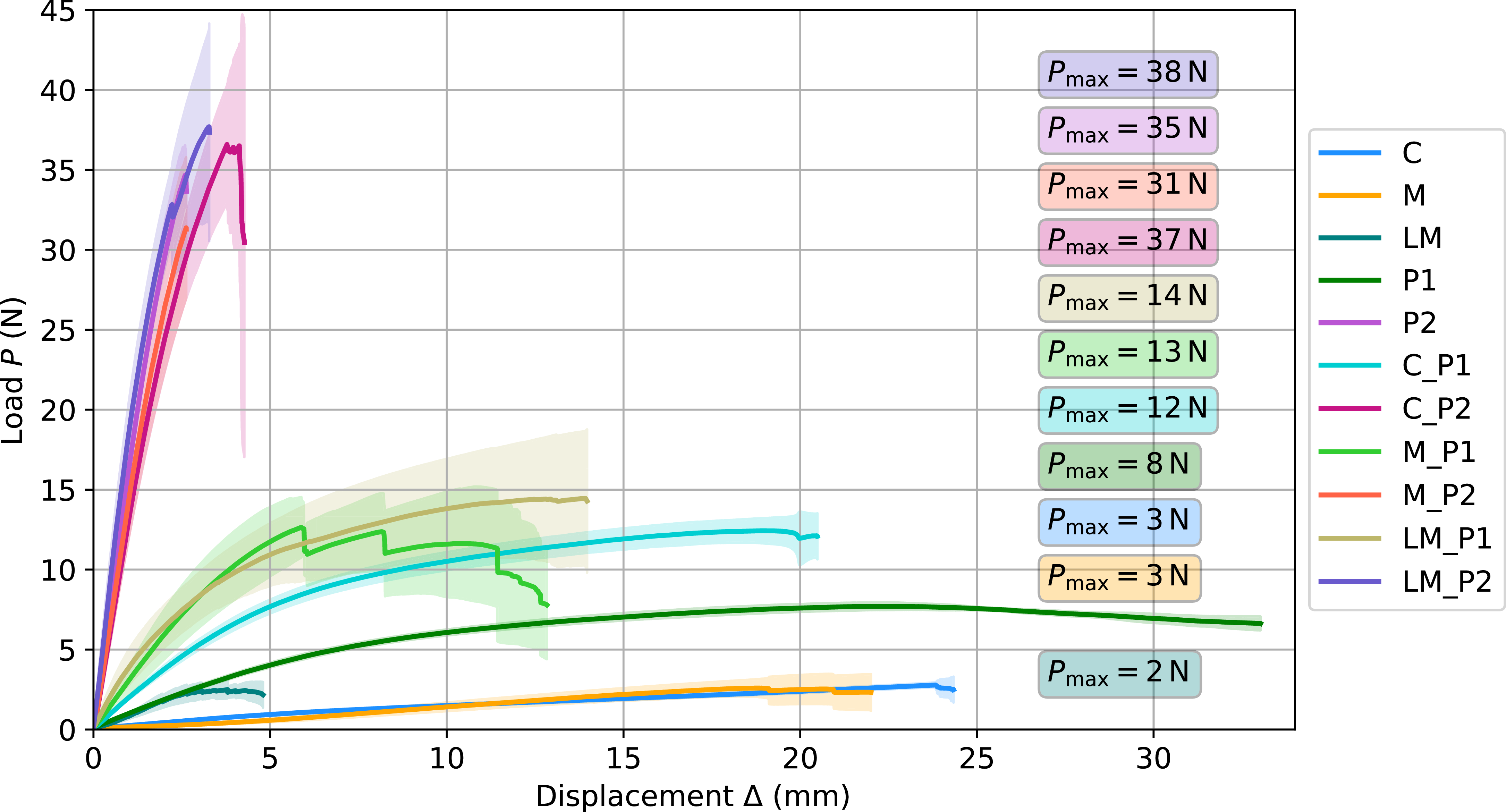
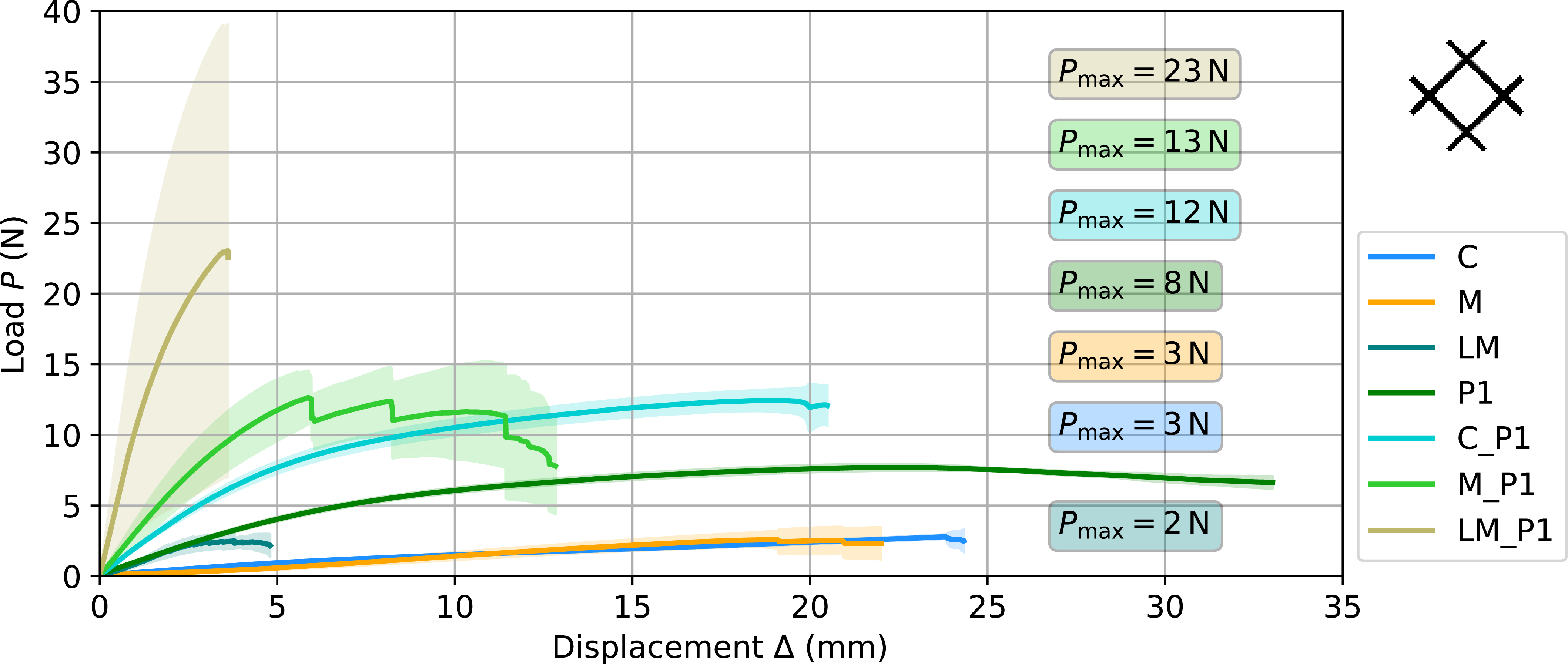
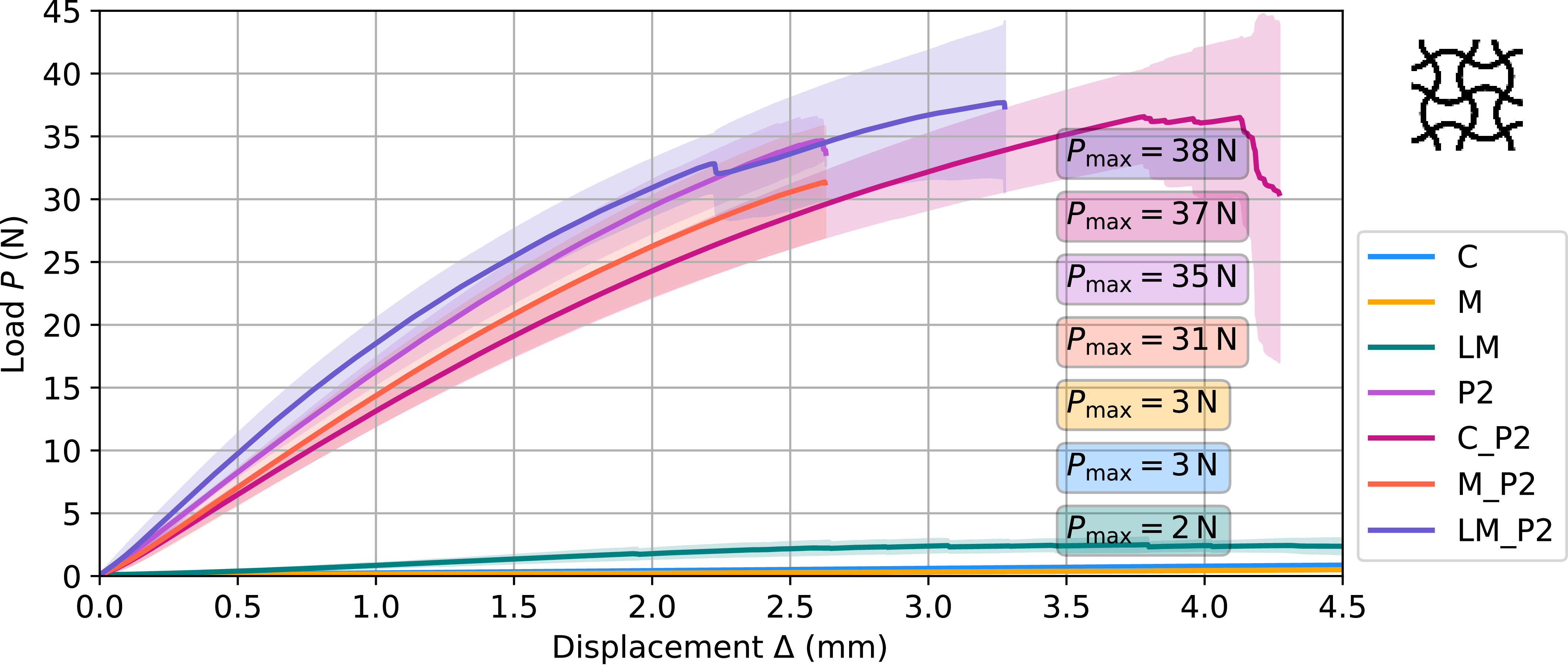
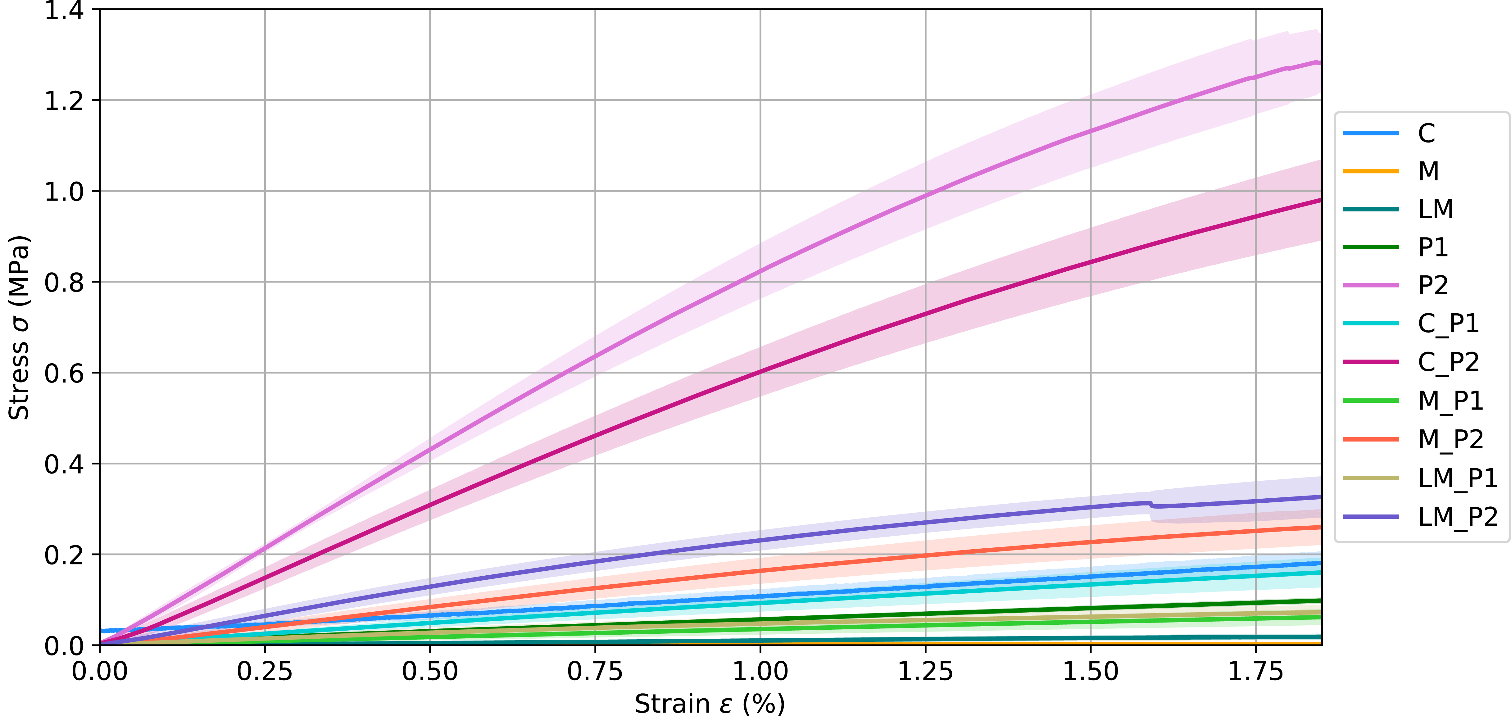
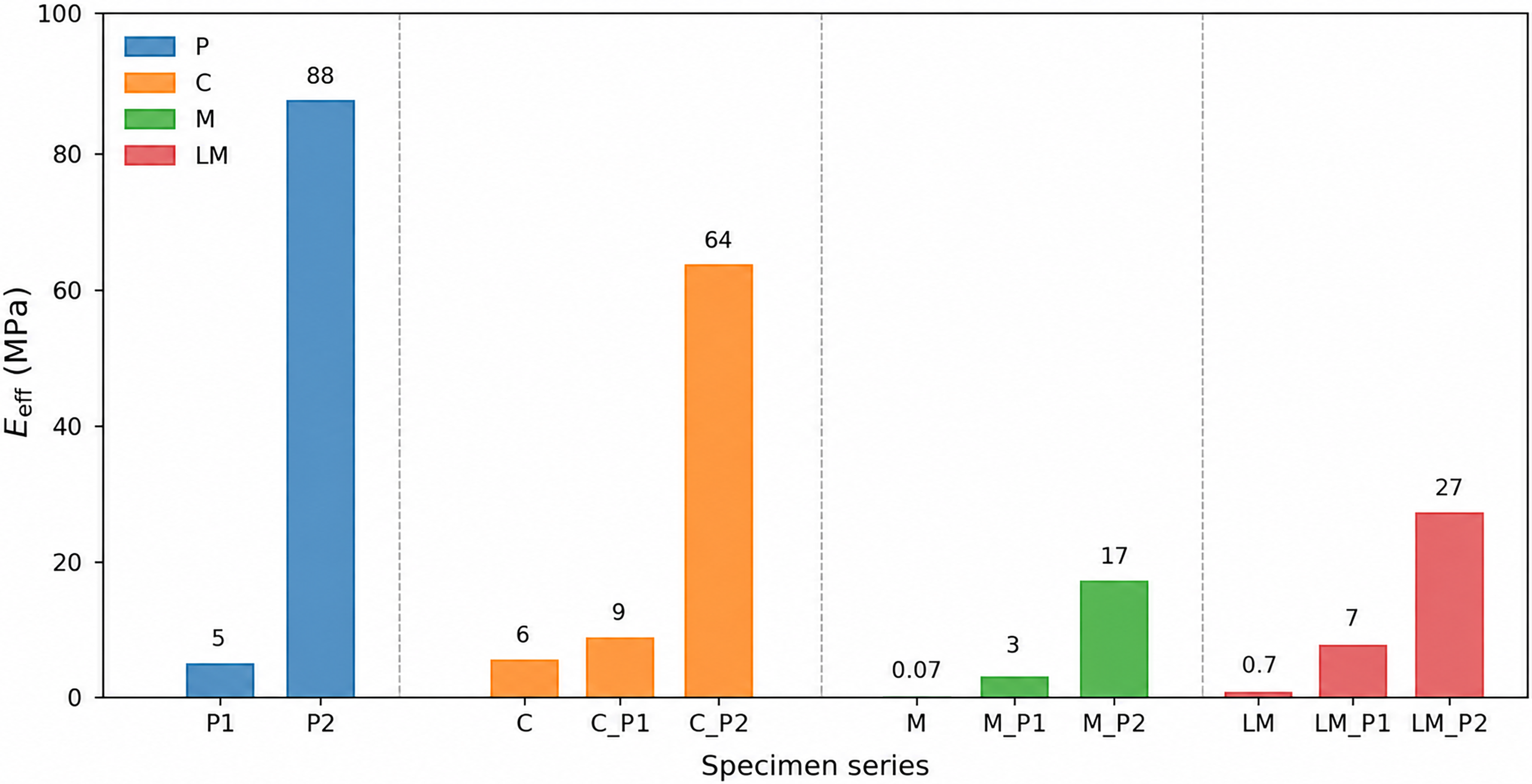
 Eeff
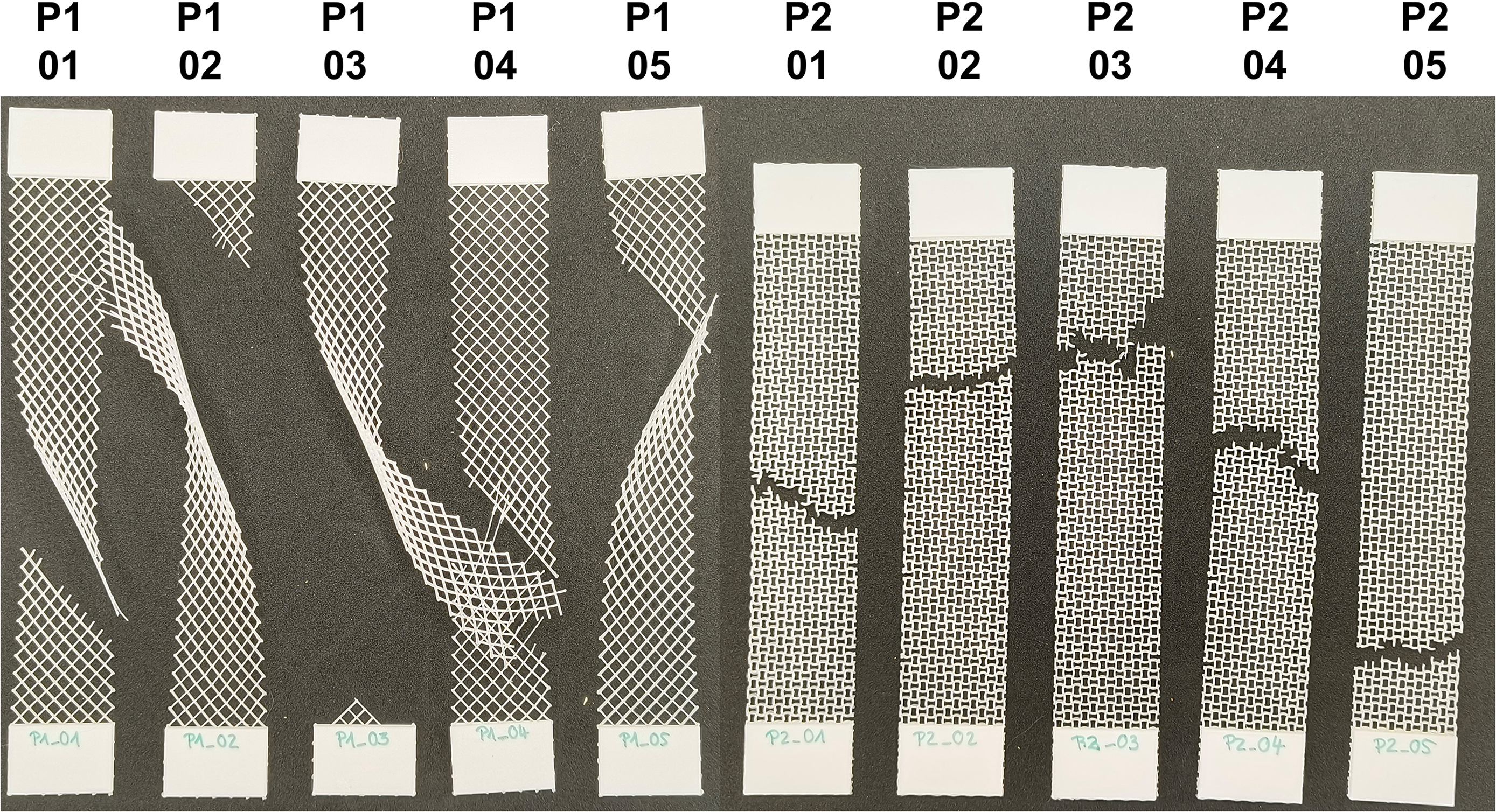
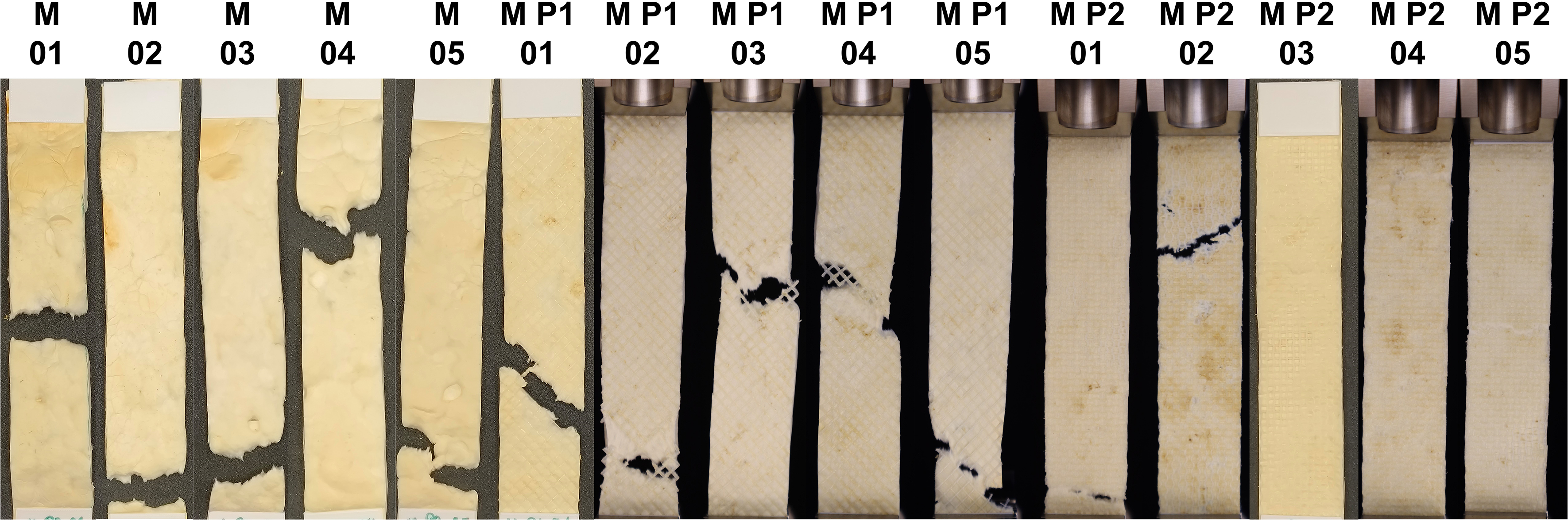
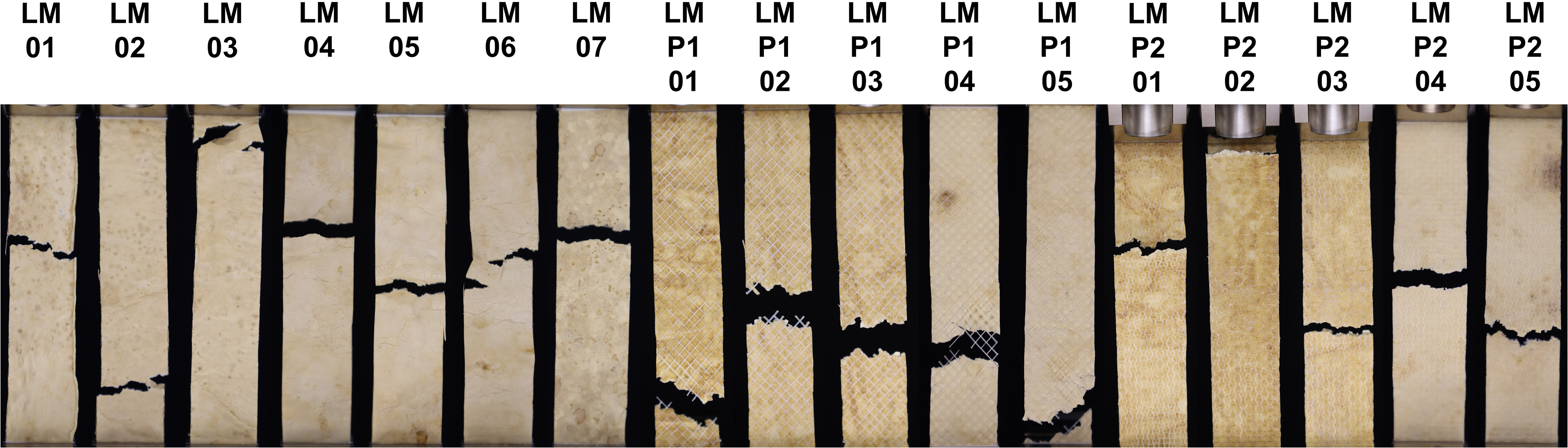
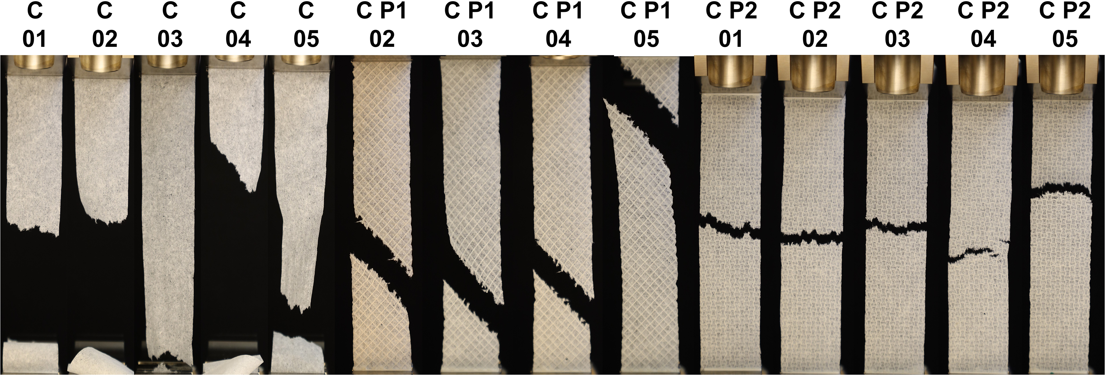
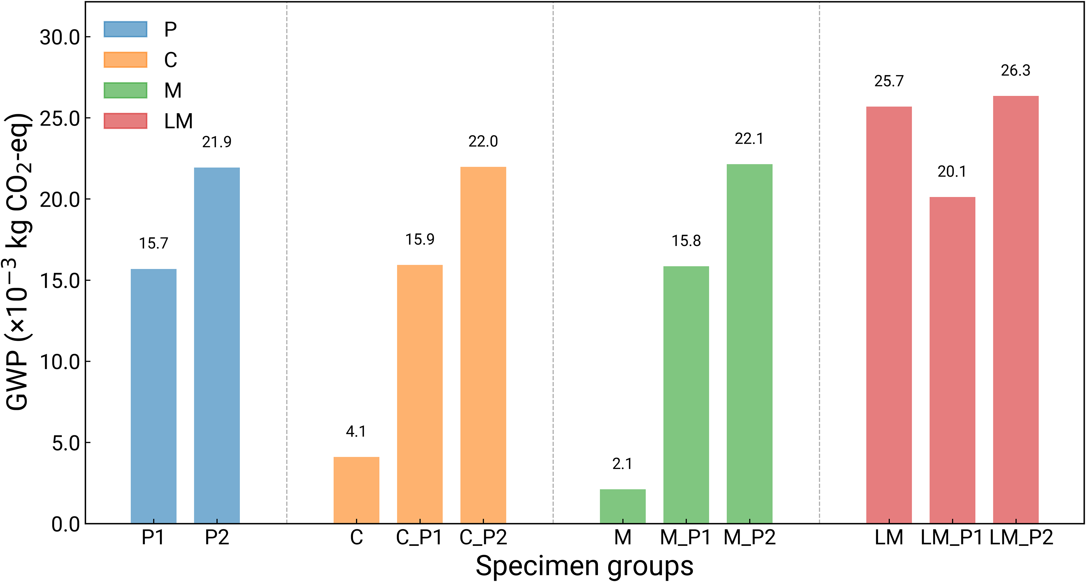
 10−3
 CO2
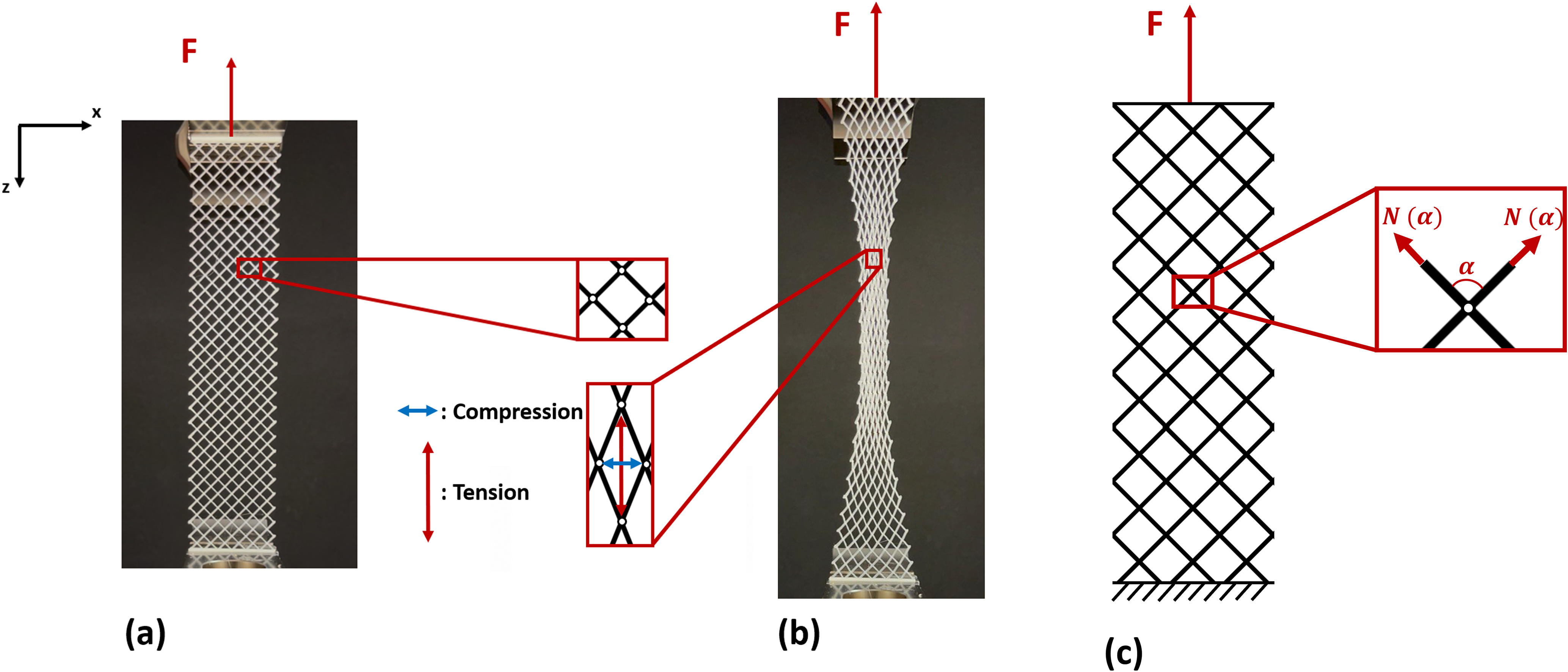
 N(α)
 α
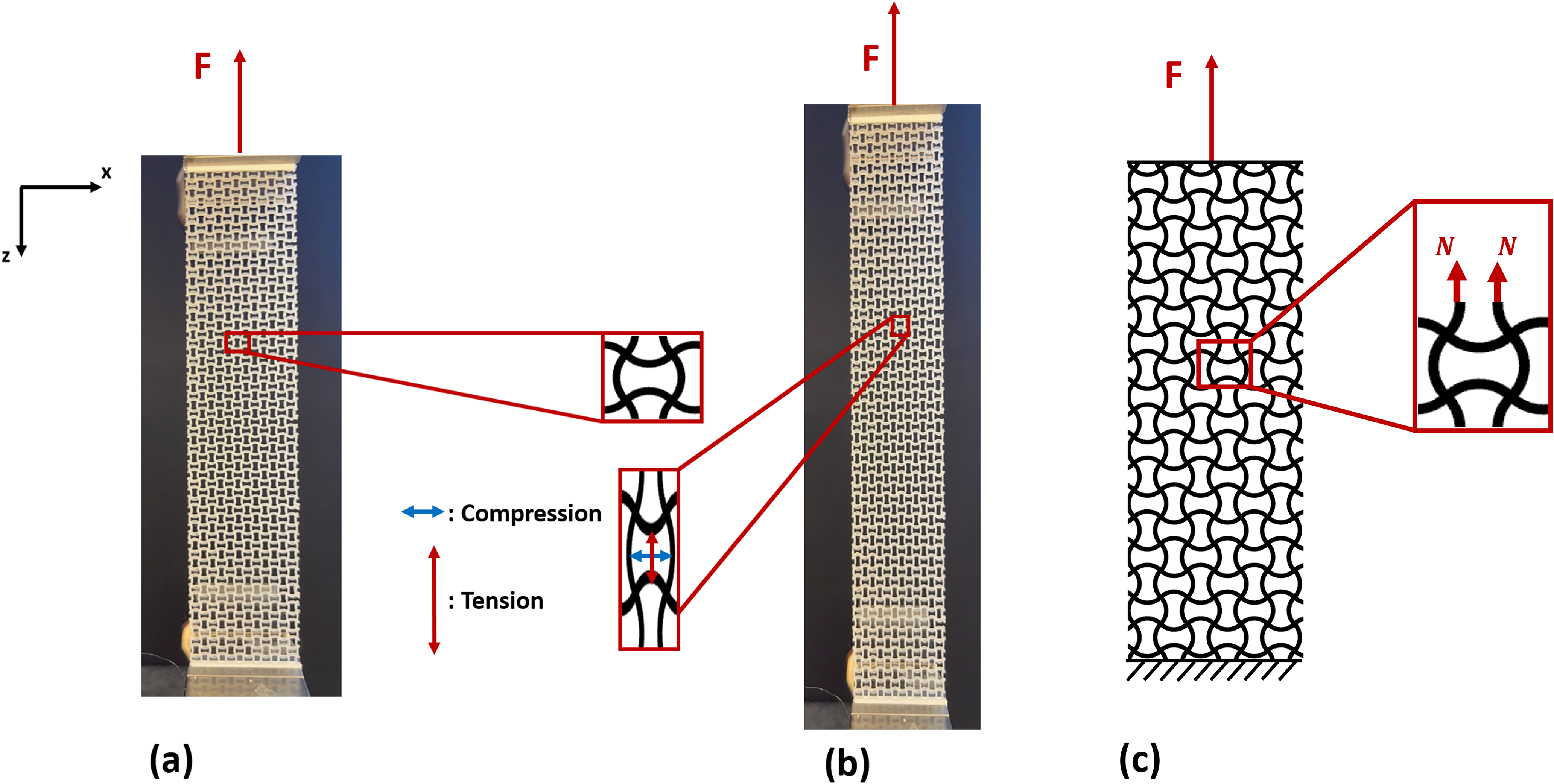
 N
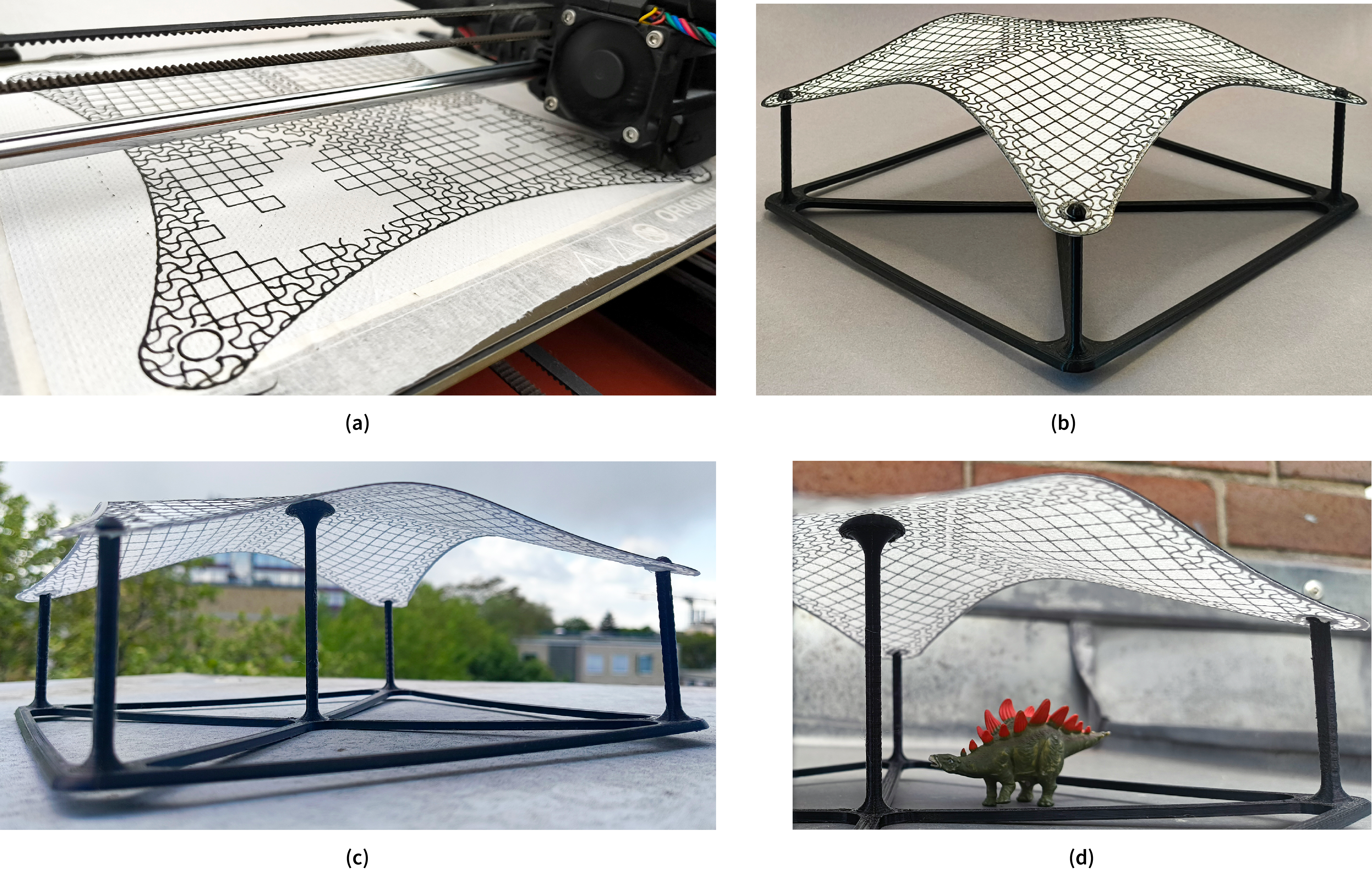
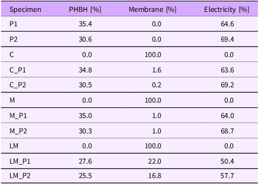
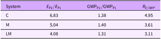
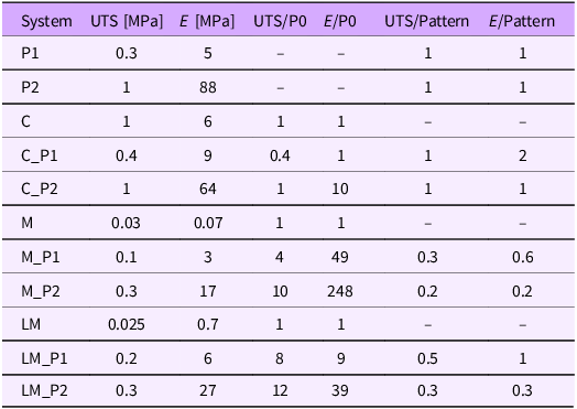


 Open access

