I. INTRODUCTION
The friction forces between a nanowire (NW) and a substrate are usually several magnitudes greater than the gravity force acting on the NW, due to the strong surface adhesive force.Reference Strus, Cano, Byron Pipes, Nguyen and Raman1–Reference Autumn, Liang, Hsieh, Zesch, Chan, Kenny, Fearing and Full4 In most of the NW/substrate based devices, the static friction force is the one that holds the NW in position and in shape,Reference Wang, Chen, Huang, Ma, Xu, He and Zou5,Reference Wang, He, Huang, Zou, Auchterlonie, Hou and Huang6 while the kinetic friction force will influence its movement.Reference Falvo, Taylor, Helser, Chi, Brooks, Washburn and Superfine7
Although friction has been brought into the field of physics for over centuries, the underlying mechanism of friction at nanoscale is not well understood yet as those laws that govern the friction at macroscale are not valid.Reference Mo, Turner and Szlufarska8–Reference Vanossi, Manini, Urbakh, Zapperi and Tosatti10 The nanoscale friction, e.g., that between a NW and a flat substrate, depends on the Van der Waals attraction at their interfaces,Reference Kim and Kim11 which is most relevant to the contact area.Reference Bordag, Ribayrol, Conache, Fröberg, Gray, Samuelson, Montelius and Pettersson12 As a consequence, surface texture, roughness and hydrophobic properties and the electric characteristics of contacted surfaces will significantly affect the magnitude of the friction force.Reference Polyakov, Vlassov, Dorogin, Kulis, Kink and Lohmus13–Reference DelRio, de Boer, Knapp, David Reedy, Clews and Dunn16
The previous studies were largely concerned with the determination of the static friction via bending manipulation. For instance, Bordag et al.Reference Bordag, Ribayrol, Conache, Fröberg, Gray, Samuelson, Montelius and Pettersson12 tried to bend a NW into a “half circle” of the smallest possible radius. The circumferential force of the NW was considered as the static friction force that was determined by the radius.Reference Bordag, Ribayrol, Conache, Fröberg, Gray, Samuelson, Montelius and Pettersson12,Reference Conache, Gray, Ribayrol, Fröberg, Samuelson, Pettersson and Montelius17,Reference Conache, Gray, Ribayrol, Fröberg, Samuelson, Montelius and Pettersson18 The method was later improved, so that a NW could be bent into arbitrary shapes and the static friction was estimated by calculating the elastic force generated in the bent NW that balances the static friction force.Reference Qin and Zhu14,Reference Stan, Krylyuk, Davydov and Cook19 This indicates that the friction force could be obtained using the high-order derivative of the NW profile. With the complete equilibrium equations, Dorogin et al.Reference Dorogin, Polyakov, Petruhins, Vlassov, Lõhmus, Kink and Romanov20,Reference Dorogin, Vlassov, Polyakov, Antsov, Lõhmus, Kink and Romanov21 obtained similar results and the additional term in their model was in fact proportional to the cube of the curvature. The improved model significantly increased the measuring accuracy,Reference Hou, Wang and Huang22 as the summation of external forces on the NW became zero.Reference Antsov, Dorogin, Vlassov, Polyakov, Vahtrus, Mougin, Lõhmus and Kink23
The kinetic friction between a NW and a substrate could be obtained by directly measuring the force reacted on the manipulator during the bending process.Reference Polyakov, Dorogin, Vlassov, Kink, Lohmus, Romanov and Lohmus24 However, the accuracy of the direct measurement was considerably hindered by the sensing resolution and other practical testing challenges. Alternatively, the kinetic friction forces could be measured by determining the load distribution of a NW by manipulating the NW end at fixed-free/fixed pin set-upsReference Zhu, Qin, Gu and Wang25,Reference Desai and Haque26 or using a mid-point bending test.Reference Dorogin, Polyakov, Petruhins, Vlassov, Lõhmus, Kink and Romanov20 Nevertheless, the complex nature of measuring instrumentation introduced many uncertainties, as well as the errors caused by the inappropriate assumptions, e.g., the neglect of the hysteresis of the NW's displacement and the shape change of the NW due to the frictional force redistribution after tip removal.Reference Stupkiewicz and Mróz27 Also, the midpoint location in a drag testReference Dorogin, Polyakov, Petruhins, Vlassov, Lõhmus, Kink and Romanov20 could affect the stability of manipulation. As a result, the reported values do not show good consistency, even for the same NW/substrate system.Reference Dorogin, Polyakov, Petruhins, Vlassov, Lõhmus, Kink and Romanov20,Reference Polyakov, Dorogin, Vlassov, Kink, Romanov and Lohmus28 It should also be noted that the currently available methods are unable to measure the static and kinetic friction in a single test. This might be one of the reasons for the significant discrepancy between the measured static and kinetic friction for the same NW/substrate interface.Reference Polyakov, Vlassov, Dorogin, Kulis, Kink and Lohmus13
This study aimed to develop a simple and reliable method that can measure the kinetic and static friction forces of a NW/substrate system in the same test. In this method, a NW was bent at one end. The kinetic friction force was determined by calculating the energy consumed during elastic recovery and the static friction force was obtained by calculating the restoring elastic force at the balanced position. Finite element analysis (FEA) was used to verify the experimental measurement.
II. TESTING METHOD
A. Testing process
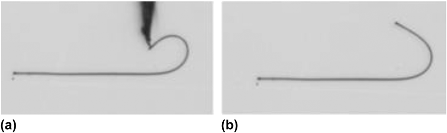
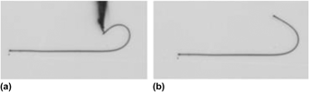
In this method, a NW is bent at one end into a hook shape by a manipulator, while the other end remains rest on the substrate, as shown in Fig. 1(a). Once the “hook” is formed and the manipulator tip is withdrawn, the NW bounces back slightly until the final equilibrium state is reached, where the static friction force is in balance with the elastic restoring force of the NW, as shown in Fig. 1(b). Depending on the extent of bending, the final equilibrium position will be changed. The images of the initial and final statuses of the bent wire are recorded by a digital camera.
Bending a NW on substrate, (a) the initial bending status and (b) the final bending status.

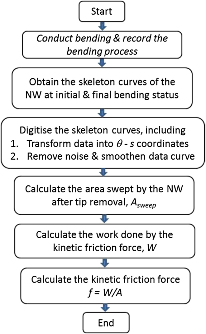
Figure 2 shows the procedure for determining the kinetic friction force. The curves of the NW were skeletonised at its initial and final statuses. The skeleton curves were then digitised after being converted into a natural coordinate system and signal processing. After that, the area swept by the NW and the work done by the friction force could be determined, hence the kinetic friction force. Detailed description of each module will be given in the following sections.
The procedure to determine the kinetic friction force.

B. Skeletonisation and digitisation of NW profiles
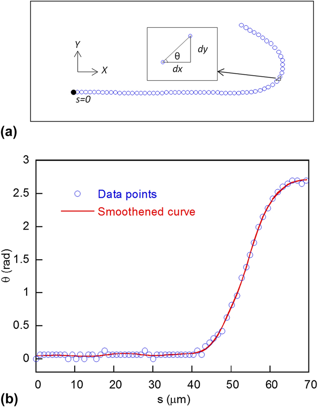
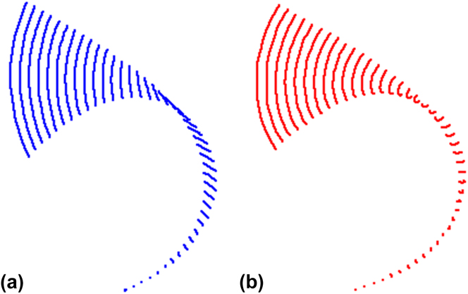
The skeletonised curve of a bent NW at the initial and final stages can be captured from the optical images and then converted into the digitised curve using Matlab. Figure 3(a) shows a typical digitised curve of the bent NW located in a Cartesian coordinate system (x, y). For the convenience of analysis, the curve was replotted in a coordinate system (θ, s), as shown in Fig. 3(b). Here, s is the curve length from a given point to the origin (i.e., the rest end point of the NW in our case) and θ is the angle between ds and dx. It is apparent that the digitised data points (in blue color) are slightly scattered at some locations, as the relatively low resolution of optical imaging introduced noise into the signal during skeletonization. The noise must be removed as it can result in significant error in its local derivative that is required in our further calculation of the elastic energy. To remove the noise, fast Fourier transform was performed on the data to obtain its frequency domain signal and a low pass window function was then used to smoothen the data. The curve after filtering (represented by the red solid line) is also shown in Fig. 3(b).
(a) A skeletonised curve captured from the optical image of a typical NW plotted in a Cartesian coordinate system, and (b) the curve converted into the coordinate system (θ, s).

C. Swept “area”
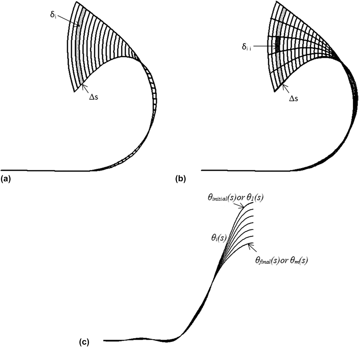
The area that the NW swept from the initial status (right after the tip withdrawal) to the final status (or equilibrium status) needs to be determined for calculating the kinetic friction force. Figure 4(a) schematically shows the swept area, which can be divided into n segments along the NW. Each segment has a width of ∆s j (= the bent length/n) and a path length of δj (j is the index of each segment). Therefore, the swept area can be calculated as,
 $${A_{{\rm{swept}}}} = \mathop {\lim }\limits_{n \to \infty } \left( {\mathop\sum\limits_{j = 1}^n {{\delta _j} \cdot \Delta {s_j}} } \right)\quad .$$
(a) The swept area was divided into n elements, (b) the δj-th was further divided into (m + 1) elements by m in-between curvatures, (c) the in-between curvatures obtained from the natural coordinate system.

In Eq. (1), δj cannot be directly obtained from the measurement, unless the position of the NW during its recovery process can be recorded (which often makes manipulation difficult as the process is usually in microseconds). In this work, the swept area was further divided by m in-between NW curves, as shown in Fig. 4(b), so the area now consists of n × (m + 1) small elements. Thus, δj can be expressed as
 $${\delta _j} = \mathop {\lim }\limits_{m \to \infty } \mathop\sum\limits_{i = 1}^{m + 1} {{\delta _{j,i}}} \quad .$$
Substituting Eq. (2)into Eq. (1), we obtain
 $${A_{{\rm{swept}}}} = \mathop {\lim }\limits_{n \to \infty } \left( {\mathop\sum\limits_{j = 1}^n {\mathop {\lim }\limits_{m \to \infty } } \mathop\sum\limits_{i = 1}^{m + 1} {{\delta _{j,i}} \cdot \Delta {s_j}} } \right)\quad ,$$
where δj,i is the path length of an arbitrary small element. Practically, from the Cartesian coordinate system it is difficult to generate the in-between NW curves, but it is much more convenient to produce in the coordinate system (θ, s) by assuming that the segment Δs j has a regular angular velocity, i.e., (dθj/dt), is proportional to [(θj)final − (θj)initial]. Therefore, in the (θ, s) coordinates, the m in-between curves can be obtained by equally dividing the total swept angle (θj)swept by (m + 1) at any point, s j, as shown in Fig. 4(c). For an arbitrary element [see the shaded area in Fig. 4(b)], its node coordinate values, (θi, s j), (θi+1, s j), (θi+1, s j), and (θi+1, s j+1), can be found from the curves in Fig. 4(c), and those coordinates are converted into the corresponding Cartesian coordinates again to achieve the area. The swept area is thus calculated using Eq. (3). A swept is converging with the increase of the element numbers (i.e., n and m).
D. Kinetic friction work and force
Based on the Euler beam theory, the elastic energy, U, of a bent NW can be determined byReference Frisch-Fay29
 $$U = \int\limits_0^L {{{EI} \over 2}{k^2}{\rm{d}}s} \quad ,$$
where L is the length of the NW, E is the elastic modulus, I is the second moment of area or the area moment of inertia, and k is the curvature along the NW profile.
The difference between the restoring elastic energy at the initial state, U initial, and that of the final state, U final, is equal to the work, W f, done on the NW by the kinetic friction force, i.e.,
 $${W_{\rm{f}}} = {U_{{\rm{final}}}} - {U_{{\rm{initial}}}}\quad .$$
On the other hand, the frictional work of the whole NW can also be calculated by
 $$W_{\rm{f}} = \mathop {\lim }\limits_{n \to \infty } \left( {\mathop\sum\limits_{j = 1}^n { - f^k \cdot \Delta s \cdot \delta _j } } \right) = - f^k A_{{\rm{swept}}} \quad ,$$
where the negative sign indicates that the displacement always has an opposite direction to the kinetic friction force.
Therefore, the kinetic friction force can be derived from,
 $${f^k} = {{\left( {{U_{{\rm{final}}}} - {U_{{\rm{initial}}}}} \right)} \mathord{\left/ {\vphantom {{\left( {{U_{{\rm{final}}}} - {U_{{\rm{initial}}}}} \right)} {{A_{{\rm{swept}}}}\quad .}}} \right. \kern-\nulldelimiterspace} {{A_{{\rm{swept}}}}\quad .}}$$
E. Static friction force
Assuming that the tangential component of the static friction force could be negligible, the normal component could be derived from the force equilibrium equations of a bent NW attached to a substrate,Reference Dorogin, Polyakov, Petruhins, Vlassov, Lõhmus, Kink and Romanov20 and expressed as
 $$f_n^{{\rm{st}}} = EI\left[ {{{{{\rm{d}}^3}\theta } \over {{\rm{d}}{s^3}}} + {1 \over 2}{{\left( {{{{{\rm{d}}^2}\theta } \over {{\rm{d}}{s^2}}}} \right)}^3}} \right]\quad .$$
The static friction force generally reaches its maximum near the bending apex. We will use Eq. (8) to calculate the maximum value of static friction force along the NW, and the value will be compared to the kinetic friction force from Eq. (7).
III. FINITE ELEMENT MODELING (FEM) VERIFICATION
A. FEM model
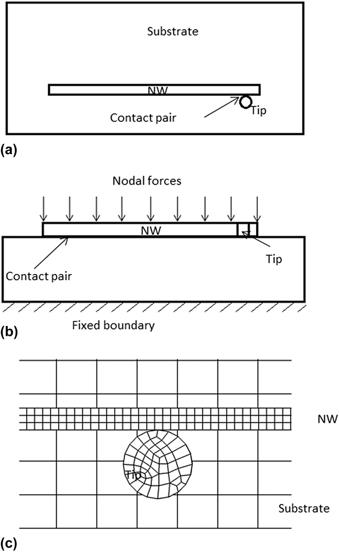
FEM was first used to test the method. A typical NW was selected, which has a height of 334 nm, a width of 254 nm, and a length of 70 μm, the same dimensions as the NW shown in Fig. 1. The top and cross-sectional views of the geometric model are shown in Figs. 5(a) and 5(b). The substrate was constrained, but the NW was free in all degrees of freedom. Contact/target pairs were generated at the area where the NW/substrate and NW/tip is likely in contact. Normal nodal forces were applied on all the nodes on the top surface of the NW to simulate the adhesion between the NW and substrate. Friction was assumed to be 10% of the adhesion force, i.e., equivalent to a friction coefficient of 0.1 set for the contact elements.Reference Bhushan and Sundararajan30 The direction of the frictional force at a specific node was not restricted. During computation, the force direction would vary according to the velocity direction of the specific mass point. The model was meshed and operated using ANSYS-LS DYNA software. The NW, tip, and substrate were meshed using solid164 element, as shown in Fig. 5(c). The NW had 650, 4, and 3 elements along its length, height, and width directions, respectively. During computation, the displacement, velocity, and acceleration of the NW were calculated (by explicit method) using a time step of 0.01 ms and the total time of 1 ms for the recovery process. The elastic modulus of the alumina NW was taken to be 310 GPa, measured by the thermal vibration methodReference Wang, He, Huang, Zou, Auchterlonie, Hou and Huang6 and its nominal Poisson's ratio of 0.2 and density of 3.96 g/cm3 were used in the model.Reference Lide31 The Si substrate has an elastic modulus of 112 GPa, Poisson's ratio of 0.3, and density of 2.3 g/cm3.Reference Lide31 The W manipulator tip had an elastic modulus of 400 GPa, Poisson's ratio of 0.3, and density of 19.3 g/cm3.Reference Lide31
The geometric model: (a) top view and (b) front view. (c) Mesh of the model, viewing from the top.

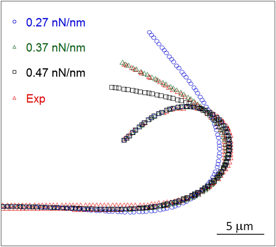
During modeling, a displacement was enforced on the manipulator tip that simulated the bending of the NW into the initial bending status, as shown in Fig. 1(a). The tip was then withdrawn, and the NW bounced back into the final status. Prior to simulation, an initial friction force was input in the form of normal force multiplied by friction coefficient. During simulation, the normal force was automatically adjusted using an iteration method to achieve the best fit to the target status, i.e., experimental measurement [see Fig. 1(b)]. Figure 6 shows the simulated final bending status obtained from different friction forces. Apparently, the final shape of the NW was dependent on the input friction force, and the value of 0.37 nN/nm gave the best fit to the experimental measurement.
The simulated final bending statuses at different friction forces, in comparison to the experimental.

B. Verification of the analytical model
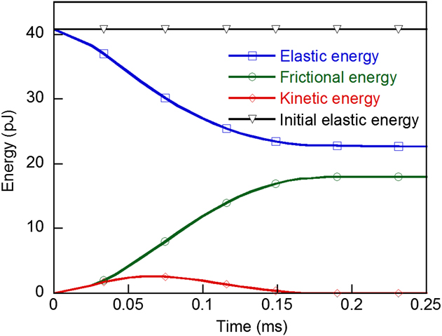
Figure 7 shows the simulated energy transfer during the recovery process. When the NW begins to bounce back, part of the elastic energy is transferred into kinetic energy and some of the elastic energy is consumed by kinetic friction. The sum of the elastic, kinetic, and friction energies remains constant that is equal to the elastic energy of the NW at the initial bending status. The conservation of energy transfer validated Eq. (4).
Energy conversion during the restoring process obtained from FEM simulation.

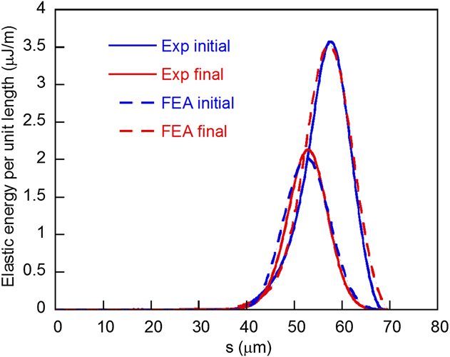
Figure 8 shows the comparison of the elastic energy distributions obtained from Eq. (5) and the FEA result. The energy consumed by the friction force was 18.8 pJ from the analytical calculation and 17.9 pJ from the simulation (calculated based on Von-Mises stress and strain). The simulation result is in good agreement with the analytic calculation. Figure 9 shows the NW's displacement trajectories during the recovery process obtained from the analytical calculation and the FEM simulation, which do not show significant difference. The value of A swept calculated from Eq. (3) was 47 μm2 while the simulated value was 49 μm2. Using the area and energy values in Figs. 8 and 9, the kinetic friction force calculated from analytical solution was 0.4 nN/nm, agreeing well with the simulated value of 0.37 nN/nm.
Comparison of elastic energies at the initial and final statuses obtained from FEM and analytical calculation using Eq. (8).

The NW's displacement trajectories during the restoring process obtained from (a) the analytical calculation and (b) FEA simulation.

IV. EXPERIMENT
A. Testing condition
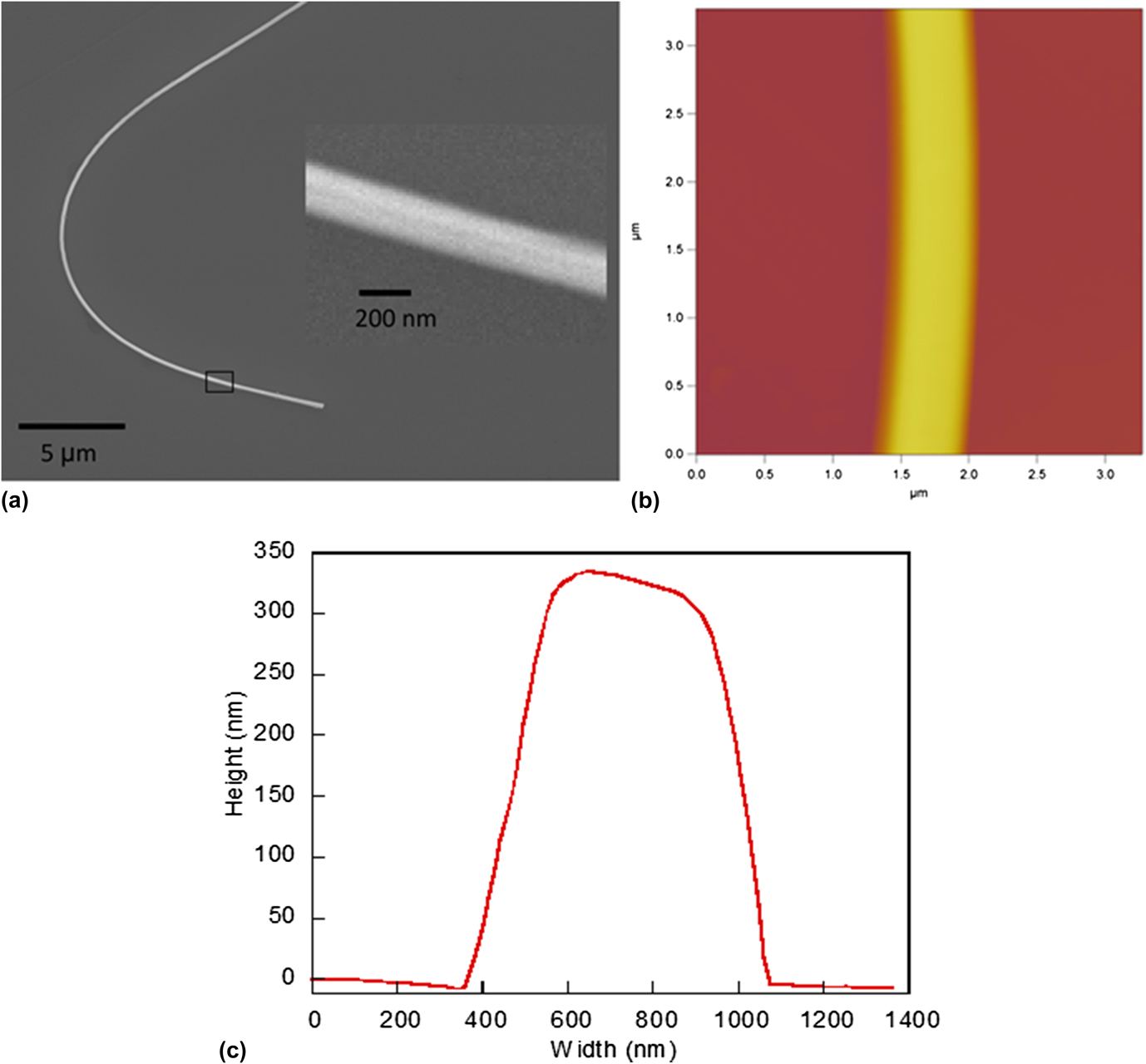
Eight Al2O3 NWs were used for testing, which were fabricated using high-temperature chemical vapor depositionReference Wang, He, Huang, Zou, Auchterlonie, Hou and Huang6 and had different values in length and width, as shown in Table I. The specimens were dispersed in alcohol and then dropped onto a Si substrate for drying before being transferred onto the target Si substrate with roughness of 0.8 nm for friction testing. The uniformity and geometry of the NWs were examined and measured using atomic force microscopy (AFM, Asylum Research MFP-3D) and scanning electron microscopy (SEM; JEOL JSM-7001F, JEOL Ltd., Tokyo, Japan, operated at 15 kV). Figure 10 shows a typical NW that had a uniform cross-section along the length [see Figs. 10(a) and 10(b)] and the cross-section had a height of 334 nm and a width of 254 nm, as shown in Fig. 10(c). The friction tests were performed under the optical microscope (objective lens: Mitutoyo M Plan APO 50x and HR 100x) at the temperature of ∼25 °C and relative humidity of ∼35%.
Geometric dimensions and friction forces of the NWs.

(a) The SEM image of an Al2O3 NW on a Si substrate; (b) and (c) the AFM cross-sectional profile of the NW.

B. Results
Following the measuring procedure in Fig. 2, the kinetic friction force was computed using Eq. (7). For comparison, the static friction forces were calculated using Eq. (8). The interfacial shear stress, σkin and σsta, are defined by the kinetic and static friction force per unit of contact area at the NW/substrate interfaces. It can be seen from Table I that the σkin values vary slightly from 1.16 to 3.4 MPa for the Al2O3 NW samples with different widths and heights. The σsta values are in the range from 0.68 to 2.7 MPa, which are reasonably consistent with σkin. Our measured kinetic forces also agree well with those obtained from the AFM measurements that are in the range from 1 to 2 MPa for most of the NWs or nanoparticles on flat substrates.Reference Falvo, Taylor, Helser, Chi, Brooks, Washburn and Superfine7,Reference Conache, Gray, Ribayrol, Fröberg, Samuelson, Pettersson and Montelius17,Reference Meyer, Overney, Brodbeck, Howald, Lüthi, Frommer and Güntherodt32–Reference Kim, Kang and Kim34 From Table I, it can also be seen that the interface shear stress exhibited no apparent relationship to the width or length of the NWs.
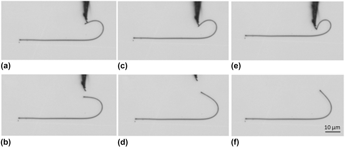
We also tested the effects of initial bending status on the calculated results. As shown in Fig. 11, a NW was pushed to different bending profiles. After the tip withdrawal, the NW bounced back to different final statuses. Obviously, the more bent the initial state, the larger the “swept area”. However, the calculated kinetic friction had no dependence on the initial status, as shown in Table II. At the same time, the obtained maximum value of static friction (near the apex) for these three cases did not vary significantly, although the static friction distribution was sensitive to the bending shape of the NW.
The same NW was manipulated to (a, c, e) three different initial statuses and (b, d, f) three final statuses.

The friction forces of the same NW under three different bending statuses.

The major error source in this approach was from the calculation of A swept, because the actual trajectories of all the mass points are based on the assumption of the regular angular velocity. This might introduce an error of up to 10% into the calculation. The energy calculation using Eq. (5) would also lead to an uncertainty of about 5%, most probably due to the skeletonisation inaccuracy and digital signal distortion. It should be noted that image resolution could affect the measuring accuracy, but such an effect is small in this work because the area “swept” by the NW was sufficiently large (tens of square micrometer). This enabled the measurement to be performed even using a lower magnification optical microscope.
V. CONCLUSIONS
This study demonstrated that the developed method could experimentally determine both kinetic and static friction forces of Al2O3 NWs on Si substrate. The method appeared concise and reliable as the elastic recovery movement of the NW was repeatable and not affected by the initial bending status. The FEM simulation demonstrated that the developed energy model was accurate and validated the methodology that is based on analytical calculation. Experimental testing of Al2O3 NWs on silicon substrate demonstrated that the kinetic friction forces on a unit area varied from 1.16 to 3.40 MPa, irrelevant to the width or length of NWs. Those values were consistent with the static friction being measured that ranged from 0.68 to 2.70 MPa.
ACKNOWLEDGMENTS
The work was financially sponsored by the Australia Research Council (ARC) under Discovery Project (DP130101828) and Future Fellowship (FT110100557) schemes. HTX was supported by The University of Queensland Research Scholarship (UQRS). The authors would also like to acknowledge the Australia National Fabrication Facility (ANFF) for AFM microscopy and Mr. Jiawen Su for his help in signal processing.