I. INTRODUCTION
Particle reinforced aluminum matrix composites (AMCs) are one of the effective alternatives in aerospace and automobile industries due to their excellent mechanical properties and their advantage of being machinable using conventional processing methods. Reference Miracle1 Considering the characteristics of particle reinforced AMCs, the reinforcing materials have played a significant role in determining their whole performances. Therefore, conventional ceramic particles, such as silicon carbide particle (SiCp), Reference Umasankar, Anthony Xavior and Karthikeyan2,Reference Wu, Kim, Anderson and Lograsso3 alumina (Al2O3), Reference Rahimian, Ehsani, Parvin and Baharvandi4 and boron carbide (B4C), Reference Habibi, Hamouda and Gupta5,Reference Rezayat, Bahremand, Parsa, Mirzadeh and Cabrera6 have been widely applied due to their excellent mechanical properties in the past decades. Although these ceramic particle reinforced AMCs already exhibited excellent enhancing effect on their tensile strength, the simultaneously improved tensile strength, toughness, and other properties of AMCs were difficult. To solve this problem, hybrid reinforcements composed of two or more reinforcements have attracted a great interest to some researchers. Oh and Han Reference Oh and Han7 fabricated 6061Al matrix composites reinforced with Al2O3 short fibers and particles, respectively. They indicated that, in the Al2O3 short fiber/particle hybrid AMCs, the crack growth path was shifted due to the existence of short fiber and the toughness was enhanced. Iqbal et al. Reference Iqbal, Arai and Araki8 studied the initiation, interaction, and coalescence of fatigue micro-cracks in casting hybrid AMC reinforced with SiCp and Al2O3 whiskers. They found the similar result that both strength and toughness were improved by addition of hybrid reinforcements. On the other hand, many researchers Reference Ravindran, Manisekar, Vinoth Kumar and Rathika9–Reference Alizadeh, Abdollahi and Biukani12 have revealed that the addition of both hard particles (SiCp) and solid graphite lubricant particles improves the tribological properties of AMCs. The advantage of SiCp/graphite/Al composite is that they are self-lubricating materials, and yet their strength is improved by the presence of micro-sized ceramic SiCp. Learning from the literature above, most of them are limited in the investigation of fracture mechanism and wear properties about hybrid reinforced AMCs. However, the studies of the synergetic strengthening effect of hybrid reinforcements were rarely reported.
Recently, novel carbonaceous nanomaterials, such as carbon nanotube (CNT) and graphene, with unique fascinating properties were discovered in succession and quickly attracted great interest as reinforcements in AMCs. Reference Choi, Kwon, Lee and Bae13–Reference Li, Wang, Fan, Pan, Chen and Zhang16 However, owing to the strong van der Waal’s force among them and large size discrepancy compared to metal matrix, it is quite difficult to fulfill their potential enhancing effect in AMCs. Many attempts, such as high energy ball milling, flake powder metallurgy, molecular level mixing, and nanoscale dispersion, have been made to achieve uniform dispersion and fully exploit the enhancing efficiency of CNT. But all of these techniques have evinced a varying degree of success with some limitations. During high energy ball milling and flake powder metallurgy, Reference Wang, Choi, Myoung and Lee17–Reference Jiang, Li, Fan, Cao and Zhang19 CNT receives impact energy from the rolling balls and the structure and integrity of CNT may be damaged even destroyed. Molecular level mixing Reference Cha, Kim, Arshad, Mo and Hong20 requires the functionalization of CNT which introduces defects and deteriorates its properties. In the process of nanoscale dispersion, Reference Nam, Cha, Lim, Park, Han and Hong21 the addition of natural rubber as a mixing medium may introduce undesirable impurities and give low density to the composite. Therefore, the traditional powder metallurgy was selected as the main fabricating technique in our work.
In this paper, we have developed a novel and simple approach to uniformly disperse CNT in Al matrix, in which CNT was firstly in situ synthesized on the surface of micro-sized SiCp to form the SiCp(CNT) hybrid reinforcement by chemical vapor deposition (CVD). 17 wt% SiCp(CNT)/Al composites were fabricated and investigated to find out the effect of varying CNT content in SiCp(CNT) hybrid reinforcement on the mechanical performance of SiCp(CNT)/Al composites. Three types of SiCp(CNT) hybrid reinforcement with CNT contents of 3, 6, and 9 wt% were synthesized by controlling the CNT growth time in CVD process. SiCp(CNT)/Al composites reinforced with three different SiCp(CNT) hybrid reinforcements were also fabricated by conventional powder metallurgy. The SiCp(CNT)/Al composites reinforced by SiCp(CNT) hybrid reinforcement with CNT content of 3 wt% showed simultaneously improvements in both tensile strength and ductility, and those reinforced by SiCp(CNT) hybrid reinforcement with CNT content of 6 wt% gave the most significantly strengthening efficiency in mechanical properties of composites.
II. EXPERIMENTAL PROCEDURES
A. Raw materials
Atomized pure Al powders (99.9 wt% in purity) with particle size of ∼10 μm and commercial SiCp with particle size of ∼7 μm were selected as the raw materials for producing the SiCp(CNT)/Al composites in this study.
B. Processing of SiCp(CNT)/Al composites
1. Preparation of SiCp(NiO) catalyst precursor
The required amounts of Ni(NO3)2·6H2O (8.6 g) and SiCp (33 g) were mixed in 500 mL deionized water to yield a weight ratio of Ni/SiCp = 5:95. NaOH (0.5 mol/L, 120 mL) was added to the mixture with a speed of 30 rpm to obtain the binary colloid of Ni(OH)2/SiCp. The colloid was then filtered 5 times with deionized water and dried in a vacuum furnace at 110 °C for 10 h. Finally, the colloid was calcined in air at 350 °C for 4 h to form the SiCp(NiO) catalyst precursor, which was used in the following synthesis experiments.
2. Production of SiCp(CNT) hybrid reinforcement
The as-prepared SiCp(NiO) was kept in a quartz boat and placed in a horizontal quartz tube reactor. The quartz tube reactor was heated to 400 °C in an argon (Ar) atmosphere (400 mL/min in flow rate, 99.99% in purity). Then hydrogen (400 mL/min in flow rate; 99.99% in purity) instead of Ar was introduced to reduce the particles at 400 °C for 2 h. Thus, the SiCp(NiO) catalyst precursor was reduced completely to obtain the SiCp(Ni) catalyst (Ni particles attached on the surface of SiCp). After that CNT was synthesized at 700 °C under the catalytic of Ni particles by introducing a mixture flow of CH4/H2/Ar (60/120/200 mL/min in flow rate, all 99.99% in purity) into the reactor. Finally, the system was cooled down to room temperature under Ar atmosphere, and SiCp(CNT) hybrid reinforcements were obtained. The CNT content in SiCp(CNT) hybrid reinforcement was calculated as follows Reference Yang, Shi, He, Liu, Li and Zhao22,Reference He, Zhao, Shi and Song23 :
 $${\rm{CNT}}({\rm{wt}}\% ) = {{\left( {A - B} \right)} \mathord{\left/ {\vphantom {{\left( {A - B} \right)} A}} \right. \kern-\nulldelimiterspace} A} \times 100\%$$
where A is the weight of as-synthesized SiCp(CNT) hybrid reinforcement obtained by CVD and B is the weight of SiCp(Ni) catalyst. To acquire different types of SiCp(CNT) hybrid reinforcements with different CNT contents, the CVD reaction time was varied from 5 to 90 min in the synthesized process.
3. Fabrication of SiCp(CNT)/Al composites
Firstly, the as-synthesized SiCp(CNT) hybrid reinforcement and Al composite powders were prepared by blending in a jar mill at 200 rpm for 1 h with zirconia balls. In all the SiCp(CNT)/Al composites, the weight fraction of SiCp(CNT) hybrid reinforcement in the mixing powders was selected as 17%. Subsequently, the obtained composite powders were heated to 580 °C in a steel mold with 38 mm in diameter under vacuum condition and then were compacted by hot-pressing for 0.5 h under a pressure of 300 MPa. Lastly, the SiCp(CNT)/Al composites were obtained by extrusion with an extrusion ratio of 23:1 and a ram speed of 2 mm/s at room temperature. For comparison, SiCp/Al composite (containing 17 wt% SiCp) and Al bulk material were also prepared under the same processing conditions.
C. Characterizations
Morphology of SiCp(CNT) hybrid reinforcement was observed by field emission scanning electron microscope (FE-SEM; NOVA230, FEI Company, Hillsboro, Oregon). Microstructures of SiCp/Al and SiCp(CNT)/Al composites were polished and characterized by optical microscopy (OM) and high-resolution transmission electron microscope (HRTEM; JEOL 2010F, JEOL Ltd., Tokyo, Japan). Tensile specimens of as-fabricated composites with 5 mm in diameter and 25 mm in gauge length were machined from the extruded rods. At least, three tensile tests for each set of SiCp(CNT)/Al composites, SiCp/Al composites, and Al matrix were carried out on a Shimadzu Autograph AG-I (Shimadzu Corporation, Tokyo, Japan; 100 kN) at a constant strain rate of 3 × 10⁻⁴ s−1 at a room temperature. Young’s modulus was directly determined from the experimental tensile stress–strain relations. Phase composition was analyzed by X-ray diffraction (XRD; Ultima IV, Rigaku Corporation, Tokyo, Japan) with a Cu Kα radiation source. Density of the extruded SiCp/Al and SiCp(CNT)/Al composites was measured by Archimedes method using deionized water as the immersion medium.
III. RESULTS AND DISCUSSION
A. Characterization of SiCp(CNT) hybrid reinforcement
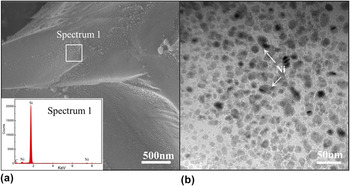
Figure 1 shows the morphology of SiC(Ni) catalyst after reduction by H2 at 400 °C. It can be observed from Fig. 1(a) that the nano-sized Ni catalytic particles were formed and uniformly dispersed on the surface of SiCp. The energy dispersive X-ray spectroscopy (EDS) analysis [inset of Fig. 1(a)] with Ni peaks confirms that the nanoparticles on the surface of SiCp are Ni. Figure 1(b) shows the TEM image of Ni particles on the surface of SiCp and no agglomeration of Ni particles is found. The size of well-dispersed Ni particles ranges from 15 to 30 nm, which is beneficial for growing CNT with narrow distribution of diameters.
Distribution of Ni catalyst on the surface of SiCp: (a) SEM morphology of SiCp(Ni) particles; (b) TEM image of Ni catalytic particles on the surface of SiCp.

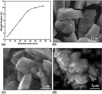
The weight fraction of CNT in hybrid reinforcement was calculated from Eq. (1). Figure 2(a) shows the effect of reaction time on the weight fraction of CNT in SiCp(CNT) hybrid reinforcement. It can be seen that the CNT content increases dramatically with the increment of reaction time during the initial 45 min. After the reaction of 45 min, the CNT content in the hybrid reinforcement increases slowly because that most of SiCp are covered by CNT and there is no space for the growth of CNT, as shown in Fig. 2(d). Figures 2(b)–2(d) show the morphology and distribution of CNT on the surface of SiCp after the reaction time of 15, 30, and 45 min, respectively. As shown in Fig. 2(b), sparse CNTs of 3 wt% disperse on the surface of SiCp after a reaction time of 15 min. As the reaction time increases to 30 min, the CNT content reached to 6 wt% in the hybrid reinforcement. It can be observed from Fig. 2(c) that the surfaces of SiCp were mostly covered by uniformly dispersed CNTs. When the reaction time becomes 45 min, the CNT content reached 9 wt%. The SiCp were hardly seen because it is entirely covered with long CNTs, as seen in the Fig. 2(d). Some SiC particles were agglomerated driven by the entangled long CNTs. The agglomeration of particles has a detrimental effect on the distribution of reinforcements during the fabrication of composites.
(a) The effect of reaction time on the weight of CNT in SiCp(CNT) hybrid reinforcement; the morphology and distribution of CNTs on the surface of SiCp after the reaction time: (b) 15 min, (c) 30 min, (d) 45 min.

Based on the results above, the content and dispersion of CNTs in the SiCp(CNT) hybrid reinforcement can be tuned by adjusting the reaction time. In this work, three types of SiCp(CNT) hybrid reinforcements with CNT content of 3, 6, and 9 wt% were used to fabricate SiCp(CNT)/Al composites. The weight fraction of SiCp(CNT) in each of the three types of composites was equal to 17 wt%. Therefore, the weight fractions of CNT and SiCp in the three types of composites were 0.5 wt% and 16.5 wt% [marked as SiCp(0.5 CNT)/Al], 1 wt% and 16 wt% [noted as SiCp(1 CNT)/Al], 1.5 wt% and 15.5 wt% (signed as SiCp(1.5CNT)/Al), respectively. The detailed constituent of the materials fabricated in this work was provided at Table I and the Al, SiCp/Al, SiCp(0.5 CNT)/Al, SiCp(1 CNT)/Al, and SiCp(1.5 CNT)/Al composites were used in the following part.
Descriptions of samples and results of density measurements.

B. Characterization of SiCp(CNT)/Al composites
Figure 3 shows the optical micrographs of cross-sections of as-extruded 17 wt% SiCp/Al, SiCp(0.5 CNT)/Al, SiCp(1 CNT)/Al, and SiCp(1.5 CNT)/Al composites. For SiCp/Al composites [shown in Fig. 3(a)], the distribution of SiCp in Al matrix is uniform and the specimen exhibits densified microstructure without observable micropores or macroscopic defects. In Figs. 3(b) and 3(c), we can see that the microstructures of SiCp(0.5 CNT)/Al and SiCp(1 CNT)/Al composites are similar to those of SiCp/Al composites. It indicates that the existence of CNT on the surface of SiCp has no apparent effect on the distribution of SiCp(CNT) hybrid reinforcement. However, as shown in Fig. 3(d), there are some aggregate regions (especially marked with dashed circle) in the microstructure of SiCp(1.5 CNT)/Al composites. This is because that SiCp(CNT) hybrid reinforcement with 9 wt% CNT is entangled with each other due to the long length of CNT. So the uniform distribution of SiCp(CNT) hybrid reinforcement is difficult, and the entangled SiCp(CNT) hybrid reinforcement will lead to aggregate in the Al matrix.
The representative optical micrographs of the cross sections of as-extruded composites: (a) SiCp/Al composite; (b) SiCp(0.5 CNT)/Al composite; (c) SiCp(1 CNT)/Al composite; (d) SiCp(1.5 CNT)/Al composite.

In theoretical and experimental bulk densities of Al matrix, the extruded SiCp/Al and SiCp(CNT)/Al composites were listed in Table I. Theoretical and experimental values of Al matrix are almost identical, which confirms that the full-dense samples were fabricated by the forming process. For the extruded SiCp/Al, SiCp(0.5 CNT)/Al, and SiCp(1 CNT)/Al composites [seen in Figs. 3(a)–3(c)], the uniformly dispersed reinforcement and dense microstructure render in their dense samples. This is in accordance with the listed results of their densities at Table I. The aggregate of SiCp(CNT) hybrid reinforcement in SiCp(1.5 CNT)/Al composites impedes the densification of the composite specimens, and thus leads to the decrease of the relative density of the SiCp(1.5 CNT)/Al composite.
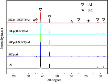
Figure 4 illustrates the XRD results of Al matrix and its composites after extrusion. It can be observed that there is no peak of CNT in all of SiCp(CNT)/Al composites after extrusion, which could be possibly attributed to the low content in the SiCp(CNT)/Al composites. Moreover, the peak of Al4C3 is not identified from the XRD results, which indicated the absence of chemical reaction between Al and reinforcements (CNT or SiCp) in the preparation process of SiCp/Al and SiCp(CNT)/Al composites.
X-ray diffraction characterization of Al matrix, SiCp/Al and SiCp(CNT)/Al composites after extrusion.

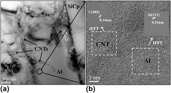
Figure 5 presents the typical TEM images of interfacial characteristic between reinforcement and Al matrix in the SiCp(1 CNT)/Al composites. It can be seen from Fig. 5(a) that the in situ CNTs disperse within the vicinity of the interface between SiCp and Al matrix, and the CNTs are embedded in the matrix during the processing of hot pressing and extrusion. Figure 5(b) shows the HRTEM image of the interface between CNTs and Al [part of Fig. 5(a)] and the insets are the provided inverse fast Fourier transform (IFFT) images of the area of Al and CNT, respectively. The micrograph reveals a clean interface between CNTs and Al matrix, which indicates good interfacial bonding between them. Moreover, CNTs in the composite present perfect structure with apparent graphitic sheets. The structure and integrity of CNTs are well protected because of little damage during fabrication processes of this work. As discussed in the XRD results, no obvious Al4C3 has also been found in the TEM images, which confirms the chemically stability of the well-structured CNT in the composite.
Interfacial characteristic of SiCp(1 CNT)/Al composites: (a) representative TEM images on the interface between SiCp(CNT) reinforcement and Al matrix; (b) HRTEM image of the interface between CNTs and Al matrix, inset shows IFFT images of CNT and Al.

C. Mechanical properties of SiCp(CNT)/Al composites
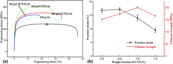
Tensile stress–strain relations of Al matrix, SiCp/Al composites, and three sets of SiCp(CNT)/Al composites are presented in the Fig. 6. The details of their tensile properties are also summarized in Table II. The Young’s modulus (E), yield strength (YS), ultimate tensile strength (UTS), and failure strain (εf) of pure Al matrix are 69 GPa, 79 MPa, 124 MPa, and 23.0% respectively, which are comparable with reported data. Reference Pérez-Bustamante, Gómez-Esparza, Estrada-Guel, Miki-Yoshida, Licea-Jiménez, Pérez-García and Martínez-Sánchez24 The addition of 17 wt% SiCp in the SiCp/Al composite results partly improved tensile properties (e.g., E: 86 GPa, YS: 98 MPa, and UTS: 152 MPa) with a remarkable reduction in ductility (εf: 16.8%). In Fig. 6(a), with the introduction of SiCp(CNT) hybrid reinforcement, the SiCp(CNT)/Al composites exhibit the further enhancement in tensile strength as well as failure strain compared with those of SiCp/Al composite. It is seen from Fig. 6(b) and Table II that the CNT content in SiCp(CNT) hybrid reinforcement has a significant effect on the mechanical properties of SiCp(CNT)/Al composites. Compared to the pure Al matrix, the E, YS, and UTS of SiCp(0.5 CNT)/Al composite increase to 91 GPa, 110 MPa, and 175 MPa, improving by 30%, 39%, and 41%, respectively. Besides, the fracture strain εf is 17.7%, which is even better than that of SiCp/Al composite. With the increased CNT content, SiCp(1 CNT)/Al exhibits the best improvement of E, YS, and UTS, which are 95 GPa, 120 MPa, and 201 MPa (36%, 52%, and 76% higher than those of pure Al matrix), respectively. When the CNT content increased to 1.5 wt% in the SiCp(1.5 CNT)/Al composites, however, the tensile properties E, YS, and UTS decrease to 94 GPa, 100 MPa, and 166 MPa, respectively. The aggregation of SiCp(CNT) reinforcement loses load bearing capability during the tensile process resulting in the little improvement in their tensile properties.
(a) Tensile stress–strain relations of composite materials fabricated in this study; (b) comparison of the ultimate strength and fracture strain of various composites reinforced by different content of CNT.

Summary of mechanical properties of pure Al matrix and composites. Three tensile tests were made for each set of samples and the value is meaning standard deviations (±SD) based on the three tensile results of each sample category.

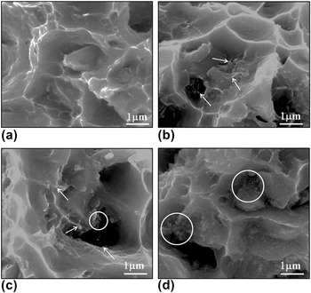
Figures 7(a)–7(d) display the fractographs of SiCp/Al, SiCp(0.5 CNT)/Al, SiCp(1 CNT)/Al, and SiCp(1.5 CNT)/Al composites, respectively. As shown in Fig. 7(a), the fracture surface of SiCp/Al composite consists of ductile and brittle fracture features. These areas with small dimples and tearing ridges are related to the Al matrix, and larger dimples are associated with the decohesion between SiCp and the matrix. As shown in Figs. 7(b)–7(d), the fractographs of SiCp(CNT)/Al composites have the similar features with two distinct parts. However, there are some different characteristics in the larger dimples due to the existing CNTs. In the SiCp(0.5 CNT)/Al composites, the individual breaking and pulling out of CNTs are observed inside larger dimples [as marked with arrows in Fig. 7(b)], which proves that all of CNTs are incorporated into the Al matrix at the interfaces between SiCp and Al after extrusion. Therefore, the effective load bearing and more expending energy during pulling out of CNT account for the better tensile properties of SiCp(0.5 CNT)/Al composites. Moreover, due to embedded CNTs, weak interfaces between SiCp and Al are enhanced, which inhibits the initiation of crack in the interface. For the SiCp(1 CNT)/Al composite as shown in the Fig. 7(c), more CNTs are observed in the larger dimples. But, as marked with white circle in the Fig. 7(c), CNT aggregations formed in the SiCp(CNT) hybrid reinforcement are not incorporated tightly with Al matrix, which gives rise to premature failure of these regions and degrades the ductility of the composites. As shown in the Fig. 7(d), most of the CNTs are clustered in the interface (as marked with white circles), which cannot work as effective reinforcement resulting in the dramatical decreases of strength and ductility of SiCp(1.5 CNT)/Al composite.
SEM images of SiCp/Al and SiCp(CNT)/Al composites’ fractograph: (a) SiCp/Al; (b) SiCp(0.5 CNT)/Al; (c) SiCp(1 CNT)/Al; (d) SiCp(1.5 CNT)/Al.

D. Strengthening mechanism of SiCp(CNT)/Al composites
As discussed in the previous studies, Reference Suh, Joshi and Ramesh25–Reference Kurita, Estili, Kwon, Miyazaki, Zhou, Silvain and Kawasaki29 the strength increasing of particle reinforced AMCs over the matrix results from the direct and secondary strengthening by the introduction of ceramic reinforced particles. The direct strengthening is the contribution of the load transferring from the matrix to the reinforcement via shear stresses at the interface between the components, and the secondary strengthening is the strain hardening of the matrix caused by the introduction of the reinforcement. It is because that abundant geometrically necessary dislocations are formed in the matrix adjacent to the interface due to the mismatch in elastic modulus and coefficients of thermal expansion between the reinforcement and the matrix.
Therefore, the predicted yield strength of the composites fabricated in this study can be expressed as Reference Kai, Li, Fan, Guo, Xiong, Zhang, Su, Lu, Moon and Zhang26 :
 $${\sigma _{{\rm{cy}}}} = {\sigma _{{\rm{matrix}}}} + \Delta \sigma _{\rm{r}}^{{\rm{dis}}} + \Delta \sigma _r^{{\rm{L}} - {\rm{T}}}\quad .$$
Where
 $\Delta \sigma _{\rm{r}}^{{\rm{dis}}}$
is the strengthening term of matrix due to the formation of geometrically necessary dislocations;
 $\Delta \sigma _{\rm{r}}^{{\rm{L - T}}}$
is the load-transfer strengthening term of reinforcement, which can be evaluated by the modified shear lag model as
Reference Suh, Joshi and Ramesh25,Reference Nardone27,Reference Tang, Anderson, Gnaupel-Herold and Prask28
 $$\Delta \sigma _{\rm{r}}^{{\rm{L - T}}} = 0.5{\sigma _{{\rm{my}}}}fs$$
and
 $${\sigma _{{\rm{my}}}} = {\sigma _{{\rm{matrix}}}} + \Delta \sigma _{\rm{r}}^{{\rm{dis}}}\quad .$$
Combined with Eqs. (3) and (4), Eq. (2) can be expressed as:
 $${\sigma _{{\rm{cy}}}} = {\sigma _{{\rm{my}}}}(1 + 0.5fs)\quad .$$
Where σmy, f, and s are the yield strength of Al matrix, the volume fraction of reinforcement, and the aspect ratio of reinforcement, respectively.
For the SiCp/Al composite, the reinforcement (SiCp) is polygon and has the same sizes of diameter and height, so s is equal to 1.0 for SiCp in this study. The volume fraction of reinforcement f can be calculated from the following equation:
 $${f_{{\rm{SiCp}}}} = {{{{{{\bi{m}}_{{\rm{SiCp}}}}} \over {{\rho _{{\rm{SiCp}}}}}}} \over {{{{{\bi{m}}_{{\rm{SiCp}}}}} \over {{\rho _{{\rm{SiCp}}}}}} + {{{{\bi{m}}_{{\rm{Al}}}}} \over {{\rho _{{\rm{Al}}}}}}}}$$
where the density of SiCp (ρSiCp) and Al (ρSiCp) are 3.2 and 2.7 g/cm3, respectively. The weight fraction of SiCp (m SiCp) and Al (m Al) are 17 wt% and 83 wt% in the SiCp/Al composite. So the volume fraction of SiCp (f SiCp) is equal to 14.7 vol% in the SiCp/Al composite. Assuming the actual strengthening effect of SiCp can be well represented by the value of σmy = σexperiment = 98 MPa. Then, the yield strength of matrix σmy in the SiCp/Al composite can be determined to 91.3 MPa.
For the SiCp(CNT)/Al composites fabricated under the same condition with SiCp/Al composite, the size of SiCp(CNT) hybrid reinforcement has almost no change and is identical to that of SiCp. Therefore, we assume the effect of SiCp(CNT) hybrid reinforcement on the yield strength of matrix is the same as that of SiCp. The yield strength of matrix σmy in the SiCp(CNT)/Al composite is also preferred as 91.3 MPa. So the increment of yield strength of SiCp(CNT)/Al composites, compared to SiCp/Al composites, is mainly from the load-transfer strengthening of CNT. The CNT content f CNT in SiCp(CNT)/Al composites can be expressed as:
 $${f_{{\rm{CNT}}}} = {{{{{{\bi{m}}_{{\rm{CNT}}}}} \over {{\rho _{{\rm{CNT}}}}}}} \over {{{{{\bi{m}}_{{\rm{CNT}}}}} \over {{\rho _{{\rm{CNT}}}}}} + {{{{\bi{m}}_{{\rm{SiCp}}}}} \over {{\rho _{{\rm{SiCp}}}}}} + {{{{\bi{m}}_{{\rm{Al}}}}} \over {{\rho _{{\rm{Al}}}}}}}}$$
where ρCNT = 2 g/cm3 (Ref. Reference Yang, Shi, He, Liu, Li and Zhao22) is the density of CNT. The weight fraction of CNT (m
CNT), SiCp (m
SiCp), and Al (m
Al) can be acquired from Table I for SiCp(0.5 CNT)/Al, SiCp(1 CNT)/Al, and SiCp(1.5 CNT)/Al composites. Thus, f
CNT in these three composites are estimated to 0.69 vol%, 1.37 vol%, and 2 vol%, respectively. The ratio of length to outer diameter of CNT (s) can be measured from Fig. 2, and its value is determined to 50 for the synthesized CNT in our work. Consequently, according to Eq. (3), the load-transfer strengthening of CNT
 $\Delta \sigma _{{\rm{CNT}}}^{{\rm{L - T}}}$
is estimated to be 15.7, 31.3, and 45.6 MPa for the SiCp(0.5 CNT)/Al, SiCp(1 CNT)/Al, and SiCp(1.5 CNT)/Al composites, respectively. At the same time, the yield strengths of the composites σcy are calculated and expected to 113.7, 129.3, and 143.6 MPa for the SiCp(0.5 CNT)/Al, SiCp(1 CNT)/Al, and SiCp(1.5 CNT)/Al composites, respectively. However, as listed in Table II, just the experimental yield strength of SiCp(0.5 CNT)/Al composite of 110 MPa is close to the calculated value. Experimental yield strengths of SiCp(1 CNT)/Al and SiCp(1.5 CNT)/Al composites are much lower than the expected results, which should be mainly caused by the agglomeration of CNT and not incorporated with Al matrix.
IV. CONCLUSIONS
In this paper, SiCp(CNT)/Al composites were fabricated via in situ CVD synthesis and conventional powder metallurgy. Effects of CNT content on the morphology of SiCp(CNT) hybrid reinforcement, the microstructural characterization, and the tensile mechanical properties of SiCp(CNT)/Al composites were studied. Meanwhile, they were discussed and compared to those of SiCp/Al composite with the same weight fraction of reinforcement. The contributions of SiCp and CNT to the improvement of mechanical properties of SiCp(CNT)/Al composites were also reported. The main conclusions are provided as the following:
-
(1) SiCp(CNT) hybrid reinforcement with various CNT contents of 3, 6, and 9 wt% was successfully synthesized under the reaction time of 15, 30, and 45 min, respectively. It was found that the morphology of SiCp(CNT) hybrid reinforcement with 6 wt% CNT was the most suitable result with uniformly dispersed CNTs on the surface of SiCp.
-
(2) SiCp(CNT)/Al composite exhibited the better strengthening effect compared to the SiCp/Al composite with the same content of reinforcement. SiCp(0.5 CNT)/Al composite indicated simultaneously enhanced tensile strength and ductility than those of SiCp/Al composites, while SiCp(1 CNT)/Al composite showed the best enhancements of Young’s modulus and tensile strength that are 36% and 76% higher than those of Al matrix, respectively.
-
(3) The enhancement in the mechanical properties of composites was attributed to the homogeneous dispersion of SiCp(CNT) hybrid reinforcement and well-structure CNTs on the surface of SiCp embedded tightly with the Al matrix that could ensure the effective load bearing of CNT. Moreover, the discrepancy between calculated and experimental strengthening contributions of CNT to the yield strength of SiCp(1.5 CNT)/Al composite was attributed to the agglomeration of CNT and not incorporated with Al matrix.
ACKNOWLEDGMENTS
The authors would like to sincerely acknowledge the financial supports of the National Natural Science Foundation of China (Nos. 51471106, 51501111), the National Basic Research Program (973Program) (No. 2012CB619600), and the Foundation of Shanghai Science and Technology Committee of China (Nos. 14DZ2261200, 14520710100).