Introduction
Microstrip antennas loaded by metallic vias have been widely employed in the antennas and propagation scientific community for several decades [Reference Schaubert, Farrar, Sindoris and Hayes1, Reference Richards and Long2] and continue to be the subject of recent studies [Reference Liu, He and Li3–Reference Gao, Zhang, Dong, Dou, Yu and Hu6]. Embedded metallic vias offer versatility in antenna design and find applications in various contexts. Reconfigurable Antennas: In this group, tunable components such as varactors [Reference Nguyen-Trong, Hall and Fumeaux4, Reference Han, Wang and Dong5, Reference Qin, Wei and Guo7] and p-i-n diodes [Reference Richards and Long2, Reference Gao, Zhang, Dong, Dou, Yu and Hu6, Reference Chen, Wei, Qin, Guo and Chen8] are connected to the patch through metallic vias, enabling adjustments of the antenna parameters. Perturbations: Metallic vias are employed to change the characteristics of patch antennas, achieving multiband operation and modified radiation patterns [Reference Nunes, Moleiro, Rosa and Peixeiro9–Reference Huang, Guo, Li, Xu and Ding12]. Substrate Integrated Waveguide: Shorting pins are employed to realize electric walls, enabling the development of compact radiators with enhanced performance [Reference Tang, Wang, Yu, Yang and Chen13–Reference Dos Santos Silveira, Antreich and Do Nascimento15]. Small Antennas: The combination of shorting pins and reactive terminations is effective in reducing the radiator dimensions [Reference Han, Wang and Dong5, Reference Fong and Chair10].
The analysis of microstrip antennas loaded by metallic pins traditionally relies on computationally intensive full-wave simulations, which require significant processing and memory resources. In this context, there is a growing interest in employing fast analytical techniques to provide designers with initial geometries and performance estimates before using full-wave tools [Reference Huang, Guo, Li, Xu and Ding12, Reference Chapari, Zeidaabadi Nezhad and Firouzeh16, Reference Richards and Lo17].
This letter introduces an improved analytical method for analyzing rectangular microstrip antennas loaded by metallic vias with lumped terminations. The formulation is based on the analysis of an n-port resonant cavity [Reference Richards and Lo17] by means of the eigenfunction expansion method. It is worth noting that [Reference Richards and Lo17] has primarily focused on computing resonant frequencies and input impedance of linearly polarized (LP) patches. In contrast, our work emphasizes a model capable of computing radiation patterns and enabling multimode operation, including circularly polarized (CP) patches. This approach offers a low computational cost and good accuracy, making it a valuable predesign tool for estimating initial geometry and antenna performance. Moreover, it provides designers with physical insights into the radiator’s operation.
The novelties of this letter are as follows:
(i) A Strategy for the Radiated Far-Field Computation: The proposed model incorporates the superposition of non-resonant modes to represent the field of a perturbed cavity. This technique allows, for example, comprehensive analysis of the radiated fields of antennas operating in  $TM_{00}$ mode [Reference Liu, Zhu and Liu11, Reference Huang, Guo, Li, Xu and Ding12] and simplifies the examination of circular polarization in perturbed antennas [Reference Schaubert, Farrar, Sindoris and Hayes1].
(ii) Multiband Operation Analysis: The model offers insights into the performance of multiband antennas [Reference Richards, Davidson and Long18], through the effects of non-resonant modes on input impedance.
(iii) Application in Reconfigurable Antenna: The proposed method is a useful tool for the predesign of reconfigurable patch antennas [Reference Sung19, Reference Pyo and Shin20], providing robust support for future advancements in this area.
This letter begins by detailing the formulation of the P-port cavity model. Afterward, the designs of CP and LP antennas are demonstrated and compared with results obtained from HFSS software. Finally, to further validate the model, a prototype of a polarization reconfigurable antenna is manufactured and tested.
Antenna modeling
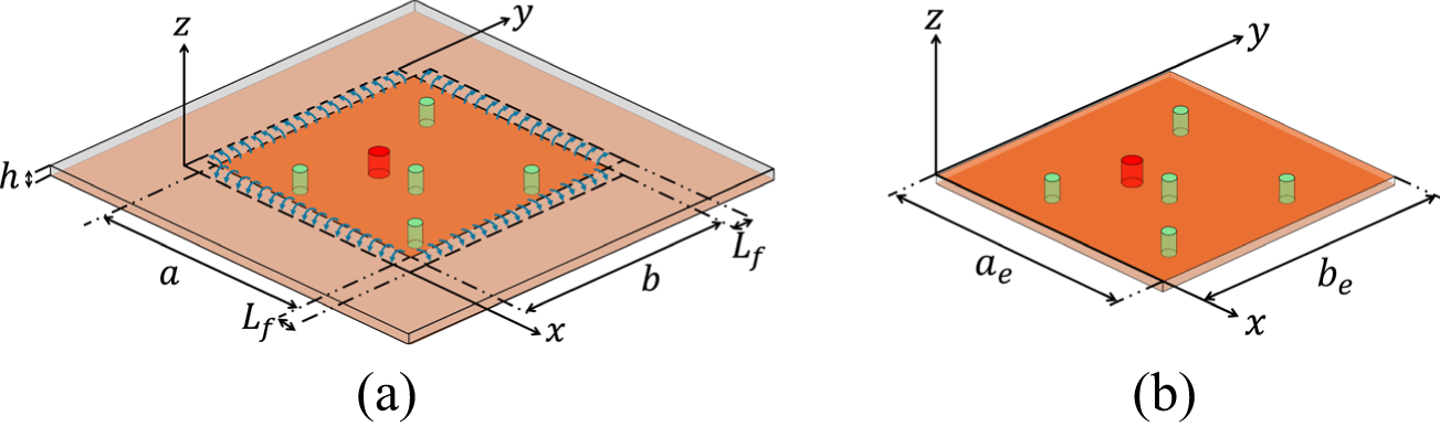
The proposed antenna geometry, depicted in fig. 1(a), is based on the canonical rectangular form (a × b) printed on a low-loss substrate of thickness h. The radiator includes a ground plane and a set of metallic pins positioned vertically within the substrate. These pins can be used to connect the patch either to the ground plane or to grounded components such as inductors, capacitors, varicaps, or p-i-n diodes. The antenna is fed by a coaxial probe, illustrated as the red pin. Consistently, the fringing fields are represented in the geometry with a length Lf at the edges of the patch [Reference Hammerstad21].
Microstrip antenna loaded by metallic vias. (a) Proposed geometry. (b) Equivalent resonant cavity.

In this work, the antenna is modeled by an equivalent resonant cavity [Reference Richards, Yuen and Harrison22], as illustrated in fig. 1(b). The cavity, with dimensions ae × be, where ae = a + 2Lf and be = b + 2Lf, consists of two electric walls (patch and ground plane) and four magnetic walls around the periphery. The feed probe and the metallic pins are modeled as strips with uniform electric current densities  ${\skew5\vec J_{fp}}$. In this way, the problem can be interpreted as a P-source cavity or equivalently a P-port circuit.
The analysis of the antenna is divided into three main parts: (a) computing the electromagnetic field inside the cavity; (b) evaluating the far field; and (c) determining the input impedance.
Electric field in the equivalent cavity
For electrically thin antennas, i.e., those whose thickness h is significantly smaller than the wavelength λ in the substrate, the electric field in the equivalent cavity exhibits only the Ez component, which can be written using modal expansion as [Reference Richards, Yuen and Harrison22]
 \begin{equation}{E_z}\left( {x,y} \right) = \mathop \sum \limits_{m = 0}^\infty \mathop \sum \limits_{n = 0}^\infty {E_{mn}}{\Psi _{mn}}\left( {x,y} \right),\end{equation}
where  ${E_{mn}}$ is the amplitude of each
 ${\text{TM}}_{mn}^z$ mode and
 ${\Psi _{mn}}\left( {x,y} \right) = {\text{cos}}\left( {m\pi x/{a_e}} \right){\text{cos}}\left( {n\pi y/{b_e}} \right)$.
The amplitude  ${E_{mn}}$ is computed from the solution to the nonhomogeneous wave equation
 $({\nabla ^2} + {k^2}){\text{ }}{E_z} = j\omega {\mu _0}{\skew5\vec J}_f \cdot \skew3\hat{z}$:
 \begin{equation}{E_{mn}} = \frac{{j\omega {\mu _0}{\text{ }}{\mathop \iint \nolimits_S}{J_f}\Psi _{mn}^*\left( {x,y} \right){\text{ }}ds{\text{ }}}}{{\left( {{k^2} - k_{mn}^2} \right){\mathop \iint \nolimits_S}{{\left| {{\Psi _{mn}}\left( {x,y} \right)} \right|}^2}ds{\text{ }}}}{\text{,}}\end{equation}
where  $S$ denotes the cavity surface located in the xy-plane,
 ${\skew5\vec J}_f$ is the total current density comprised of P sources representing the feed probe and metallic pins,
 ${k_{mn}} = \sqrt {{{\left( {m\pi /{a_e}} \right)}^2} + {{\left( {n\pi /{b_e}} \right)}^2}} $ is the resonant wavenumber, and
 $k = \omega \sqrt {{\mu _0}{\varepsilon _r}{\varepsilon _0}} $ is the wavenumber in a lossless cavity.
The pth source of current density amplitude J 0p ( $1 \leqslant p \leqslant {\text{ }}P$) is modeled as a strip with width Lp [Reference Garg and Bahl23] and height h, centered at the coordinates (xp, yp). Therefore, the total current density
 ${\skew5\vec J}_f$ is given by
 \begin{equation}{\skew5\vec J}_f\left( {x,y} \right) = \mathop \sum \limits_{p = 1}^P {J_{fp}}\left( {x,y} \right)\skew3\hat{z} = \mathop \sum \limits_{p = 1}^P {J_p}\left( y \right)\delta \left( {x - {x_p}} \right)\skew3\hat{z},\end{equation}
where
 \begin{equation}{J_p}\left( y \right) = \bigg\{ \begin{array}{*{20}{c}}
{{J_{0p}}{\text{, if }}\left| {y - {y_p}} \right| \leqslant {L_p}/2} \\
{0{\text{, elsewhere }}}
\end{array}.\end{equation}
After substituting (3) into (2) and evaluating the double integrals, the amplitude of each mode is written as
 \begin{equation}{E_{mn}} = \frac{{j\omega {\mu _0}}}{{{a_e}{b_e}}}\frac{{{\xi _m}{\xi _n}\mathop \sum \nolimits_{p = 1}^P{J_{0p}}{L_p}{\Psi _p}{\text{ }}}}{{{k^2} - k_{mn}^2}}{\text{,}}\end{equation}
where  ${\Psi _p} = {\text{cos}}\left( {m\pi {x_p}/{a_e}} \right){\text{cos}}\left( {n\pi {y_p}/{b_e}} \right){\text{sinc}}\left( {n\pi {L_p}/2{b_e}} \right)$, with
 ${\xi _\tau } = 1$, if
 $\tau = 0$, and
 ${\xi _\tau } = 2$, otherwise, and
 ${\text{sinc}}\left( x \right) = {\text{sin}}\left( x \right)/x$.
Finally, applying (5) in (1), the electric field inside the cavity is established as a function of the current densities  ${J_{fp}}$.
Far field
Using the magnetic surface currents on the magnetic walls of the equivalent cavity, the far-zone radiated field by the microstrip antenna can be computed by applying the Equivalence Principle and the electric vector potential [Reference Lo, Solomon and Richards24]. The expressions for the far-field components  ${E_\theta }_{mn}\left( {\theta ,\phi } \right)$ and
 ${E_\phi }_{mn}\left( {\theta ,\phi } \right)$ for the
 ${\text{TM}}_{mn}^z$ modes are well-established in the literature [Reference Lumini, Cividanes and da S. Lacava25, Reference James and Wood26] and are not detailed here.
The radiation pattern of a canonical rectangular microstrip antenna is often well characterized by the  ${\text{TM}}_{01}^z$ or
 ${\text{TM}}_{10}^z$ modes in LP designs. In contrast, for CP radiators, the superposition of these two modes adequately represents the far field. However, in this work, due to the multiple sources within the cavity, a strong dependence on several modes to describe the
 ${E_z}$ field, as given by (1), is observed. As a result, the far field can be accurately described only if the radiated fields by each
 ${\text{TM}}_{mn}^z$ mode are superimposed. Thus,
 \begin{equation}{E_\theta }\left( {\theta ,\phi } \right) = \mathop \sum \limits_{m = 0}^\infty \mathop \sum \limits_{n = 0}^\infty {E_\theta }_{mn}\left( {\theta ,\phi } \right),\end{equation}
 \begin{equation}{E_\phi }\left( {\theta ,\phi } \right) = \mathop \sum \limits_{m = 0}^\infty \mathop \sum \limits_{n = 0}^\infty {E_\phi }_{mn}\left( {\theta ,\phi } \right),\end{equation}
The dependency on the number of modes to describe the radiated fields (6) and (7), as well as the input impedance will be further explored in Section III–A.
Input impedance
The complex power delivered by the pth source to the cavity can be calculated using the complex Poynting’s theorem as  ${P_{in}}_p = - \frac{1}{2}\int\int\int\limits_V {E_z} J_{fp}^*dv$. Hence, the total complex power delivered to the cavity is obtained by summing the powers delivered by all sources. According to the circuit theory, the power supplied by the pth source is
 ${P_{in}}_p = \frac{1}{2}{Z_{in}}_p{\left| {{I_{in}}_p} \right|^2}$, leading to the input impedance of the pth port:
 \begin{equation}{Z_{in}}_p = - \frac{1}{{{{\left| {{I_{in}}_p} \right|}^2}}} \int\int\int\limits_V {E_z}J_{fp}^*dv,\end{equation}
where  ${I_{in}}_p = {J_{0p}}{L_p}$ is the complex current on the pth source.
Substituting (1) and (5) into (8) and evaluating the triple integral yields the input impedance of the pth port:
 \begin{equation}{Z_{in}}_p = \frac{{ - j\omega {\mu _0}h}}{{{a_e}{b_e}}}\mathop \sum \limits_{q = 1}^P \frac{{{I_{in}}_q}}{{{I_{in}}_p}}\mathop \sum \limits_{m = 0}^\infty \mathop \sum \limits_{n = 0}^\infty \frac{{{\xi _m}{\xi _n}\Psi _p^2}}{{{k^2} - k_{mn}^2}}{\text{.}}\end{equation}
Modeling the cavity as a P-port linear circuit, represented by a  $\left[ Z \right]$ matrix of elements
 ${Z_{pq}}$, the voltage on the pth port is given by
 ${V_{in}}_p = \mathop \sum \limits_{q = 1}^P {Z_{pq}}{I_{in}}_q$. Then, the input impedance of the pth port is
 ${Z_{in}}_p = \mathop \sum \limits_{q = 1}^P {Z_{pq}}{I_{in}}_q/{I_{in}}_p$. This leads to the following expression for the element
 ${Z_{pq}}$:
 \begin{equation}{Z_{pq}} = \frac{{ - j\omega {\mu _0}h}}{{{a_e}{b_e}}}\mathop \sum \limits_{m = 0}^\infty \mathop \sum \limits_{n = 0}^\infty \frac{{{\xi _m}{\xi _n}\Psi _p^2}}{{{k^2} - k_{mn}^2}}{\text{.}}\end{equation}
Up to this point, we have assumed that the antenna has P ports. We impose that port 1 corresponds to the feed probe, while the others are terminated with loads  ${Z_L}_q$, and without loss of generality, assuming
 ${I_{in}}_1 = 1{\text{ A}}$, the following linear system is found:
 \begin{align}
&\left[ {\begin{array}{*{20}{c}}
{{Z_{22}} + {Z_L}_2}&{{Z_{23}}}& \ldots &{{Z_{2P}}} \\
{{Z_{32}}}&{{Z_{33}} + {Z_L}_3}& \ldots &{{Z_{3P}}} \\
\vdots & \vdots & \ddots & \vdots \\
{{Z_{P2}}}&{{Z_{P3}}}& \ldots &{{Z_{PP}} + {Z_L}_P}
\end{array}} \right].\left[ {\begin{array}{*{20}{c}}
{{I_{in}}_2} \\
{{I_{in}}_3} \\
\vdots \\
{{I_{in}}_P}
\end{array}} \right] \nonumber\\
&\quad = \left[ {\begin{array}{*{20}{c}}
{ - {\text{ }}{Z_{21}}} \\
{ - {\text{ }}{Z_{31}}} \\
\vdots \\
{ - {\text{ }}{Z_{P1}}}
\end{array}} \right].\end{align}
The currents  ${I_{in}}_q$ are determined by solving (11), and consequently, the antenna input impedance is calculated as
 ${Z_{in}}_1 = \mathop \sum_{q = 1}^P {Z_{1q}}{I_{in}}_q$. These currents play a crucial role in computing (5) and subsequently in determining the far field described in (6) and (7).
Effective loss tangent
The effects of radiated power  ${P_i}$, metallic loss
 ${P_c}$, and dielectric loss
 ${P_d}$ are computed and incorporated into the model using the effective loss tangent concept [Reference Richards, Yuen and Harrison22]. This parameter is calculated for each
 ${\text{TM}}_{mn}^z$ mode as
 ${\delta _{ef}}_{mn} = \left( {{P_i} + {P_c} + {P_d}} \right)/\left( {2{\omega _{mn}}{\text{ }}{W_e}_{mn}} \right)$, where
 ${\omega _{mn}}$ is the angular resonant frequency given by
 ${\omega _{mn}} = {c_0}{k_{mn}}/\sqrt {{\varepsilon _r}} $, and
 ${\text{ }}{W_e}_{mn}$ represents the stored electric energy in the cavity for each mode. Therefore, the effective wavenumber of each mode is computed as
 ${k_{ef}}_{mn} = k{\left( {1 - j{\text{ }}{\delta _{ef}}_{mn}} \right)^{1/2}}$, which replaces
 $k$ in (2), (5), (9), and (10), properly incorporating the losses into the model. The surface wave loss is ignored in
 ${\delta _{ef}}_{mn}$ due to its negligible effect on electrically thin antennas [Reference Lo, Solomon and Richards24].
The challenge of computing  ${\delta _{ef}}_{00}$ of the
 ${\text{TM}}_{00}^z$ mode is a known issue in the literature [Reference Garg and Bahl23], which seems not clearly solved yet. In this study, we address this challenge by employing the following rule:
 ${\delta _{ef}}_{00} = {\delta _{ef}}_{10}$, if ae > be, or
 ${\delta _{ef}}_{00} = {\delta _{ef}}_{01}$, if ae < be. The accuracy of this choice is demonstrated in the next section. Furthermore, the computation of
 ${\delta _{ef}}_{mn}$ is conducted for the unloaded antenna, similar to a classical rectangular microstrip patch [Reference Lo, Solomon and Richards24].
Validation of the proposed model and case study
To validate the proposed model, we analyze two antennas: one with grounded capacitors and the other with shorted metallic vias. We compare the results obtained from our model with those generated by the HFSS simulator.
Circularly polarized antenna
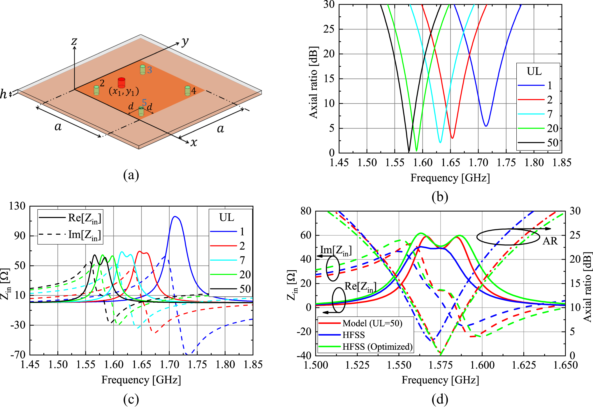
Initially, we analyze the CP antenna illustrated in fig. 2(a). It consists of a square patch with a side length a = 37.19 mm (ae = 40.25 mm) and a 50 Ω probe positioned at x 1 = 11.3 mm and y 1 = a/2. Four metallic pins with a radius of 0.5 mm are placed at a distance d = 2.0 mm from the antenna corners, connecting grounded capacitors to the patch. The antenna is printed on a laminate with a thickness of 3.048 mm, characterized by a relative permittivity εr = 2.55 and loss tangent tan δ = 0.002. For proper CP operation at 1.575 GHz, the capacitances, acting as perturbations in the cavity, are tuned as follows: capacitances C 1 = 1.346 pF are connected in vias 2 and 4, resulting in ZL 2 = ZL 4 = —j75 Ω. Similarly, capacitances C 2 = 1.296 pF are connected in vias 3 and 5, leading to ZL 3 = ZL 5 = —j78 Ω.
CP antenna loaded by capacitors. (a) Geometry. (b) Axial ratio. (c) Input impedance. (d) Comparisons with HFSS.

These values were obtained through the following systematic procedure. First, all four capacitances were initially set to 1.3 pF, providing an intermediate capacitive reactance within the range offered by the chosen varicap BB833 from Infineon Technologies. Next, the equivalent side length ae was adjusted to achieve a resonance close to the target operating frequency of 1.575 GHz, resulting in a LP antenna at this stage. Finally, a parametric study was conducted to determine the values of C 1 and C 2. This analysis involved slight variations to the initial capacitances, allowing for the optimization of the antenna’s circular polarization performance.
The choice of the upper limit (UL) for the indexes m and n in the summations is crucial for the performance of the proposed model. This aspect is examined by computing the input impedance of the proposed antenna. Assuming the same UL for both m and n, we calculate the broadside axial ratio (AR) [Reference Balanis27] and input impedance for different values of UL, as shown in fig. 2(b) and (c), respectively. Initially, with UL = 1, a resonance at approximately 2.3 GHz would be expected for the unloaded cavity. However, due to the capacitive loading of the vias and the coupling of the modes, the antenna resonates at nearly 1.71 GHz (blue curves in fig. 2(c)). When UL tends to 50, both the input impedance and AR converge (black curves) and exhibit the performance of a CP antenna. This analysis suggests that the two resonant modes depicted by the black curves in fig. 2(c) are strongly influenced by the modes of the unloaded cavity that resonate away from the operating frequency.
To validate our analysis, we simulated the antenna using HFSS. The comparison, illustrated in fig. 2(d), demonstrates a close agreement for both input impedance and broadside axial ratio. Next, tuning the capacitances and the probe position in HFSS (C 1 = 1.405 pF, C 2 = 1.325 pF, and x 1 = 9.5 mm), the results closely matched those obtained from the cavity model. The updated load impedances are ZL 2 = ZL 4 = —j72 Ω and ZL 3 = ZL 5 = —j76 Ω. Note that only minor adjustments were necessary to achieve the final geometry, highlighting the potential of the model as a predesign tool.
Antenna operating in the TM00 mode
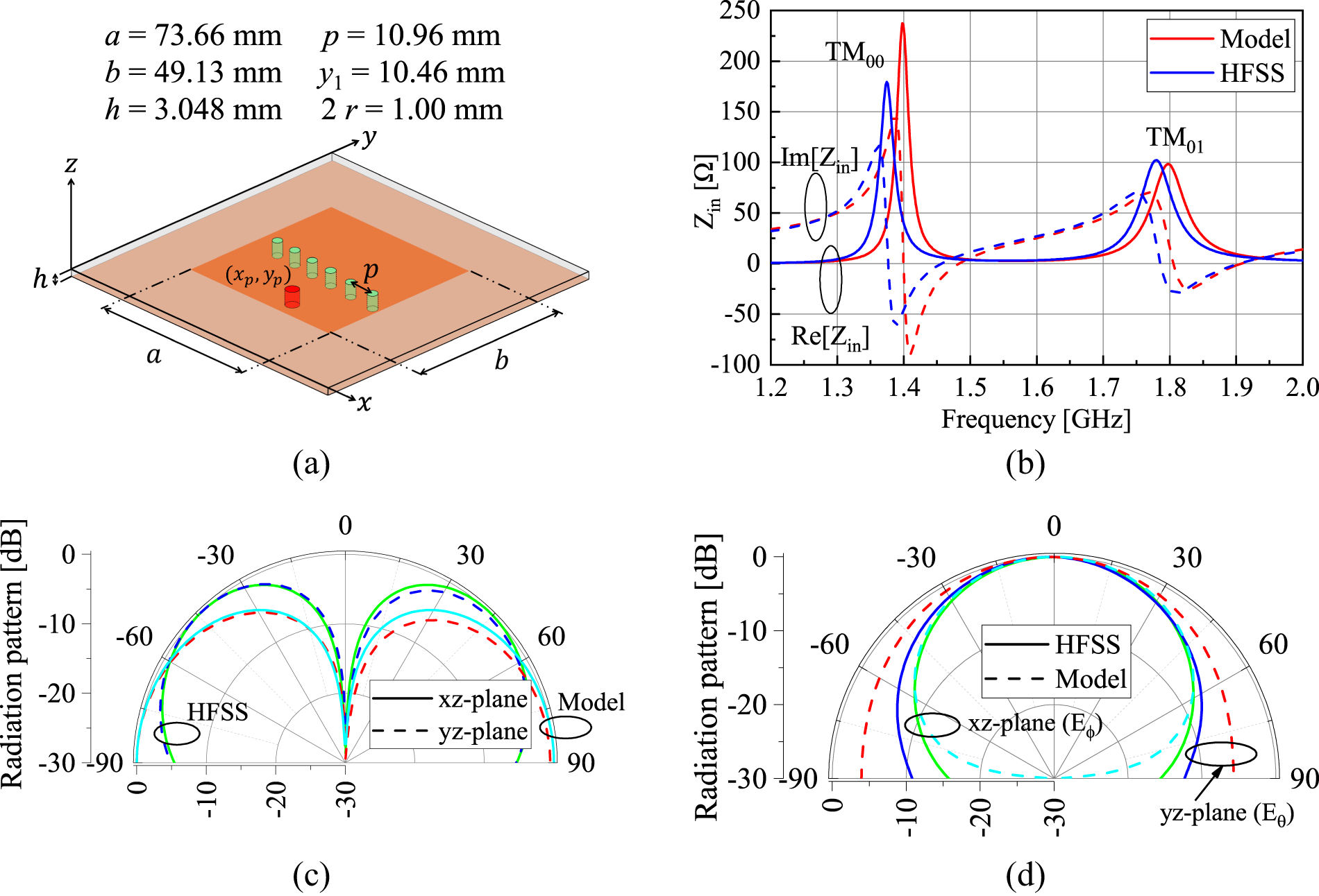
The antenna operating in the  ${\text{TM}}_{00}^z$ mode is a well-known radiator based on shorting pins, renowned for its monopole-like radiation pattern [Reference Nunes, Moleiro, Rosa and Peixeiro9, Reference Fong and Chair10]. To evaluate the effectiveness of our formulation, we analyzed the antenna depicted in fig. 3(a) and assumed UL = 50 in the sums. Following the methodology described in [Reference Liu, Zhu and Liu11], the radiator is designed for dual-band resonance. The lower band is governed by the
 ${\text{TM}}_{00}^z$ mode, with a resonant frequency close to 1.4 GHz, while the upper band is controlled by the
 ${\text{TM}}_{01}^z$ mode, close to 1.8 GHz. The design is conducted using the microwave laminate mentioned earlier, and the final dimensions are listed in fig. 3(a). Comparisons with HFSS for input impedance versus frequency and the radiation pattern in both bands are presented in fig. 3(b), (c), and (d), demonstrating good agreement. The slight deviation in the resonant mode at 1.4 GHz may be attributed to challenges in characterizing the loss tangent of the
 ${\text{TM}}_{00}^z$ mode, as mentioned above.
Dual mode antenna loaded by metallic vias. (a) Geometry. (b) Input impedance. (c) Radiation pattern  ${\text{TM}}_{00}^z$. (d) Radiation pattern
 ${\text{TM}}_{01}^z$.

According to our formulation, the resonance at 1.4 GHz is strongly influenced by neighboring resonant modes, suggesting a perturbed mode with an  ${E_z}$ field distribution similar to
 ${\Psi _{00}}$. Hence, this resonance was classified as
 ${\text{TM}}_{00}^z$. It is important to note that there is no resonant frequency associated with
 ${k_{00}}$. Moreover, as the pins are positioned along the region of the null of
 ${\Psi _{01}}$, the resonance at 1.8 GHz remains unaffected by the presence of the pins and is controlled by the unloaded
 ${\text{TM}}_{01}^z$ mode.
Prototype
The final stage of validating the analytical model involves constructing a reconfigurable CP antenna operating at 1.575 GHz (GPS L1 band). This antenna, based on the geometry presented in Section III–A, is designed to switch between RHCP and LHCP, which is useful for GNSS reflectometry [Reference Asgarimehr, Hoseini, Semmling, Ramatschi, Camps, Nahavandchi, Hass and Wickert28]. Reconfigurability is achieved using four varicap diodes BB833 to synthesize the loads ZLp .
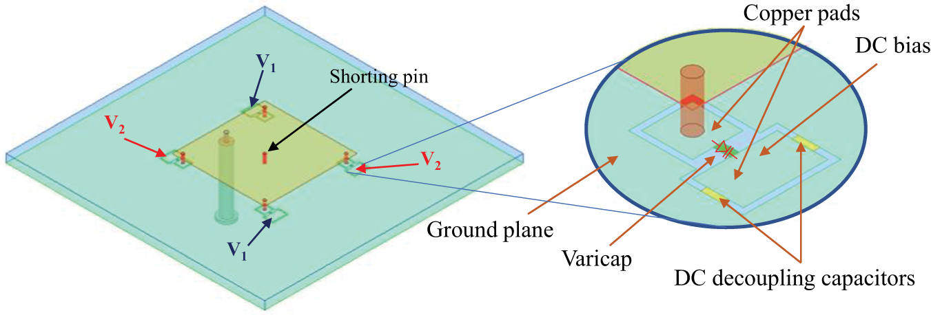
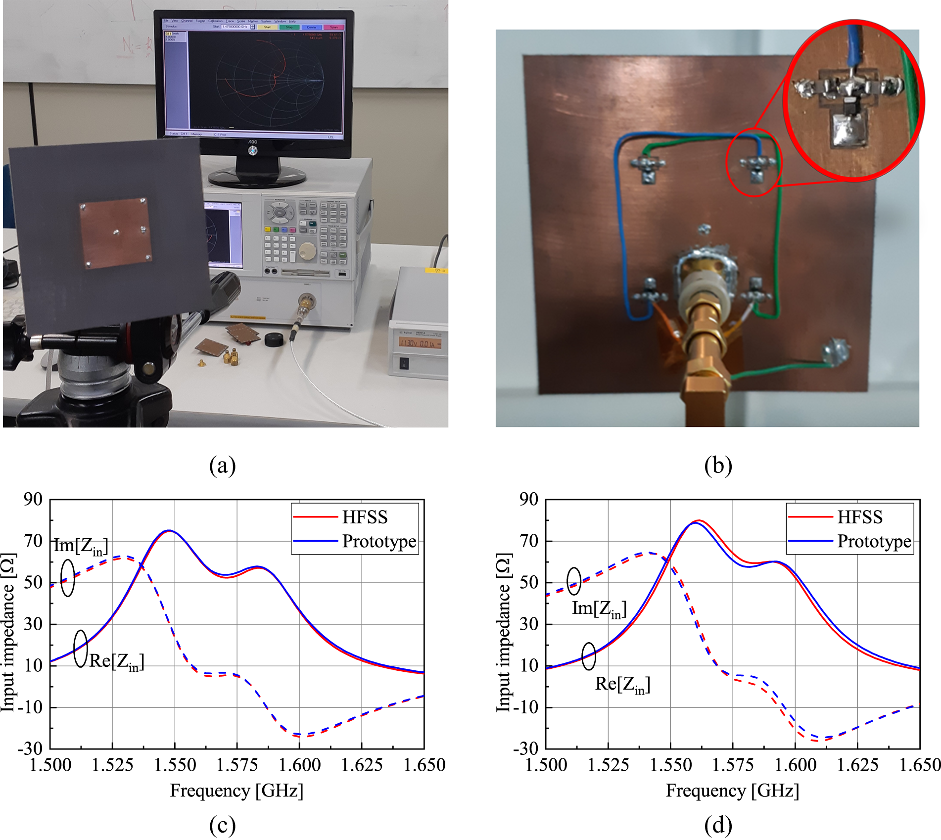
The antenna is printed on the same substrate as the previous designs, and its initial dimensions are derived from the cavity model: a = 37.25 mm, x 1 = 6.40 mm, and y 1 = a/2, with metallic vias of radius 0.5 mm. The varicap cathode is soldered onto a floating copper pad, which is connected to the ground plane through two 1000 pF decoupling capacitors, as illustrated in fig. 4. Consequently, for RF signals, the varicap cathode is directly connected to the ground through a low-reactance path, while it is isolated from the ground for DC voltages. Additionally, a shorting pin with a radius of 0.5 mm is placed at the center of the patch to allow the connection of the varicap anode to the ground for DC voltages. The varicap bias voltage is then applied between the floating copper pad and the ground. It is important to note that this shorting pin does not disturb the electric field distribution under the patch, as the field is null at the center position. A similar biasing solution was used in the reconfigurable filter presented in [Reference Sirci, Martínez, Taroncher and Boria29], which eliminates the need for an RF choke to isolate the DC source. Subsequently, the radiator dimensions and the positioning of the varicaps were optimized in HFSS to account for the bias elements introduced in the geometry, resulting in the following dimensions: a = 34.00 mm and x 1 = 3.00 mm.
Geometry of the reconfigurable antenna.

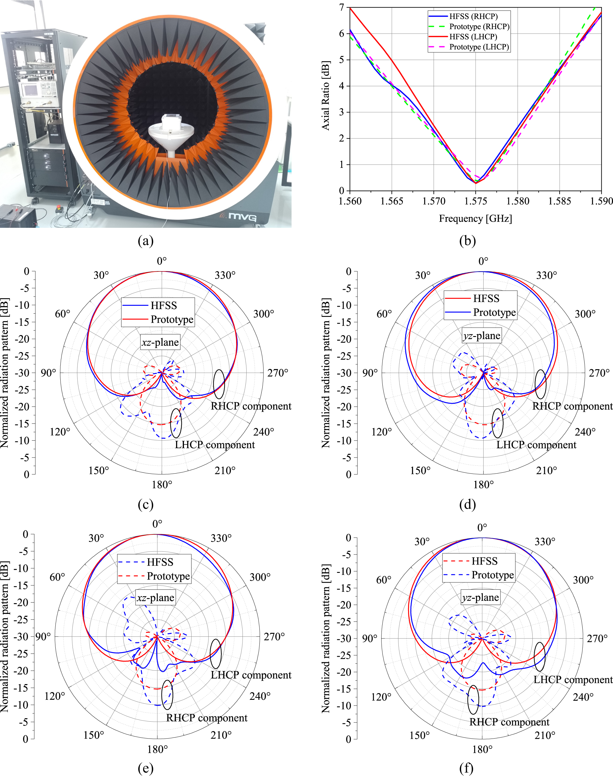
The front and back views of the antenna prototype, along with the input impedance measurement setup, are shown in fig. 5(a) and (b). By experimentally adjusting the bias voltages to V1 = 12.45 V and V2 = 11.45 V, the antenna operates in the RHCP state, while reversing these voltages produces the LHCP state. The measured input impedances for both RHCP and LHCP states are presented in fig. 5(c) and (d), respectively. The radiation patterns were measured using an MVG StarLab system, as depicted in fig. 6(a). The broadside AR versus frequency is illustrated in fig. 6(b), showing levels below 0.5 dB for both RHCP and LHCP states at 1.575 GHz. fig. 6(c) and (d) present the normalized radiation patterns for the RHCP state, including the co-pol and cross-pol components in the principal planes (xz and yz) at 1.575 GHz. Similarly, fig. 6(e) and (f) show the normalized radiation patterns for the LHCP state, highlighting the co-pol and cross-pol components. From these patterns, we note that the axial ratio remains below 6 dB throughout the entire upper region of all four plots. The excellent agreement between experimental and theoretical results validates the proposed model and confirms the effectiveness of the design strategy.
Prototype. (a) Front view and input impedance measurement setup. (b) Back view. (c) Input impedance (RHCP state). (d) Input impedance (LHCP state).

Prototype radiation patterns. (a) Measurement setup. (b) Broadside axial ratio. (c) xz-plane (RHCP state). (d) yz-plane (RHCP state). (e) xz-plane (LHCP state). (f) yz-plane (LHCP state).

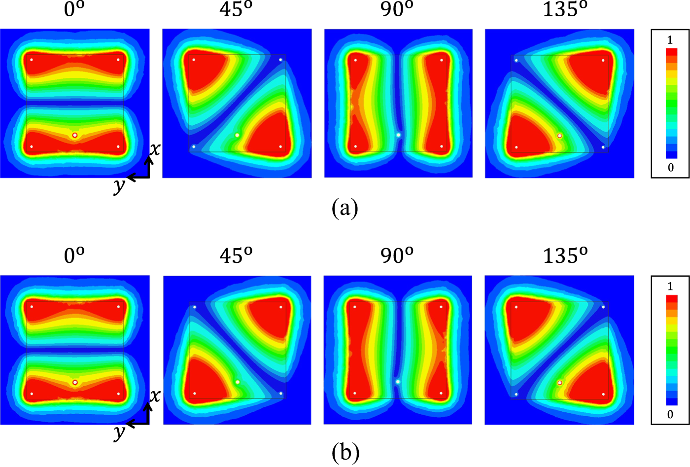
To clarify the principle of circular polarization reconfiguration, fig. 7 shows the magnitude of the electric field inside the dielectric substrate for both configurations mentioned. The analysis encompasses four consecutive excitation phases (0°, 45°, 90°, and 135°). fig. 7(a) demonstrates the anticlockwise field rotation (antenna top view), with the main beam propagating out of the page along the z-direction, leading to RHCP polarization. On the other hand, fig. 7(b) presents the field distribution for LHCP operation, showcasing the reverse rotation.
Normalized magnitude of the electric field within the dielectric substrate. (a) RHCP configuration. (b) LHCP configuration.

Before concluding this section, it is important to note that the bias voltages applied to the varicap diodes can be adjusted to tune the frequency of the minimum broadside axial ratio around 1.575 GHz. This feature allows the antenna to reconfigure its frequency for small ratios. Most polarization-reconfigurable antennas use p-i-n diodes to switch between polarization states [Reference Alhamad, Almajali and Mahmoud30], which often require complex circuitry to achieve frequency reconfiguration, even for small variations, or cannot incorporate frequency reconfiguration at all [Reference Al-Yasir, Abdullah, Parchin, Abd-Alhameed and Noras31, Reference Row and Hou32]. Therefore, the proposed antenna is well-suited for narrow band applications that need polarization reconfiguration between RHCP and LHCP states, as well as frequency tuning.
Conclusion
This letter introduces an improved analytical model for analyzing microstrip antennas loaded by metallic vias terminated with lumped loads. The proposed formulation addresses the procedure for computing the radiated fields, including all modes supported by the equivalent cavity. The model was applied to both CP and LP radiators, and the results compare well with those from HFSS. Additionally, a prototype of a polarization-reconfigurable antenna was designed based on the values obtained from the model. Only a slight adjustment in the bias voltages of the varicaps relative to the theoretical values was necessary to achieve a low-measured AR, demonstrating that the model is a powerful tool for predesign, in addition to offering valuable physical insights into the antenna operation. Furthermore, it can be readily extended to other microstrip antenna geometries, such as cylindrical, spherical, conical, and even circular patches.
Acknowledgement
This work was supported by the National Council for Scientific and Technological Development – CNPq – Brazil (Grants: 405889/2021-6 and 305944/2023-1).
Competing interest
None declared.

Fúlvio F. Oliveira received his B.S. degree in telecommunications engineering from the Instituto Nacional de Telecomunicações (INATEL), in 2006, and his M.S. degree in electronic engineering from the Aeronautics Institute of Technology (ITA), S. J. dos Campos, Brazil, in 2021. He is currently manager of the Weapon Systems of the Brazil’s Navy. His research interests include microwave engineering, electromagnetic theory, and antennas.

Juner M. Vieira received his B.S. in Telecommunications Engineering from the Federal University of Pampa in 2017, his M.S. in Electrical Engineering from the same institution in 2019, and his Ph.D. in Electronics Engineering focusing on microwave and antennas from the Aeronautics Institute of Technology in 2023. He is currently a Technological Development fellowships holder within the Space Electronics and Computing Division at INPE (Brazil). His research interests include microwave circuits, microstrip antennas, and antenna arrays.

Daniel B. Ferreira received the B.S. degree (summa cum laude) in electronics engineering and the M.S. and D.S. degrees in electronics and computer engineering from the Aeronautics Institute of Technology, Sao Jose dos Campos, Brazil, in 2009, 2011, and 2017, respectively. He is currently an Assistant Professor at the Department of Microwaves and Optoelectronics, Aeronautics Institute of Technology, Sao Jose dos Campos, Brazil, and a member of the Laboratory of Antennas and Propagation (LAP/ITA). His research work is mainly focused on microstrip antennas mounted on curved surfaces, frequency-independent antennas, and antenna arrays.

Daniel C. Nascimento received his B.S. degree in telecommunication engineering from the University of Taubaté, Taubaté, Brazil, in 2004, and the M.S. and Ph.D. degrees in electronic engineering from the Aeronautics Institute of Technology (ITA), São José dos Campos, Brazil, in 2007 and 2013, respectively. In 2009, he was appointed as an Assistant Professor with the Department of Electronic Engineering, ITA, where he has been an Associate Professor since 2021. He is currently the Head of the Laboratory of Antennas and Propagation, ITA. His research interests include the areas of microstrip antennas, phased arrays, and direction-finding systems.