Magnetic nano-/micro-materials have stimulated great interest not only for its fundamental scientific interest but also for its many technological applications. Among the magnetic materials, magnetite (Fe3O4) is especially intriguing because of its unique electrical and magnetic properties. In the past decade, there has been increasing attention and effort paid to the design and synthesis of Fe3O4 with controlled size and morphology. For the fabrication of tubular structure, in particular, different synthetic routes have been applied, such as template reactions,Reference Liu, Li, Fan, Zhu, Jiang, Ding, Hu and Huang1 rolling up layered materials,Reference Geng, Zhan, Jiang, Guo and Xing2 and hydrothermal methods.Reference Jia, Sun, Yan, You, Luo, Han, Pang, Zhang and Yan3 The template-based method to produce Fe3O4 or other metal oxide tubular structure is of prominence for its good control of dimension and surface morphology. The templates used range from metal oxide, like MgO,Reference Geng, Zhan, Jiang, Guo and Xing2 ZnO,Reference Jia, Sun, Yan, You, Luo, Han, Pang, Zhang and Yan3 and anodic aluminum oxide,Reference Wang, Geng, Wang, Ye and Tao4 to carbon nanotubes.Reference Sun, Yuan, Liu, Han and Zhang5 Compared with these inorganic template materials, using polymer as the template has its own merits, including the ease of fabrication, potential for large scale applications, economical cost, and low decomposition temperature.
Electrospinning is a facile and versatile route to produce exceptionally long polymer nano-/micro-scale fibers possessing uniform diameter and good composition control. Electrospun fibers as the template, defined as TUFT (tubes by fiber templates) by Greiner first,Reference Bognitzki, Hou, Ishaque, Frese, Hellwing, Schwarte, Schaper, Wendorff and Greiner6 have already been used satisfactorily to produce tubular structure for a wide range of materials, such as ZnO,Reference Choi, Ankoina, Youn, Oh, Hong, Rothschild and Kim7 TiO2,8 and Al2O3.9 However, this strategy has not yet been applied to the fabrication of Fe3O4 tubes.
Herein, we use the electrospun polystyrene (PS) fibers as the template to fabricate tubular structure of Fe3O4. Although the electrospun fibers have been applied as template in previous studies, their process normally uses techniques such as chemical vapor deposition or atomic layer deposition. These techniques not only make high demand on apparatus but also might cause certain pollution. Our work also offers a method taking advantage of electrostatic force and is simple, inexpensive, and nontoxic.
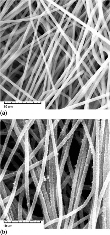
The initial substrate template constituted the matrix of electrospun PS fibers. Electrospinning condition was optimized by the adjustment of concentration of the solution, voltage applied, and the flow rate of the solution. In the electrospinning process, the PS fibers were overlaid to form a white membrane. Figure 1(a) is the scanning electron microscope (SEM) image of the as-electrospun PS membrane. The average diameter of the electrospun PS fibers was found to be 700 ± 50 nm. The morphology of the fibers is smooth and uniform without defects such as beads or rupture. The fibers were straight because a rotating drum was applied to help collect the fibers, and thus there was a dragging force during the collection.
SEM images of (a) as-electrospun PS membrane and (b) Fe3O4-coated electrospun fibers.

Electrostatic force was used to push forward the coating process in our work. Sulfonation was vital because metal cations cannot be anchored on the surface of pure PS fibers. Membranes after sulfonation were immersed in FeCl2 for absorption. Fe2+ was chosen to be the precursor, followed by oxidation to form crystalline particles and produce a Fe3O4 sheath deposited over the PS fiber mat. From the SEM image [Fig. 1(b)], it can be seen that the fibers have a coarse surface and become straight again because of the formation of the rigid sheath.
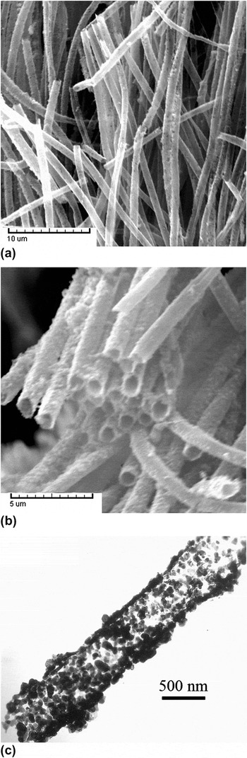
Calcination was applied for both the removal of the template materials and the further perfection of the Fe3O4 crystals. The SEM image of Fe3O4 tubes after calcination is shown in Fig. 2(a). The result confirms that tubes after calcination preserve the original morphology of the fiber template. The inner diameter of the tubes is about 600 ± 50 nm. Interestingly, the diameter of the hollow tubes decreases, compared with that before calcination. This reduction of diameter may be attributed to two main reasons. On the one hand, PS completely decomposed and disappeared gradually during calcination, leaving the core space vacant and the Fe3O4 and sheath composition shrunk accordingly. On the other hand, reorganization of Fe3O4 might happen at high temperature. This can also account for the formation of more smooth outer surfaces of the tubes during calcination. On the edge of the sample, there are many broken ends [Fig. 2(b)], indicating tubular structure of the product. Also, we can see from the broken ends that the formation of tubes is universal and the size distribution is uniform. To further explore the structure, transmission electron microscopy (TEM) image of the tubes is given in Fig. 2(c). It again suggests that the tubes are hollow instead of being solid wires or rods. The tube thickness is about 50 nm. Each tube is composed of numerous individual crystalline particles in the range of 30–50 nm or clusters of these nanoparticles.
SEM images of the (a) Fe3O4 tubes and (b) the broken ends of the tubes at high magnification; (c) TEM image of the microtube.

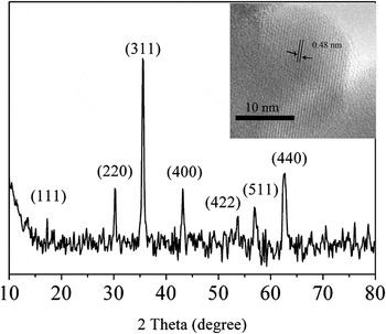
The crystal structures of Fe3O4 tube were confirmed by x-ray diffraction shown in Fig. 3. The characteristic peaks that occurred at 2θ of 17.2°, 30.1°, 35.5°, 43.2°, 53.5°, 56.8°, and 62.7° were all labeled by their corresponding reflection. The pattern matches well with the previous report (JCPDS No. 003-0863) and can be indexed as pure phase Fe3O4. No obvious impurity can be detected. The inset is the HRTEM image of the sample, which is also in agreement with the conclusion of XRD. Lattice fringe of 0.48 nm can be observed, which is believed to be the (111) lattice place of the Fe3O4 crystal.
X-ray diffraction (XRD) pattern of the Fe3O4 tubes. The inset is the high-resolution transmission electron microscope (HRTEM) image of the Fe3O4 tubes.

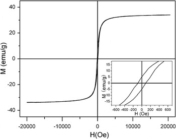
The magnetic hysteresis loop at room temperature for the obtained Fe3O4 hollow tubes is given in Fig. 4. The value of saturation magnetization (M s) of the tubular Fe3O4 particle assembly is 37 emu/g. Some reasons might be responsible for this relatively low M s value compared with that of bulk phase. It is known that coordination defects and disorder may exist for the magnetic molecules on a surface. This phenomenon may be especially significant for tubes in this case because they are actually assemblies of nanoparticles and, therefore, own extreme high surface-to-volume ratio. Also, the carbonized material, that is, the residue of polymer after calcination, may be one of the reasons. Carbonized materials exist in the final product, which may have strong interaction with the iron atoms at the particle surface. Besides that, a small quantity of weak magnetic oxides on the surface formed during the calcination also explains the decrease of M s as M s is a value proportional to the weight of the magnetic materials.
Magnetic hysteretic loop of the Fe3O4 microtubes.

In summary, tubular structure of Fe3O4 was fabricated with sulfonated electrospun PS fibers as the template. Thermal degradation was used to remove the template material. Fe3O4 microtubes are uniform and smooth and exhibit a ferromagnetic behavior. Fe3O4 tubes made in this way will expect the advantages inheriting from the electrospun template, such as long length and high aspect ratio. It can also form functional composite by embedding specific particles in their submicron-size interior. All these properties are especially important for magnetic materials because of their great potential in catalysis, fluidic sensing, and biological applications.
ACKNOWLEDGMENT
This work was supported by “Shu Guang” project (09SG02) supported by Shanghai Municipal Education Commission and Shanghai Education Development Foundation.
APPENDIX: MATERIALS AND METHODS
Polystyrene (PS) (M w = 280,000 g mol−1) was purchased from Secco Co. Ltd., China. FeCl2 was purchased from Aladdin (China). Cetyltrimethyl ammonium bromide (CTAB) was purchased from Shanghai Wenmin Biochemical Technology Co. Ltd. (China). The other reagents were purchased from Sinopharm Chemical Reagent Co. Ltd. (China). All the reagents were of analytical grade and used without further purification. PS was dissolved in N,N-dimethylformamide, and the concentration of the solution was fixed to be 15 wt%. 1 wt% CTAB was added to the solution. The electrospinning process was carried out with applied voltage of 20–25 kV and a feeding rate of about 0.5 mL/h. The as-prepared PS membranes were immersed in 98% sulfuric acid at 40 °C with vigorous stirring for 1 h to get sulfonated. Membranes were then immersed in FeCl2 (1 mol/L) solution under nitrogen gas for 1 h. NaOH (1 mol/L) solution was then added until the pH value was 10. Oxidation of Fe(OH)2 was initiated by passing air instead of nitrogen gas. KMnO4 (KMnO4/FeCl2 = 1/3 mol/mol) as oxidant was also added. After stirring at 85 °C for 1 h, the electrospun membranes were taken out from the mixture and rinsed with deionized water. To overcome the excess of Fe3O4, sonication was applied for 1 min. Then the membranes were dried for 1 day at room temperature. The polymer template was removed by calcination under nitrogen atmosphere at 500 °C for 3 h. Scanning electron microscope (Tescan) was performed at an acceleration voltage of 20 kV. Transmission electron microscopic (TEM) images were collected by an H-600 (Hitachi) transmission electron microscope under an acceleration voltage of 75 kV. High-resolution TEM observations of nanofibers were performed with a Philips CM 300 FEG TEM under an acceleration voltage of 200 kV. X-ray diffraction patterns of the samples were recorded using an X’Pro x-ray diffractometer with Cu Kα radiation (λ = 0.1548 nm). A vibrating-sample magnetometer (LDJ-9600) was used to study the magnetic properties of Fe3O4 particles.