I. INTRODUCTION
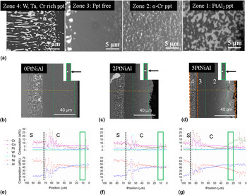
Diffusion aluminide bond coats are an example of compositionally and microstructurally graded coatings with significant variation in mechanical properties through depth. Reference Jaya, Jayaram and Biswas1 Although having a B2-(Pt,Ni)Al matrix throughout, the process of pack aluminizing during deposition of these coatings on Ni superalloy substrates and thermo-mechanical cycles during service leads to extensive inter-diffusion of elements between the substrate and the coating. This results in a gradient in chemistry, microstructure, and hence properties. Reference Das2 These substrate elements either get into the solid solution (e.g., Co, Ti) or precipitate out as complex intermetallics (e.g., constituting W, Ta, Cr) with varying morphologies and distributions through the coating depth. Pt is deliberately introduced since it is known to improve oxidation resistance of bond coats that form a part of thermal barrier coatings on gas turbines and aero-engine blades, Reference Gleeson, Wang, Hayashi and Sordelet3 and this is expected to alter the mechanical properties further. According to the distinct microstructural features of the high Al activity bond coat, four different zones can be clearly identified in the cross-section [Fig. 1(a)], details of which can be found elsewhere as well. Reference Jaya, Jayaram and Biswas1 Zone 1 consists of PtAl2 precipitates in a PtNiAl matrix, zone 2 consists of α-Cr precipitates in a PtNiAl matrix, zone 3 is a precipitate free zone of NiAl, and zone 4 consists of intermetallic precipitates rich in W, Ta, and other heavy elements from the substrate, in the NiAl matrix.
(a) Microstructure of a 5PtNiAl bond coat cross-section showing all the four zones appearing in a high activity diffusion aluminide coating. (b–d) Microstructure (SEM) and (e–g) composition (EPMA line scan) across the three bond coat samples (a) 0PtNiAl, (b) 2PtNiAl, and (c) 5PtNiAl. Zone 2 is highlighted using the dotted lines in green while the exact position of the microbeams within zone 2 is shown in solid box in green. Only those elements whose concentration is above 1 at.% are shown.

Since introduction of Pt into the bond coats was made due to empirical observations of improved adhesion of the alumina oxide scale to the bond coat, Reference Gleeson, Wang, Hayashi and Sordelet3 little attention has been devoted to the effect of its addition on the mechanical behavior of the bulk NiAl alloy in general and to the coating in particular. Reference Pan, Chen, Wright and Hemker4–Reference Alam, Kamat, Jayaram and Das8 The fracture behavior of NiAl is very sensitive to composition, microstructure, and processing conditions, Reference Miracle and Darolia9,Reference Noebe, Bowman and Nathal10 with both the fracture toughness and fracture mode showing transitions with increasing deviations from stoichiometry and alloying additions. Complex microstructures arising in the bond coat combined with observed size effects in fracture behavior require that samples be probed directly at the length scales of the coating rather than be extrapolated from known bulk NiAl behavior. Besides, these nonequilibrium structures that arise during the pack aluminizing process due to extensive inter-diffusion with the superalloy substrate cannot be emulated in bulk alloys produced in isolation. As-cast PtNiAl alloys have been produced by arc melting techniques but the process is expensive, especially to produce samples that comply with American Society for Testing and Materials (ASTM) standard sizes. Investigations dealing directly with the response of the stand-alone coatings to thermo-mechanical loads are limited in the literature due to the difficulties in isolating the coating, free from the constraints of the substrate. Pan et al. pioneered the use of micro-tensile tests of free-standing low activity bond coats, carrying out tests across a temperature range covering the brittle to ductile transition temperature (BDTT) of the sample. Reference Pan, Chen, Wright and Hemker4 In addition to quantitative determination of elastic modulus, yield strength, and plastic strain, microstructural evolution of these coatings during thermal cycling and creep was also a part of these studies. Alam et al. extended this work to high-activity bond coats of varying Pt concentration to study their tensile properties while also performing extensive transmission electron microscope (TEM) analysis to investigate the mechanisms of their deformation. Reference Alam, Kamat, Jayaram and Das8 They found that although Pt rich bond coats possess a higher strength due to solid solution strengthening, they also display a higher BDTT, suggesting that they continued to remain brittle over a larger temperature range. Therefore, the fracture behavior of Pt containing bond coats is of considerable interest.
Both Pan et al. Reference Pan, Chen, Wright and Hemker4 and Alam et al. Reference Alam, Kamat, Jayaram and Das8 treated the bond coat as one single unit, without considering the difference in the properties across the gradient region. Additional insight can be gained if differences between individual zones of the bond coat microstructure are taken into account. These can be accomplished using small-scale fracture mechanics experiments localized at specific microstructural features of interest as demonstrated by Iqbal et al. Reference Iqbal, Ast, Goeken and Durst11 and more recently, by Ast et al. Reference Ast, Przybilla, Maier, Durst and Goeken12 They used both linear elastic fracture mechanics (LEFM) and elastic-plastic fracture mechanics (EPFM) methods to determine the K IC of both soft and hard orientations of NiAl grains using micro-cantilever bend tests. They recorded significant anisotropy in fracture toughness between the two orientations and demonstrated the capability of such microscale tests to yield reliable fracture properties in semibrittle systems. A comparison between different fracture test methods by Jaya et al. Reference Jaya, Kirchlechner and Dehm13 on single crystalline Si has revealed that valid K IC data can be obtained independent of the test geometry. In a previous work on bond coats, Jaya et al. carried out clamped micro-beam bend tests on individual zones of the coating microstructure. Reference Jaya, Jayaram and Biswas1 They showed a rise in initiation fracture toughness (K IC) from 5 to 20 MPa·m1/2 with increasing Ni:Al ratio in the matrix. Similar changes in fracture toughness were shown from micro-cantilever bend tests on low activity bond coats as a function of NiAl matrix stoichiometry. Such differences between individual zones were discerned only because the test specimens came entirely from within a single zone. More importantly, the study by Jaya et al. Reference Jaya, Jayaram and Biswas1 revealed that zone 2 possessed the lowest K IC of ∼5.5 MPa·m1/2, making it susceptible to crack initiation and endangering the structural integrity of the bond coats when exposed to complex stress cycles during service. Hence, zone 2 was chosen for a case study of fracture behavior with changing Pt concentration. Pt has a maximum solid solubility of 25 at.% in B2-NiAl matrix Reference Gleeson, Wang, Hayashi and Sordelet3 and occupies the Ni sublattice. Reference Jiang, Besser, Sordelet and Gleeson14 It is to be noted that the heterogeneous nature of the bond coat makes it challenging to isolate the contribution of Pt alone to the fracture behavior. The inherent advantage of using zone 2 over zone 1 for these studies is that it is free from PtAl2 precipitates whose effect can overshadow that of Pt in solution. Zone 1 occurs only for bond coats with a higher Pt concentration (5PtNiAl and above). An additional advantage of probing zone 2 is that the microstructure of low activity bond coats throughout their cross-section resembles zone 2 of high activity bond coats and a direct comparison can be made between the two types of coating. It is also to be noted that the microstructural features of zone 2 in terms of precipitate type and morphology is similar for all three PtNiAl compositions. Therefore, the principal objectives of the present study were to determine fracture properties of zone 2 as a function of Pt content, and to develop a qualitative understanding of the toughening mechanisms at play.
II. EXPERIMENTAL METHODS
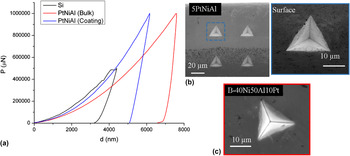
Three different pack aluminized high activity compositions containing 0, 2, and 5 μm thick layer of Pt during deposition were chosen for the study. They are designated as 0PtNiAl, 2PtNiAl, and 5PtNiAl, respectively [Figs. 1(b)–1(d)]. Note that the prefix number refers to the electrodeposited layer thickness of Pt and not to the concentration of Pt in the coating. The pack aluminizing procedure is described elsewhere in detail. Reference Alam, Kamat, Jayaram and Das8 All three samples were deposited on the superalloy CM-247-LC (composition in at.%: Ni, 9.1 Co, 8.1 Cr, 9.5 W, 5.6 Al, 3.2 Ta, 1.5 Hf, 0.7 Ti, 0.02 Zr, 0.5 Mo, 1.15 B, 0.07 C). Three arc melted bulk PtNiAl ternary alloys of the same nominal composition as that of zone 2 of the bond coats were also studied as reference samples. The bulk alloys were free from precipitates and other interdiffusing elements and their grain size was 3 orders of magnitude larger than those of the coatings. They are designated as B-50Ni50Al, B-45Ni50Al5Pt, and B-40Ni50Al10Pt. Electron probe microanalysis (EPMA) (JEOL, JXA-8530F, JEOL, Peabody, Massachusetts) was carried out for composition mapping across the cross-section of the three coatings as well as randomly selected regions of the three bulk alloys. X-ray diffraction (XRD) was used to determine their lattice parameters using the standard cos2θ/sinθ method. Reference Cullity15 Hardness and elastic modulus were determined using nanoindentation (TI-900, Hysitron Inc., Minneapolis, Minnesota) by applying the well-known Oliver–Pharr method. Reference Oliver and Pharr16 Cube corner indentations were carried out to determine possibility of indentation cracking in the coatings as well as in the bulk alloys (Fig. 2). While both the coating and bulk alloy were used for material characterization (composition, hardness, and modulus), fracture property measurements were carried out only across the coatings, since fracture behavior is very sensitive to the actual material microstructure which is very different in the two cases, and cannot be reproduced or replicated in bulk form.
(a) P–d curves of cube corner indentations carried out on Si (100) and PtNiAl in bulk and coating form. (b) Indentation impressions on the coating cross-section and magnified images of the indent on zone 2 of the 5PtNiAl coating showing no evidence of cracking or damage on the surface. (c) Indentation impression on the bulk PtNiAl alloy B-40Ni50Al10 Pt, showing no evidence of radial or lateral cracks.

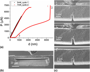
The clamped beam geometry in bending, Reference Jaya, Jayaram and Biswas1 which was found most suitable for achieving stable crack growth in bond coats previously, Reference Jaya and Jayaram17 was used in the present work as well. Focused ion beam (FIB; Strata 200xP, FEI Company, Hillsboro, Oregon) was used to micro-machine beams of 80 × 10 × 8 µm3 using 6000 pA for coarse cuts, 1000 pA for final polishing and 10 pA for notching of starter cracks. The position of the micro-beams with respect to the bond coat cross-section is shown in green in Fig. 1. A nominal starter crack length (a)/width (W) ratio of 0.3–0.4 was maintained in all cases. It has been shown by a number of studies on Si, W, and NiAl that FIB notches are as effective as actual precracks when the notch root radius is kept below 200 nm in micro-scale specimens. Reference Jaya, Kirchlechner and Dehm13 All the fracture tests were carried out inside an SEM (SIRION, FEG XL30, FEI Company, Hillsboro, Oregon) using an in situ nanomechanical instrument (Picoindenter PI85, Hysitron Inc., Minneapolis, Minnesota) with a wedge tip (120° apex angle) (Fig. 3). The specimens were loaded in 3-point bending mode aligning the tip axis with the notch. Loading was carried out in force control with a loading rate of 50 µN/s for fracture toughness measurements. In a separate experiment, a load-hold-load-hold sequence (with hold time of 10 s after every 1 mN load increment) was used for crack growth and R-curve studies. K IC was extracted as a function of crack length from the fracture loads corresponding to crack initiation and growth using extended finite element (XFEM) simulations, the details of which are given elsewhere. Reference Jaya and Jayaram17,Reference Jaya, Bhowmick, S Asif, Warren and Jayaram18 The R-curve measurements were carried out on 3 micro-beam samples each in zone 2 of the 2PtNiAl and 5PtNiAl samples. All the fracture toughness calculations were based on LEFM since deviations from linearity were not observed in the load–displacement curves before crack growth in any of the samples.
Snapshots from an in situ clamped beam fracture test on the zone 2 of a 5PtNiAl specimen showing (a) P–d curve, (b) the full length clamped beam geometry, and (c) magnified images of the crack tip as the specimen is loaded to fracture. (a) and (c) show the different stages of crack initiation and propagation in the specimen. The beam deformation is linear elastic (in the first cycle up to at 5 mN) and until the first pop-in at 6.5 mN, after which there is a drop in stiffness due to crack initiation, and further loading which eventually results in crack propagation throughout the entire specimen width at 7 mN.

III. RESULTS
The chosen Pt layer thicknesses in the present study result in a Pt concentration of 0, 5, and 14 at.% in the B2 (Pt,Ni)Al matrix of zone 2, respectively. Figure 1 shows the microstructure and composition across the cross-section of three such bond coat samples that were studied in the present work. Figure 1(e)–1(g) shows line scans of the concentration profiles of all the elements through the coating depth. The Pt content decreases sharply from the coating surface toward the coating–substrate interface, and is present only in measurable quantities in zones 1 and 2 of the bond coat. The Ni and Al concentrations vary more gradually across the cross-section. Although the superalloy composition is held constant in all the three cases, the concentration of other elements diffusing from the superalloy into the bond coat are influenced by the changing Pt content. In this respect, Pt indirectly determines the bond coat composition and associated property changes. In all the three cases, zone 2 contains all the Pt in solid solution in the B2 (Pt,Ni)Al matrix. A high volume fraction (above 35%) of spherical α-Cr precipitates are found throughout this zone with an average precipitate size of 350 nm. The volume fraction of these precipitates also varies substantially with Pt concentration, increasing from ∼35% for 0PtNiAl to ∼45% for 5PtNiAl while their morphology and distribution remains independent of the Pt content. It has also been observed that grain size varies considerably for the three compositions, with zone 2 of 5PtNiAl having a grain size of 1 µm and that of 0PtNiAl having a grain size of 2 µm, indicating that there is some influence of Pt in grain refinement. Table I gives relevant details of the composition, lattice parameter, indentation modulus, and hardness for three compositions along with their K IC. In view of the number of other elements present in the bond coat which either occupy the Ni or the Al sublattice, a comparison of the equivalent Ni:Al ratio is made instead of individual elements. The lattice parameter measured by XRD shows an increase with rising Pt content in the bond coat. This is expected since Pt is a larger atom substituting for Ni, resulting in lattice expansion. A similar increase in lattice parameter (from 2.869 nm for the binary stoichiometric alloy B-50Ni50Al to 2.926 nm for the B-40Ni50Al10Pt) was recorded for the bulk alloys with increasing Pt concentration. The local indentation modulus in zone 2 is seen to drop sharply from 270 GPa for 0PtNiAl to 180 GPa for 5PtNiAl (Table I). Hardness is seen to remain almost constant in the zone 2 at ∼6.5 GPa, within the standard deviation of the measurement for the 3 compositions. The hardness of bulk compositions is seen to be more sensitive to Pt concentration, showing a significant increase from 5.7 GPa for the B-50Ni50Al to 7.4 GPa for the B-40Ni50Al10Pt compositions. This indicates that while Pt does play a role in strengthening of the NiAl matrix, the influence of the large volume fraction of precipitates in the more complex microstructure of the bond coat is more significant in determining the hardness of the coating.
Composition in terms of equivalent (Ni + Pt + Co):(Al + Ti) ratio, corresponding Pt:Ni ratio, lattice parameter from XRD (a), elastic modulus (E) and hardness (H) from nanoindentation, K IC as measured from micro beam bending and corresponding plastic zone size and fracture energy G, calculated for zone 2 of the three PtNiAl compositions studied. The error bars represent the standard deviation from the average values.

Preliminary investigations on the fracture resistance of the bond coats were carried out using cube corner indentations along their cross-sections. Sharp indentations are known to cause radial and/or lateral cracking in brittle coatings. Reference Anstis, Chantikul, Lawn and Marshall19 Figure 2 shows a representative indent on the zone 2 of a 5PtNiAl composition along with the P-d curve in comparison to that of a bulk B-40Ni50Al10Pt alloy and a brittle Si (100). While the contour of the P-d curve of Si (100) is peppered with pop-ins (displacement jumps), those of PtNiAl in both the bulk and coating form show smooth contours. No evidence of cracking or damage is seen from either the surface or cross-section of the indents, suggesting that these coatings are not prone to elastic brittle fracture, unlike Si.
A typical load (P)-displacement (d) curve from a clamped beam bending experiment on the bond coat sample is shown in Fig. 3. The curves were seen to be linear, elastic until the first pop-in, which corresponded to crack initiation from the notch tip. The increased compliance of the beam was reflected in the reduced slope of the P–d curve on further loading/reloading of the sample. Cracks were seen to grow stably, resulting in gradual decrease in the slope or multiple pop-ins in the P–d curve. Fracture toughness was calculated using XFEM simulations (ABAQUS 10.2) in the absence of analytical formulations for the clamped beam geometry. The elastic properties (E, ν) of the sample as well as the maximum stress to failure (σf = H/3) were used as input to calculate the stress intensity factor (K I) as a function of load for each specimen separately. The K I corresponding to the fracture load (from the first pop-in in the P–d curve of the experiment) was used as the K IC. For the R-curve determination, XFEM simulations of the same clamped beam with increasing crack lengths were carried out. The crack lengths as measured from the in situ snapshots were used as inputs in the simulation. Again, the pop-in loads from the experiment were used to read out the new K I, which was termed the crack propagation toughness (K R). The impact of different experimental variables like notch root radius, FIB damage, and clamped boundary conditions on the fracture toughness measurement in the clamped beam geometry have been discussed elsewhere Reference Jaya, Bhowmick, S Asif, Warren and Jayaram18 and are not repeated here.
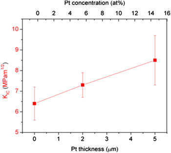
Figure 4 shows the K IC for the three compositions, reported as an average of 8 micro-beams tested in zone 2 of each composition. A clear rise in initiation K IC from 6.4 to 8.5 MPa·m1/2 with increasing Pt layer thickness can be seen. Error bars in Fig. 4 indicate standard deviation from the average value. Independent measurements using the same testing technique have been made in the literature on other more ‘homogeneous’ systems like single crystal Si Reference Jaya, Kirchlechner and Dehm13 and single crystal NiAl, Reference Jaya and Jayaram17 where the scatter is considerably lower (less than 0.2 MPa·m1/2). Experimental errors can occur with respect to measurement of beam dimensions, finite notch root radius, and misalignment of the indenter with respect to the notch; and these details are discussed in previous papers. Reference Jaya, Kirchlechner and Dehm13,Reference Jaya and Jayaram17,Reference Jaya, Bhowmick, S Asif, Warren and Jayaram18 Therefore, we attribute the higher standard deviation seen here to the heterogeneous microstructure of the bond coat matrix. The crack front encounters a fluctuating Ni:Al (equivalent) ratio, poly-crystallinity and changing grain orientation of the (Pt,Ni)Al matrix and associated anisotropy, as well as wide distribution of α-Cr precipitates, all of which add to the scatter. The crack tip therefore cannot encounter a constant, uniform process zone throughout the crack front. Such microstructural effects are absent in the single crystalline Si results, for example. Also, in comparison to bulk stoichiometric binary NiAl with a recorded K IC of ∼4 MPa·m1/2 (Ref. Reference Cullity15), the bond coat systems showed a higher K IC. Table I shows the corresponding Ni:Al and Pt:Ni ratio as well as the plastic zone size in each of them. Since Pt occupies the Ni sublattice in NiAl, this result could be an extension of the previous observations that among the off-stoichiometric nickel aluminides, the Ni rich NiAl possess a higher fracture toughness. Since the plastic zone size is 1/10th of the specimen width, these K IC values obtained are assumed to be valid plane strain fracture toughness results. This is despite the fact that the beam dimensions in small-scale tests cannot satisfy ASTM standards exactly, unlike mesoscale or macroscale tests. The crack trajectories do not show any significant differences in the three cases. The trajectories mainly exhibit microscopic kinks while propagating in macroscopic mode I (Fig. 5). Table I also shows the fracture energy (G) of the three bond coat systems calculated using Eq. (1). The enhanced fracture energy in Pt containing bond coats clearly points to additional dissipation mechanisms at the crack tip.
 $$G = {{K_{{\rm{IC}}}^2} \over E}\quad .$$
K IC of the three bond coat samples tested, as a function of Pt content, in terms of layer thickness during deposition and the resulting concentration in zone 2. The error bars indicate standard deviation.

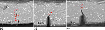
Typical crack trajectories of (a) unnotched and (b–c) notched clamped microbeam bend specimen in zone 2 of 5PtNiAl, showing crack kinking and bridging as the operating toughening mechanisms leading to crack arrest. The boxes in red show the points of crack arrest and bridging at precipitate particles.

It can also be observed from Figs 3 and 5 that none of the micro-beams fractured catastrophically and instead arrested before reinitiating at higher loads. Hence, the R-curve behavior of these coatings was studied by monitoring crack lengths at every stage of the stable crack growth with increasing load. Reference Jaya and Jayaram17 A dramatic increase in fracture toughness with crack length (by a factor of 2 or more) was seen in these specimens with an increase in crack length (Δa) of 2.5 μm, independent of their Pt concentrations. Table II shows the estimated K R values as a function of crack length. Cracks exceeding an a/W ratio of 0.8 are not considered for K R calculations since the stress fields of such cracks interact with the compressive stress field of the indenter and are also prone to free surface effects. Figure 5 shows crack trajectories in specimens as imaged after the tests are complete from both un-notched and notched beams. The crack trajectories indicate that the principal crack wake toughening mechanisms are crack kinking and bridging due to the precipitate particles.
R-curve behavior of 2PtNiAl (80 × 8 × 6 µm3) and 5PtNiAl (80 × 8 × 5.2 µm3) microbeam samples in terms of fracture loads (P f), K IC and corresponding crack lengths. Rising fracture toughness seen with increasing crack length.

IV. DISCUSSION
The micro-scale clamped beam fracture tests on the three bond coat compositions with increasing amounts of Pt show a clear rise in the K IC of zone 2 of the bond coat comprising of the B2 matrix and α-Cr precipitates. The elastic modulus is seen to drop correspondingly, exhibiting an increasingly elastically softer matrix. In addition, the bond coats show stable crack growth and an R-curve behavior independent of their Pt concentration, which has not been observed before. Plausible reasons for this enhancement in fracture toughness and increasing resistance to crack growth are discussed in the following paragraphs.
A. Defect chemistry and dislocation mechanism in binary B2-NiAl
Although considered nominally brittle due to the limited number of slip systems available in the B2 structure and high anti-phase boundary (APB) energy, Reference Miracle and Darolia9,Reference Noebe, Bowman and Nathal10 there is sufficient evidence for dislocation plasticity in favourably oriented binary NiAl. Reference Baither, Ernst, Wagner, Rühle, Bartsch and Messerschmidt20 As a function of composition, fracture toughness of Ni rich NiAl is known to be higher than Al rich NiAl in both bulk NiAl and bond coat systems due to the asymmetric defect types that form on deviating from stoichiometry. Reference Jaya, Jayaram and Biswas1,Reference Riethmüller, Dehm, Affeldt and Arzt5,Reference Noebe, Bowman and Nathal10,Reference Webler, Krottenthaler, Neumeier, Durst and Göken21 NiAl possesses a strong directionality in its bond and is a highly ordered covalent structure with some metallic character. Reference Fox and Tabbernor22 Al is a much bigger atom and is more electropositive. Hence, strong Al–Al repulsions exist while Ni–Ni nearest neighbors are preferred due to their increased contribution to the metallic character of the bond. Hence Ni rich NiAl possesses Ni antisites in the Al sublattice (NiAl) to accommodate off-stoichiometry, while Al rich NiAl contains constitutional vacancies in the Ni sublattice (VNi). Vacancies bring about hardening and accompanying brittleness in the Al rich NiAl since they are stronger obstacles to dislocation motion than antisite defects. Reference Ternes, Xie and Farkas23 B2-NiAl being a highly ordered system, the percentage of constitutional defects forming in its off-stoichiometric compositions is significant. Kogachi et al., Reference Kogachi, Tanahashi, Shirai and Yamaguchi24 reported 8–10% vacancy concentration of the type VNi for NiAl with 54 at.% Al and 5% antisite defects of the type NiAl for NiAl with 48 at.% Al. From their fracture strain calculations of three point bend experiments of pack aluminized and vapor deposited coatings, Reithmueller et al. Reference Riethmüller, Dehm, Affeldt and Arzt5 attribute the increase in fracture toughness of vapor deposited coatings to the decrease in Al content in the matrix. In the present case, a ternary alloying addition complicates the matter even further.
B. Effect of ternary Pt addition on the defect chemistry of B2 (Pt,Ni)Al
It is well established that Pt occupies the Ni sublattice in the B2 structure. Increasing Pt content results in increased antisite defects for hypo-stoichiometric NiAl (with less than 50 at.% Al) and reduced vacancy defects for the hyper-stoichiometric case. Reference Jiang, Sordelet and Gleeson25 Pt–Al has a negative interaction parameter and is a much stronger chemical bond compared to Ni–Al. Reference Feng, Xiao, Chen, Dua, Yua and Zhou26 Hence Pt is known to reduce the chemical activity of Al. More importantly, Pt is expected to enhance the metallic bond nature of the B2 structure, being more electronegative in character than both Ni and Al. Reference Tian, Han, Wei, Zheng, Jin, Sun and Hu27 In the present study, the off-stoichiometry varies from 52.6 to 43 at.% Al (equivalent) in the β-matrix for the three compositions with increasing Pt concentration (Table I), but in addition brings about PtNi defects. Accordingly, the 0PtNiAl is hyper-stoichiometric (>50% Al) and consists of constitutional vacancies as dominant defects while the 2PtNiAl and 5PtNiAl are hypo-stoichiometric (<50% Al) and consist of antisites (of varying concentration) as principal defects. These changes in defect structure and concentration in addition to the possibility of triple defect configurations and resulting changes in bond structure can be held primarily responsible for the observed difference in fracture toughness.
C. Effect of Pt on the mechanical behavior of the bond coat
While the indentation modulus shows a clear reduction with Pt addition, the hardness remains almost constant. While the modulus is a measure of the elastic properties of the matrix, the hardness reflects the microstructure more comprehensively. In this context, the two effects are separately discussed.
The effect of Pt on the elastic behavior of (Pt,Ni)Al should be seen in the light of elastic and shear modulus calculations as a function of defect chemistry. A drop in indentation modulus is seen with increasing Pt in the current study (Table I). Alam et al. also found a decrease in elastic modulus with increasing Pt content from tensile tests of free-standing coatings. Reference Alam, Kamat, Jayaram and Das8 From a combination of first principles calculations and ultrasonic wave velocity measurements of elastic constants on polycrystalline PtNiAl alloys, Jiang et al. Reference Jiang, Sordelet and Gleeson25 found that for a constant Al content x Al, Pt addition increases the bulk modulus but decreases the shear modulus of NiAl. A decrease in the ratio of shear modulus to bulk modulus is expected to cause an increased resistance to crack propagation in tension while promoting shear instead. Reference Feng, Xiao, Chen, Dua, Yua and Zhou26 While Pt does not change the constitutional point defect type in either Ni rich (NiAl) or Al rich (VNi) NiAl, its substitution into the Ni sublattice (PtNi) brings about significant changes in the defect concentration.
Next, the possible reasons for not seeing any perceptible change in hardness with Pt addition in the bond coat are discussed (Table I). Pt addition in the bulk alloys (from 0 to 10 at.%) with a constant Al concentration (50 at.%) results in a significant increase from 5.7 to 7.4 GPa, clearly demonstrating the role of solid solution strengthening due to Pt. Since Pt occupies the Ni sublattice to create PtNi defects, increasing the Pt concentration is expected to increase the dislocation-point defect interaction in comparison to the binary stoichiometric alloy. The fact that no such difference in hardness is seen across the bond coat of varying Pt concentration can be attributed to the off stoichiometry in the bond coat matrix. Due to inter-diffusion with the substrate, the Al concentration is neither a constant in the bond coat, nor is the alloy stoichiometric, unlike the bulk alloy. An increase in concentration of PtNi defects brings about a reduction in VNi defects in such a case. Therefore, the solid solution strengthening due to Pt is compensated by reduction in vacancy hardening due to which the hardness of the bond coat remains constant.
There could be an interplay of several other factors of the microstructure which Pt can influence, for the observed rise in fracture stress (in the brittle regime) or yield stress (in the ductile regime) of the bond coat in tension. Reference Alam, Kamat, Jayaram and Das8 Pt alters the defect chemistry and the resulting interaction of point defects with the dislocations. This influences both the friction stress and dislocation mobility. Pt also refines the grain size and therefore influences the Hall–Petch strengthening mechanism. It brings about increased rejection of α-Cr precipitates in the bond coat, influencing the precipitation strengthening mechanism as well. All these factors add up incrementally. Although individual contributions are difficult to separate out, Alam et al. Reference Alam, Kamat, Jayaram and Das8 did a thorough quantitative analysis of these factors and concluded that Pt directly impacts both the elastic modulus and grain size of the microstructure, resulting in a higher fracture/yield stress and fracture energy. Solid solution strengthening depends on the distortion produced in the lattice by the solute atom, which is a function of both the size and elastic property mismatch between the solute and the solvent atom, while its concentration in the matrix decides the magnitude of the effect. Reference Dieter28 Since Pt is substituting for Ni, the two atoms are compared here, leaving out Al from the discussion. The atomic radius of Pt is 12% larger than Ni (177 pm vs 149 pm), and hence PtNi can increase the barrier stress for dislocation motion owing to its size mismatch. But Pt also has a 20% lower shear modulus compared to Ni (61 GPa vs 76 GPa) 29 and its addition is known to reduce the local shear modulus of NiAl Reference Webler, Krottenthaler, Neumeier, Durst and Göken21 which can partly counter the effect. Jiang et al. Reference Jiang, Sordelet and Gleeson25 observed that the shear modulus decreased due to Pt addition, indicating that its indirect effect in changing defect concentration dominates over its direct effect of solid solution strengthening. The change in grain size with Pt addition was attributed to the imposition of drag forces by the PtNi and VNi defects on the grain boundary mobility of the B2 matrix during its formation. Reference Alam, Kamat, Jayaram and Das8 Strengthening due to grain refinement by Pt addition is expected to play a minor role (in the Hall–Petch scheme) since grain size variation is within a factor of 2. In addition there are other solute elements like Co, Cr, and Ti diffusing from the superalloy substrate whose contributions are impossible to separate out in the case of the three bond coat systems chosen. Alam et al. Reference Alam, Kamat, Jayaram and Das8 assume the contribution of other solute elements and the resulting precipitates to be constant for all the bond coat systems of their study since the substrate composition in all the cases are similar. But the solubility of these substrate elements diffusing into the coating will be affected owing to the Pt going in as a solute atom into the B2 matrix. The influence of the large volume fraction of precipitates, which are absent in bulk alloys, overshadows the contribution of point defects in strengthening/toughening the bond coat microstructure. This is discussed further in Section E.
D. Effect of Pt on the K IC of the bond coat
A possible explanation of the fact that Pt rich PtNiAl bond coats possess a higher fracture toughness despite a higher BDTT as reported earlier Reference Alam, Kamat, Jayaram and Das8 and a lower elastic modulus, hinges on the defect chemistry and bond energy changes that result due to Pt replacing the Ni in its sub-lattice (Section B). With Pt occupying the Ni sublattice, its effect on fracture toughness is expected to be similar to Ni rich NiAl. Surface segregation studies and density function calculations show that Pt–Al bonds are stronger than the Pt–Ni and Ni–Ni bonds and that Pt enhances the surface energy of B2-NiAl (110) from 1.8 to 2.4 J/m2 (Ref. Reference Yu and Hou30). This reinforces the idea that a Pt rich bond coat should inherently possess a higher work of failure (G) (Table I). This enhancement in fracture energy seems to overshadow the reduced elastic stiffness of the Pt based bond coats and thus result in a higher K IC, as measured in the present work. Tension tests on free-standing bond coats of varying Pt concentrations have shown that linear elastic behavior is followed by fracture at a stress which increases by 20 and 67%, respectively, in samples corresponding to 5 Pt and 10 Pt. Reference Alam, Kamat, Jayaram and Das8 Alam et al. attributed the enhancement in fracture stress to the local enhancement in the defect–dislocation interaction around PtNi defects, whose modulus is lower than the B2 NiAl matrix. This compares well with the ∼30% increase from 0 Pt to 5 Pt in initiation toughness seen in the present work.
E. Effect of Pt on the crack propagation toughness (R-curve) of the bond coat
R-curve behavior at micron-length scales was a distinct feature observed in these clamped beam fracture tests, irrespective of the Pt concentration (Table II). It is to be noted that the R-curve captured here is at the initial stages of crack growth, before reaching a steady state plateau value. While micro-scale tests enable the observation of the initial few microns of crack growth, which is typically ignored in macro-scale tests, the flipside is there is inadequate sample thickness to reach steady state before free surface effects and the compressive stress field of the indenter begin to influence crack growth. An expanding process zone at such length scales will encounter the free surface due to the limitations imposed by the external specimen dimensions, preventing a fully developed process zone from taking shape. Possibilities of size effects influencing such observed R-curve behavior in small-scale fracture mechanics samples have been discussed in a previous work. Reference Jaya, Bhowmick, S Asif, Warren and Jayaram18 The R-curve behavior in bond coats can be summarized as a combination of crack front mechanism of crack deflection and crack wake mechanism of bridging, both delivered due to the presence of α-Cr precipitate particles along the crack path. While the volume fraction of these particles does increase with increased Pt concentration, the impact of this on the R-curve behavior could not be assessed since the micro-scale samples were not sufficiently large enough for plateau values of fracture toughness to be reached. Cotton et al. Reference Cotton, Noebe and Kaufman31 found that Cr precipitated out as α-Cr when its concentration exceeded 1 at.% in the B2-NiAl matrix whereas Han Reference Han32 estimated a solubility up to 8 at.%. In this study, the Cr content in zone 2 was found to fluctuate from 3 to 6 at.%. The precipitates were all less than 1 μm in diameter, and found to share a coherent or semicoherent interface with the NiAl matrix, which is the case with the samples in this study as well.
1. Crack front
Micro-kinks that are ignored as aberrations in conventional macro-scale scheme of fracture testing lead to considerable variations in fracture toughness due to the changes they bring to the fracture mode, taking it from pure mode I to a mixed mode fracture. Cracks are seen to deflect along large kink angles (as high as 70°) in the tested regions (Fig. 5), and their effects get amplified at the micron-scale. A 60° kink from the mode I path can result in a 33% rise in fracture toughness. Reference Suresh33 Wiederhorn Reference Wiederhorn34 has shown that the fracture energy can rise by 2–3 times for crack bowing between penetrable particles while it can increase by 10 times for bowing around impenetrable ones. Interestingly, none of the particles in Cotton et al.’s work sheared during deformation, as seen from their TEM images, and the dislocation loops surrounding them suggested Orowan looping mechanism to operate for the dislocations to by-pass these particles. Reference Cotton, Noebe and Kaufman31 The volume fraction of α-Cr precipitates exceeded 35% in all 3 cases. The elasto-plastic mismatch between the α-Cr precipitates and the B2-PtNiAl matrix can be expected to result in localized residual stresses which will cause the crack to kink away from the particles [Figs. 5(b)–5(c)]. Though the magnitude of such stresses was not measured, there is sufficient evidence in the crack trajectory to show that crack kinking and bowing is one of the toughening mechanisms in operation.
2. Crack wake
Crack closure upon unloading without a visible trail of the crack path Reference Jaya, Bhowmick, S Asif, Warren and Jayaram18 is evidence for crack wake toughening in a semibrittle matrix material like NiAl. Crack closure occurs because the crack opening displacement (COD) is not sufficiently large to overcome the closure stresses imposed by the bridging precipitate particles. Un-notched beams bent to fracture in zone 2 [Fig. 5(a)] showed clear features of crack face bridging. A discontinuous crack trajectory was seen at the surface with the initial crack pinned at a precipitate particle and re-nucleating at some point ahead of the original crack tip. There was no evidence of particles shearing due to the crack, while their interface with the matrix fractured after a certain critical stress was reached. Bridging results in the nonplanar crack front seen in Fig. 5. The toughening due to particle bridging in the crack wake is sustained only up to a critical COD after which a plateau value is reached in the R-curve. This critical COD was not reached owing to the small specimen size used in the present study.
A systematic study of R-curve as a function of Pt concentration (and as a result, of the volume fraction of the α-Cr precipitates) is beyond the scope of the present work. From the limited number of experiments, a significant jump in fracture resistance can be seen in all the samples independent of their Pt content but none of them reached their saturation value. It is clear that the precipitate fraction happens to be higher in the coatings which have a higher Pt content (35% for 0PtNiAl compared to 45% for 5PtNiAl). The diffusivity of Cr into the bond coat is bound to be altered due to the Pt activity although the substrate composition is the same for all the three cases. The higher Pt concentration in the solid solution of the bond coat matrix therefore must have led to increased rejection of Cr as precipitates. From the discussion above, it is clear that these particles act as crack deflectors as well as bridging agents, and hence a higher volume fraction can be inferred to result in a higher plateau value of fracture toughness. It is more complicated to estimate the impact of a varying grain size on the crack resistance mechanism in bond coats. Rigney et al. Reference Rigney and Lewandowski35 found a grain size independent fracture toughness of 5 MPa·m1/2 for an NiAl alloy with 45 at.% Al. The effect of grain size on fracture toughness always hinges on the relative magnitude of grain and flaw size, as well as whether the fracture proceeds as inter-granular or trans-granular. Thus there is not much clarity in the literature regarding this issue.
Therefore, one can conclude that Pt influences the mechanical behavior of the bond coat, both directly on the strength of the B2 phase as well as indirectly through its effect on the precipitate fraction. Future work would require J-integral measurements or energy based calculations to capture all the crack resistance mechanisms operating in such complex heterogeneous materials. Such measurements will be important to facilitate optimization of the bond coat alloy chemistry for improved fracture resistance in addition to providing oxidation resistance to the superalloy blade.
V. CONCLUSION
Micro-mechanical fracture tests were carried out on bond coats with different Pt layer thicknesses and the results correlated to the composition and microstructure of the coating. Within a given zone, the initiation K IC was found to improve by 30% when the initial Pt layer thickness was increased from 0 to 5 µm. A simultaneous increase in Pt concentration in the NiAl matrix by 14 at.% and associated microstructural changes in precipitate volume fraction and distribution, as well as grain size points to the role of Pt in enhancing the fracture toughness of the bond coat. In addition to the obvious microstructural changes, Pt also alters the bonding and point defect character of the B2 matrix. Lower elastic stiffness, changed defect type and concentration and enhanced metallic bond character due to presence of Pt may have contributed to the higher K IC in Pt rich bond coats. A distinct R-curve behavior within a few micrometers of crack extension was also seen in all bond coat samples, independent of the Pt concentration. Evidence of crack kinking and precipitate bridging in the crack tip process zone was found from in situ observations of crack growth, leading to a rise in the resistance to fracture. Establishing the responsible mechanisms for enhanced fracture resistance forms the basis for exploration of cheaper alloying additions which can make similar changes to the defect and micro-structure.
ACKNOWLEDGMENTS
The authors thank Dr D.K. Das and Dr Md. Z. Alam of the Defense Metallurgical Research Laboratories, Hyderabad, India for providing the bond coat samples. B.N. Jaya and V. Jayaram thank the Defense Research & Development Organization, India for funding this project.