I. INTRODUCTION
Cell adhesion to biomaterials is a desirable process in many tissue engineering applications to regenerate nonfunctional or damaged tissues or organs.Reference Shastri and Lendlein1,Reference Jung, Wischke and Lendlein2 The application of tissue engineering principles in regenerative medicine enables the formation of 3D scaffolds based on polymer fiber materials similar to the structure of native extracellular matrix (ECM). Since the scaffold acts as an artificial ECM, it should mimic certain functions of natural ECM to facilitate cell adhesion, proliferation, differentiation, and formation of functional tissue.Reference Shastri and Lendlein3 A high surface-to-volume ratio and porosity of the fibrous scaffold are thought to enhance adhesion and colonization of cells within the matrix and support an efficient exchange of nutrients and products of metabolism within the matrix and with the environment.Reference Ma and Langer4,Reference Sundararaghavan and Burdick5 Material design of scaffolds is one of the key technologies for tissue engineering in terms of chemical composition and physical structure. Poly(etherimide) (PEI) has become a good candidate for wide range of biomaterial applications especially for extra corporeal systems such as oxygenators.Reference Kawakami, Mori, Takagi, Nagaoka, Kanamori, Shinbo and Kubota6–Reference Lange, Luetzow, Neffe and Lendlein11 The investigations on its biocompatibility have shown that polyimides do not exert any significant level of cytotoxicity or hemolysis and allow the attachment and growth of cells.Reference Hiebl, Lutzow, Lange, Jung, Seifert, Klein, Weigel, Kratz and Lendlein12–Reference Schneider, Kohl, Sauter, Becker, Kratz, Schossig, Jung, Lendlein, Ertel and Schulze-Tanzil14 PEI also possesses considerable mechanical strength and thermal stability,Reference Seifert, Mihanetzis, Groth, Albrecht, Richau, Missirlis, Paul and von Sengbusch10 which makes PEI suitable for steam sterilization. Furthermore, PEI has very good membrane-forming propertiesReference Seifert, Mihanetzis, Groth, Albrecht, Richau, Missirlis, Paul and von Sengbusch10 and can be chemically functionalized to modify surface properties or to link bioactive molecules. In this way, the resulting polymer material easily can be adapted to a specific application such as contact with blood or tissue cells.Reference Braune, Lange, Richau, Luetzow, Weigel, Jung and Lendlein15–Reference Tzoneva, Seifert, Albrecht, Richau, Groth and Lendlein17
Electrospinning is a well-established process, by which ultrafine fibers at the very upper limit of the fiber diameter range of natural ECM (upper nanometer to lower micrometer range) are produced using electrically charged droplets of melt polymer or their solution.Reference Reneker and Chun18 One promising approach to mimic the structure of native ECM and to support the cell growth is an inclusion of adhesive proteins in the scaffold design. For instance, fibronectin (FN)- and collagen (Col)-modified poly[(L-lactide)-co-(ε-caprolactone)] (PLLC) can more effectively support the growth of smooth muscle cells and epithelial cells than unmodified PLLC.Reference Zhu, Chian, Chan-Park, Mhaisalkar and Ratner19 To ensure endothelization of poly(acrylic acid)-grafted polyethylene films, Taguchi et al.Reference Taguchi, Kishida, Akashi and Maruyama20 used FN and Col immobilized on film surfaces. Cells behaved in a different manner in 2D and 3D environment.Reference Dubiel, Martin and Vermette21 In a 3D system, the adhesive ligands are spatially distributed in all geometric planes. Thus, all areas of the cellular organism are equally exposed to adhesive ligands. In that way, the formation of cell-matrix adhesive structures differ in 2D and 3D environmentReference Cukierman, Pankov, Stevens and Yamada22 and determine different cell characteristics as cell shape, cell adhesion, and cell motility. For example, human fibroblasts grown in collagen matrices produce a dendritic network of extensions but not fibroblasts on collagen-coated coverslips.Reference Grinnell23 Differences in mechanical properties, e.g., the elasticity of the 2D or 3D matrix, influence the cell behavior. Changes in the flux of metabolites and gases in 3D systems, compared with 2D, also greatly contribute to cell response.Reference Georges and Janmey24
Biological systems usually respond to applied electric field (EF). It has been shown that the application of EF can influence the quantity and the spatial orientation/conformation of adsorbed proteins on solid surfaces.Reference Morrow, McKenzie, Bilek, MacDonald, Stindt, Anetsberger and Martin25 Those changes in protein organization can alter their biofunctionality.Reference Song, Li, Yang and Xia26 Low (in strength and frequency) alternating current (AC) EF can induce a redistribution of cell surface receptors and a reorganization of the microfilament structureReference Cho, Thatte, Lee and Golan27,Reference Cho, Thatte, Lee and Golan28 as both processes are linked. The mechanism of action of AC electrical fields is most probably induced by elevated [Ca 2+], which in turn activates actin-binding proteins and thereby causes changes in microfilament structures.Reference Stossel29 It was found that the frequency of the applied EF is the dominant electrical field parameter in causing these effects.Reference Cho, Thatte, Lee and Golan28 However, it is not well studied how the applied EF influences the adsorption of adhesive proteins and the adhesion of cells to 2D and 3D polymer surfaces. The aim of the present paper is to create a 3D matrix model based on a biomimetic scaffold, which consists of polymeric (PEI) electrospun fibers (synthetic component) and adhesive proteins (biological component), to study the cell adhesion on it, and to compare the results with those of 2D polymer film and a reference glass surface. External EF is used to influence protein adsorption and cell adhesion on those constructs.
II. MATERIALS AND METHODS
A. Polymers and characterization
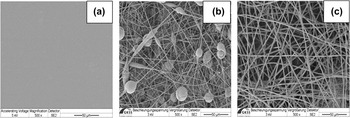
The polymer samples (20 × 20 mm2) were prepared from poly(etherimide) (PEI, Ultem® 1000, General Electric, New York, NY) (Fig. 1). The preparative procedures and polymer characterization were described in our previous work.Reference Krasteva, Pehlivanova, Seifert, Luetzow, Tsoneva, Richau, Lendlein and Tzoneva30 Briefly, 2D PEI-film (PEI-f) exhibited dense nonporous surface [Fig. 1(a)] characterized by root mean squared roughness R q = 2.3 nm and roughness ratio (i.e., true polymer surface area divided by the projected sample area) r = 1 (both obtained with AFM Multimode IIIa, contact mode, scan size 10 × 10 µm2, software version 5.31R1). For 3D PEI-1 [fiber diameter distribution from 0.4 up to 1.8 µm with its maximum at 0.9 µm, whereby the single fibers contained beads of 10 µm, as shown in Fig. 1(b)] and PEI-2 [fiber diameter distribution from 0.6 up to 2.4 µm with its maximum at 1.6 µm, Fig. 1(c)], an accessible polymer surface area per cm2 sample can be roughly estimated from fiber diameter and preparation process parameters to account 16 cm2/cm2 for PEI-1 with a sample thickness of 146 ± 5 µm and 96 cm2/cm2 for PEI-2 with a samples thickness of 500 ± 10 µm. Their microporous sample surfaces are characterized by a mean open surface area of 7.7 ± 0.1 µm2 (PEI-1) and 9.5 ± 1.4 µm2 (PEI-2), corresponding to surface porosities of 62 ± 3% and 73 ± 3%, respectively (obtained from two scanning electron micrographs at different locations, FEI PHENOM 1.0 (Eindhoven, Netherlands), scan size 100 × 100 µm2, software version 1.6_2.rel.6396). All nonsterilized polymer surfaces showed hydrophobic properties with advancing contact angles of about 80° and negative values of zeta-potential in the range of −40 to −50 mV at pH = 7.4. Glass coverslips (18 × 18 mm2) with typical hydrophilic surface (advancing contact angle of 24°) were used as reference samples. Sterilization of all materials was performed by autoclaving at 121 °C for 20 min.
Surface images of the PEI materials: (a) PEI–f, (b) PEI–1, and (c) PEI–2.

B. Proteins
Fibronectin (FN; Cat. No. F-2006, Sigma-Aldrich Chemie GmbH, Munich, Germany) isolated from human blood serum was used for protein adsorption studies onto the materials.
C. Device for electrotreatment
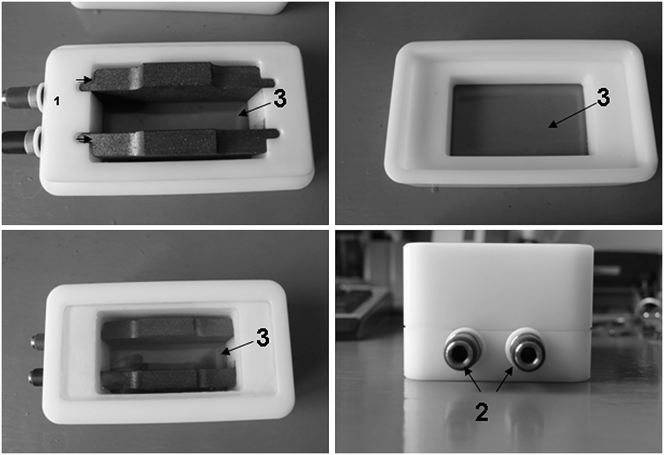
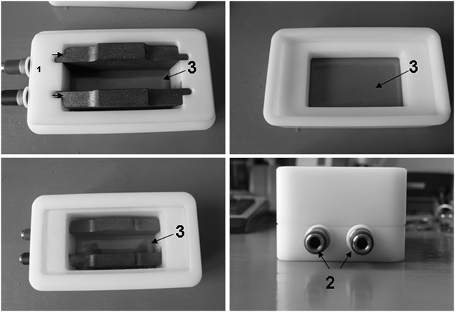
The module for electrotreatment experiments (Fig. 2) is described in Ref. Reference Krasteva, Pehlivanova, Seifert, Luetzow, Tsoneva, Richau, Lendlein and Tzoneva30. The electrotreatment was conducted at effective intensity of the sinusoidal EF Е of 2.46 V/cm and frequency of 1–100 Hz. Prior to experiments, the chamber was subjected to steam sterilization.
Device for electrotreatment: 1—graphite electrodes, 2—stainless plugs, 3—glass window.
D. Protein adsorption onto polymer materials under EF
The polymer samples were prewetted shortly with 70 vol% ethanol and rinsed intensively with phosphate buffer saline (PBS, pH 7.4) and distilled water. The sample was placed at the bottom of the device between and under the electrodes. The distance between the electrodes was adjusted to 1 cm. The effective surface area of the samples under EF was 2 cm2 for polymer materials and 1.8 cm2 for glass, respectively. The surface area for nonelectrotreated samples was 4 cm2 for polymers and 3.24 cm2 for glass, respectively. FN dissolved in PBS (3 mL) in a concentration of 0.05 mg/mL was added to the samples. The electrotreatment lasted for 1 h at room temperature (RT).
E. Polyacrylamide gel electrophoresis (SDS-PAGE)
SDS-PAGE was used for estimation of the amount of adsorbed FN on the polymer material. The detailed procedure is described in Ref. Reference Krasteva, Pehlivanova, Seifert, Luetzow, Tsoneva, Richau, Lendlein and Tzoneva30. The proteins adsorbed onto the polymer materials and glass were desorbed with 2.5 wt% solution of sodium dodecyl sulfate (SDS) in PBS for 1 h at RT. The protein samples were loaded on NuPAGE® Bis-Tris Gel 4–12 % (1.5 mm gel thickness, Invitrogen, Cat. No. NP0336BOX, Life Technologies GmbH, Darmstadt, Germany). The staining of the gels was done with Silver Xpress® staining kit (Invitrogen, Cat. No. LC6100 Life Technologies GmbH, Darmstadt, Germany). “ImageJ” software was used for estimation of the relative (optical) intensity (r.i.) of the protein bands.Reference Krasteva, Pehlivanova, Seifert, Luetzow, Tsoneva, Richau, Lendlein and Tzoneva30,31 For protein reference, an FN solution (10 μg/mL) was used, which was directly loaded to the gel.
F. Vital/dead (FDA/PI) staining
L929 mouse fibroblasts from connective tissue (ATCC, Cat. No. CCL-1) were cultivated in Eagle’s MEM (Biochrom, Cat. No. F0385) with 10 vol% horse serum (ATCC, Cat. No. 30–2040), 7.5 wt% NaHCO3 (Sigma, Cat. No. S-8761), and 1 vol% Pen/Strep+L-Glutamin (Invitrogen, Cat. No. 10,378-016). One milliliter of the cell suspension with a cell density of 1.5 × 10⁵ cells per mL was plated on polymer samples, and cover glasses were preadsorbed with FN (20 µg/mL for 30 min) in 6-well plates. Cells adhered for 24 h and got a vital staining. A stock solution of fluorescein diacetate (FDA, Sigma, St. Louis, MO) was prepared by dissolving 5 mg/mL in acetone. One milligram of propidium iodide (PI, Sigma) was dissolved in 1 mL of water to get a stock solution of PI. The working solution of FDA/PI was freshly prepared by adding 5 μL of FDA stock solution and 2 μL from PI stock solution to 1 mL of prewarmed cell culture medium without phenol red. The cells adhered to each polymer sample were incubated at 37 °C and 5% CO2 with the above staining medium for 5 min. Then the samples were scanned on Confocal Laser Scanning Microscope LSM 510 Meta (Carl Zeiss Mikroskopsysteme, Jena, Germany) using the HeNe and Argon lasers.
G. Actin staining
L929 mouse fibroblasts were cultivated for 24 h on the samples and then electrotreated in a basal cell medium for 1 h at 37 °C. After the incubation period the samples were rinsed three times with PBS (pH 7.4). The adhered cells were fixed by 1 mL 3 wt% solution of paraformaldehyde (Sigma, Cat. No. 158127) for 15 min at RT. The fixed cells were permeabilized using 1 mL 0.5 vol% solution of Triton X-100 (Sigma, Cat. No. T-8787) for 5 min and then incubated with 1 mL 1 wt% solution of bovine serum albumin (Sigma, Cat. No. 85040C) for 15 min. The samples were washed three times with PBS and incubated for 30 min at RT with 4 U/mL BODIPY 558/568 phalloidin (B3475, Invitrogen GmbH, Karlsruhe, Germany). Again, the samples were washed three times with PBS and once with distilled water and were installed on microscope slides with Mowiol (Sigma, Cat. No 81,386). Preparations were analyzed using inverted fluorescent microscope (Leica DMI3000 B, Leica Microsystems GmbH, Germany).
III. RESULTS AND DISCUSSION
A. SDS-PAGE
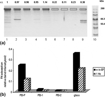
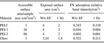
The prewetting of polymer surface was performed to ensure the equilibration of the surface and to prevent the protein damage by keeping the surface wet before protein adsorption. The wetting procedure did not change surface characteristics of the materials like contact angle (data not shown). The relative (optical) intensity (r.i.) of the FN bands of the nonEF treated samples showed no essential differences [Fig. 3(a), Lanes 1–5]. When EF is applied, the adsorption of FN was diminished as a whole [Fig. 3(a), Lanes 6–9]. Considering the accessible polymer surface area of fibrous materials per geometrical sample area (16 cm2/cm2 for PEI-1 and 96 cm2/cm2 for PEI-2) and the exposed geometrical surface area of the samples, the FN adsorption expressed can be calculated as relative band intensity per square cm [Table I and Fig. 3(b)]. The calculated values of the adsorbed FN showed that fibrous materials (PEI-1 and PEI-2) adsorbed less protein amount than PEI-f or glass.
(a) SDS-PAGE of fibronectin adsorbed on and desorbed from polymers. Lane 1—fibronectin (10 µg/ml); Lanes 2–5—without EF: Lane 2—PEI-f, Lane 3—PEI-1, Lane 4—PEI-2, Lane 5—glass; Lanes 6–9—1 Hz: Lane 6—PEI-f, Lane 7—PEI-1, Lane 8—PEI-2, Lane 9—glass; Lane 10—protein standard Mark 12. (b) Graph of FN adsorption expressed as relative 200 kDa-band intensities of the materials per square cm (Ref. Reference Krasteva, Pehlivanova, Seifert, Luetzow, Tsoneva, Richau, Lendlein and Tzoneva30).

FN adsorption calculated as relative band intensity per square cm using specific surface area of the polymer materials. The FN adsorption data were calculated using accessible surface area/sample area and exposed surface area.

B. Cell viability
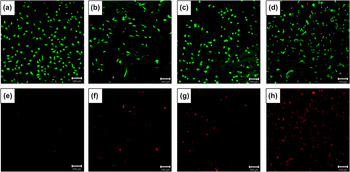
The vital/dead staining showed that a better viability is exhibited by cells cultivated on a 2D material [PEI-f, Figs. 4(a) and 4(e)]. The fibrilar 3D materials (PEI-1 and PEI-2) took an intermediate place for viability [Figs. 4(b) and 4(f), Figs. 4(c) and 4(g)], whereas glass surface [Figs. 4(d) and 4(h)] showed the lowest viability [many nonvital cells in Fig. 4(h)].
Vital/dead staining with FDA/PI of cells on PEI-f [(a) and (e)], PEI-1 [(b) and (f)], PEI-2 [(c) and (g)], and glass [(d) and (h)]. The cells are cultivated 24 h on FN-coated surfaces and stained for FDA [(a), (b), (c), and (d)] and for PI [(e), (f), (g), and (h)]. Bar is 100 μm.

C. Cell adhesion
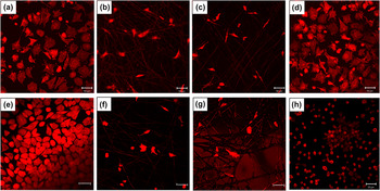
Figure 5 shows fluorescence images of cells attached on PEI-f, PEI-1, PEI-2, and glass labeled with BODIPY 558/568-conjugated phalloidin. The morphology of the cytoskleleton in adherent cells differs on 2D and 3D polymer materials. While cells on 2D films [Figs. 5(a)–5(e)] showed typical, well-spread polygonal shape with well-pronounced stress fiber formation, on 3D biomimetic polymer fibers [Figs. 5(b) and 5(f), Figs. 5(c) and 5(g)], cells were bipolar showing dendritic type cell morphology with less stringent cytoskeletal organization. On 3D fiber materials (which are in the low micrometer scale), the cells had the tendency to align on the individual fibers rather than growing randomly as can be seen on the nanofibrous scaffold.Reference Soliman, Sant, Nichol, Khabiry, Traversa and Khademhosseini32 The rather small mean open surface area (7.7 µm2 for PEI-1 and 9.5 µm2 for PEI-2) of the nonwoven that is an order of magnitude smaller than the dimensions of the cellsReference Balguid, Mol, van Marion, Bank, Bouten and Baaijens33,Reference Sell, Barnes, Simpson and Bowlin34 is most probably the reason, which hinders the uniform penetration of the cells through the scaffold. Reduced oxygen and nutrient diffusions also limit the penetration depth of the cells.Reference Kim and Kim35 As a result, cells are only able to survive close to the surface.
L929 cells were plated on PEI-f [(a) and (e)], PEI-1 [(b) and (f)], PEI-2 [(c) and (g)], and glass [(d) and (h)]. (a), (b), (c), and (d) are controls without EF exposure. E, F, G, and H are cells electrotreated with 1 Hz. All cells are stained for actin. Bar is 50 μm.

In general for control samples without EF exposure (upper panel of Fig. 5), PEI-f and glass attracted more cells than 3D scaffolds (PEI-1 and PEI-2). The applied AC EF induced different effects on cell adhesion depending on the substrate type. Exposure of cells for 1 h to 1 Hz EF slightly improved cell adhesion and spreading on the 2D polymer material [Fig. 5(e)], while the number of adhered cells on 3D nonwoven was not altered [Figs. 5(f) and 5(g)].
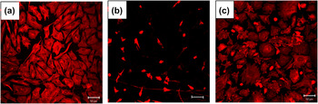
Additional cell adhesion experiments were conducted with 10 Hz and 100 Hz electrotreatment on PEI-f, PEI-2, and glass (Fig. 6). Exposure of cells for 1 h to 10 Hz EF slightly improved cell adhesion and spreading on 2D polymer material [Fig. 6(a)] as well as the number of adhered cells on 3D nonwoven [Fig. 6(b)]. When cells were exposed to 100 Hz EF almost no adhered cells were detected (data not shown). In the recent years, the effects of low frequency (in the range of 0.1–10 Hz) AC EFs of physiological strength (0.1–10 V/cm) on the cell function as redistribution of cell surface receptorsReference Cho, Thatte, Lee and Golan36 and reorganization of microfilament structureReference Cho, Thatte, Lee and Golan28 have been described. At the same time, the application of AC field with a higher frequency (60–120 Hz)Reference Cho, Thatte, Lee and Golan27,Reference Cho, Thatte, Lee and Golan28 did not cause any changes in the above cellular structures. It can be supposed that the alteration in the organization of the above structures by the applied low frequency AC field may lead to changes in cell functions such as cell adhesion, spreading,Reference Stossel29,Reference Bretscher37 and migration.Reference Cho, Thatte, Lee and Golan36 Based on these data, we assume that the improved cell adhesion in our study by the application of AC field with frequency of 1 and 10 Hz is due to the changes in reorganization of the cytoskeleton and cell surface receptors. The lack of changes in cell structures is most probably the reason for the poor cell adhesion at 100 Hz.
L929 cells were plated on PEI-f (a), PEI-2 (b), and glass (c). Cells are electrotreated with 10 Hz and stained for actin. Bar is 50 μm.

Cells cultivated on a glass surface showed an interesting cell adhesion behavior [Figs. 5(d) and 5(h); Fig. 6(c)]. Nonelectrotreated cells and cells treated with 10 Hz [Fig. 6(c)] were well spread, whereas cells treated with 1 Hz showed round shape [Fig. 5(h)]. One possible explanation of that result could be the most expressed degradation of FN (adhesive ligand), probably caused by EF application, to minor protein bands at 1 Hz [visible small electrophoretic bands between 55.4 and 66.3 kDa on Fig. 3(a), Lane 9], which could alter the cell adhesion. That interesting result needs to be further investigated and proved.
IV. CONCLUSION
Our investigation of the effects of AC EF on adsorption of the protein FN and cell adhesion onto 2D and 3D structured polymeric materials shows that FN is adsorbed onto the investigated materials in a lower amount under the applied EF compared with the situation of no EF application. In addition, fibrous materials (PEI-1 and PEI-2) adsorbed less protein than PEI-f and glass, if the accessible polymer surface area is taken into account. Cell adhesion was better presented on 2D materials than on 3D scaffolds. Most probably the combination of insufficient FN adsorption, fiber diameter (which is in the low micrometer scale), and the microscaled pores on the surface of the fibers is the reason for the poor cell adhesion to the fibrous materials. The application of AC EF (between 1 and 10 Hz) improved cell adhesion, whereby this effect is better visible for 2D polymers. Further experiments for optimizing the 3D polymer design in terms of pore size of the scaffolds and fiber's diameter with respect to increased protein adsorption and cell adhesion are needed.
ACKNOWLEDGMENTS
The authors thank Maik von Ruesten-Lange for providing PEI film. This work is supported by a grant of a bilateral scientific grant of DAAD (DO 02-326 and D/08/02060), BMBS COST Action TD1104, EP4Bio2Med, and European Social Fund (BG051PO001–3.3.04/42).