I. INTRODUCTION
Worldwide interoperability for microwave access (WiMAX) is a wireless communications standard designed to provide a high speed data rates. Its capability to deliver high-speed Internet access and telephone services to subscribers enables new operators to compete in a number of different markets. In urban areas already covered by digital subscriber line (DSL) and high-speed wireless Internet access, WiMAX allows new entrants in the telecommunication sector to compete with established fixed-line and wireless operators. The increased competition can result in cheaper broadband Internet access and telephony services for subscribers. In rural areas with limited access to DSL or cable Internet, WiMAX networks can offer cost-effective Internet access and may also encourage the Universal Mobile Telecommunications System/High Speed Downlink Packet Access operators to extend their networks into these areas.
WiMAX is designed to operate in the frequency range 2–6 GHz especially in the frequencies 2.3, 2.5, 3.3, 3.5, 5, and 5.5 GHz [Reference Reha, El Amri, Benhmammouch and Oulad Said1–Reference Kaur6].
Wireless local area networks (WLAN) is a wireless computer network that links two or more devices using a wireless distribution method within a limited area such as home, school, computer laboratory, or office building. This gives users the ability to move around within a local coverage area and still be connected to the network, and can provide a connection to the wider Internet. WLAN is designed to operate for 2.4–2.5 GHz (802.11b/g/n), 3.6 GHz (802.11y), 4.9–5.9 GHz (802.11a/h/j/n/ac/y/p), 900 MHz (802.11ah) and 60 GHz (802.11ad) frequencies bands [Reference Reha, El Amri, Benhmammouch, Oulad Said, El Ouadih and Bouchouirbat3, Reference Perahia and Stacey7, Reference Gast8].
In this paper, a coplanar waveguide (CPW)-Fed Slotted CANTOR Set fractal antenna is designed for 2.5/3.3/5/5.5 GHz WiMAX, and for 2.4–2.5/4.9–5.9 GHz WLAN applications. First we describe the antenna design, after that, we study the behavior of the antenna when we increase the number of iterations. Next, we discuss the behavior of the antenna when we add slots and finally we compare simulated and measured results.
II. LITERATURE REVIEW OF CANTOR SET FRACTAL ANTENNAS
A) The CANTOR Set fractal geometry
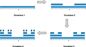
CANTOR Set was invented by the German mathematician Georg CANTOR. It is built iteratively from the segment (0, T) by removing a central portion (a third for example); then the operation is repeated on the remaining two segments, and so on. Figure 1 shows the steps to generate the four first iterations of CANTOR Set structure [Reference Reha, El Amri, Benhmammouch and Oulad Said9].
The generation of the four first iterations of the CANTOR Set structure [Reference Reha, El Amri, Benhmammouch and Oulad Said9].

The HAUSDORFF dimension of the CANTOR Set fractal is given in (1) [Reference Reha, El Amri, Benhmammouch and Oulad Said9].
 $$d = \displaystyle{{ln (n)} \over {ln (h)}} = \displaystyle{{ln (2)} \over {ln (h)}},$$
where “n” is the number of generated copies and “h“ is the reduction factor. If h = 3, the HAUSDORFF dimension is 0.6.
B) The use of CANTOR Set fractal structure for antenna design
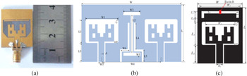
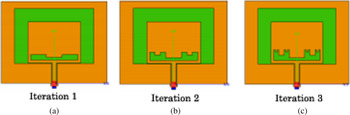
According to our literature review [Reference Reha, El Amri, Benhmammouch and Oulad Said9], Yingsong Li et al. designed some antennas based on a modified CANTOR Set fractal structure, suitable for ultra-wideband (UWB) applications (Fig. 2) [Reference Li, Yang, Liu and Jiang10–Reference Li, Li, Liu and Jiang12]. Also, El amri et al. designed a miscrostrip patch antenna with CANTOR Set fractal slots for long term evolution (LTE) and radio frequency identification (RFID) applications (Fig. 3) [Reference El Amri, Reha, Benhmammouch, Saih and Oulad Said13].
CANTOR Set fractal antennas designed by Yingsong Li et al. (a) [Reference Li, Yang, Liu and Jiang10], (b) [Reference Li, Li, Liu and Jiang11], and (c) [Reference Li, Li, Liu and Jiang12].

Miscrostrip patch antenna with CANTOR Set fractal slots designed by El amri et al. (a – iteration 1), (b – iteration 2), and (c – iteration 3) [Reference El Amri, Reha, Benhmammouch, Saih and Oulad Said13].

III. ANTENNA DESIGN AND OPTIMIZATION
A) CPW-Fed CANTOR Set fractal antenna design
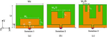
Figure 4 illustrates the geometry of the proposed CANTOR Set fractal antenna. The antenna is printed on a substrate FR4 with relative permittivity 4.4, a loss tangent of 0.03, and a thickness of 1.6 mm. The size of the antenna is 50 × 42 mm2 (L s × W s ). The proposed antennas consist of three iterations of CANTOR Set fractal radiation patch, and a 50 Ω CPW-fed structure. The 50 Ω CPW-fed structure consists of a CPW transmission line with a signal strip width W f = 3.3 mm and gap between the CPW ground plane and transmission signal strip with width s = 0.32 mm. The 50 Ω CPW structure of the proposed UWB antenna is designed by using the standard equations [Reference James and Hall14, Reference Garg15]. The other parameters are: W p = 34.9, L p = 11.63, and L g = 5 mm.
The proposed CPW-Fed CANTOR Set fractal antennas (a – iteration 1), (b – iteration 2), and (c – iteration 3).

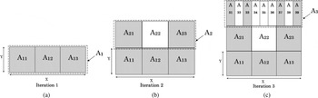
The CANTOR Set fractal radiation patch can be designed using the following procedures, which are shown in Fig. 5.
Construction of CANTOR Set fractal antenna (a – iteration 1), (b – iteration 2), and (c – iteration 3).

The first iteration is composed by a rectangular patch (Set A1 – Fig. 5(a)) with dimensions (X x Y), the second iteration is the union of A1 and A2. The Set A2 is the same as A1 with the suppression of the middle Subset A22. In the third iteration, the same procedure is repeated. The dimension Y can be postulated by using equations (2) and (3) [Reference Simons16].
 $$\varepsilon _{eff} \approx \displaystyle{{\varepsilon _r + 1} \over 2},$$
 $$Y = \displaystyle{C \over {2.f_r. \sqrt {\varepsilon _{eff}}}}, $$
where ε eff is the effective dielectric constant, ε r is the relative dielectric constant; Y is the width of the first iteration CANTOR Set fractal radiation patch; C is the speed of light; and f r is the resonant frequency. For example, if Y = L p = 11.63 mm, the theoretical resonant frequency is 7.8 GHz.
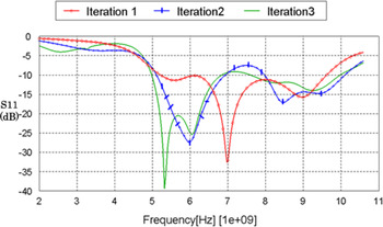
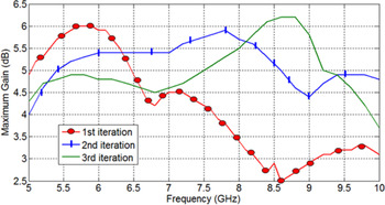
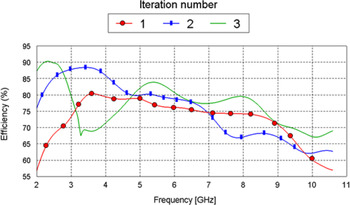
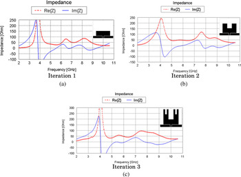
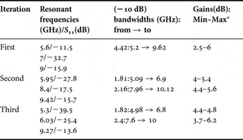
Through numerical simulations, the three iterations of the CANTOR Set fractal antenna demonstrate a return loss below −10 dB over a wide frequency ranges (Fig. 6). Also, we observe that the maximum gain of the antennas varies between 2.5 and 6 dB for the first iteration, between 4 and 5.9 dB for the second iteration and between 3.7 and 6.2 for the third iteration (Fig. 7). The behavior of the efficiency versus frequencies and iteration numbers is shown in Fig. 8. The impedances of the three iterations of the proposed antennas are shown in Fig. 9. We can observe that there is a good matching in the band of 4.8–7 GHz. Table 1 summarizes for each iteration, the resonant frequencies, the S 11 value on the resonant frequencies, the −10 dB bandwidths, and the maximum gains on the −10 dB bandwidths.
Simulated S 11 parameter versus frequencies for the three iterations.

The simulated maximum gains of the three iterations.

The simulated efficiency of the three iterations.

The simulated impedance of the three iterations (a – iteration 1), (b – iteration 2), and (c – iteration 3).

Simulated resonant frequencies and bandwidths for the three iterations of the CANTOR Set fractal antenna.

* The gain is simulated on the (−10 dB) bandwidth.
B) Setup of the slots on the CPW-Fed slotted CANTOR Set fractal antenna (3rd iteration)
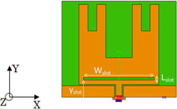
To create other resonance frequencies, a rectangular slot is setup on the 3rd iteration of the proposed antenna. The positions of the slot and their dimension are Y slot , Wslot , and L slot (Fig. 10).
The slotted CPW-Fed CANTOR Set fractal antenna (3rd iteration).

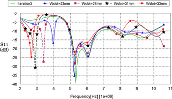
Figure 11 shows the variation of simulated S 11 with changing W slot parameter. The other parameters are: L slot = 1 and y slot = 7.5 mm.
Simulated S 11 parameter versus frequencies and versus the W slot for the 3rd iteration CANTOR Set fractal antenna.

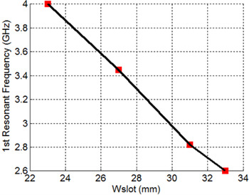
As shown, the new resonance frequency decreases when the W slot increases and Fig. 12 shows the relationship between the first resonant frequency and the length of the slot (W slot ).
The first resonant frequency versus the length of the slot (W slot ).

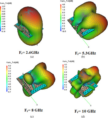
Figure 13 shows the simulated three-dimension (3D)-total gain pattern when W slot = 33 mm for some frequencies (2.6, 5.3, 8, and 10 GHz).
Simulated 3D-total gain pattern for the frequencies 2.6 (a), 5.3 (b), 8 (c), and 10 GHz (d) when W slot = 33 mm.

Although the antenna has a low S 11 on the frequencies bands 7.5–8.2 and 9.5–10.5 GHz, the shape of simulated 3D radiation pattern is not stable with important side lobes due to the presence of high propagation modes. However, for the other frequencies bands 2.35–2.8 and 4.9–6.6 GHz, simulated 3D radiation pattern is bidirectional, stable, and with low side lobes.
IV. MANUFACTURING AND MEASUREMENT OF THE PROPOSED ANTENNAS
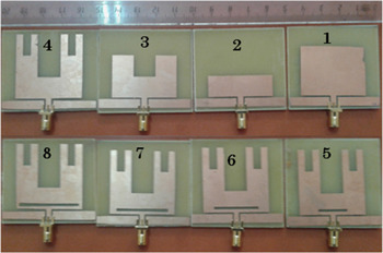
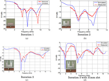
Figure 14 shows a photograph of the manufactured antennas with the dimensions as listed previously. The measured and simulated result for the reflection coefficient of some proposed antenna is shown in Fig. 15. The reflection coefficient magnitude was measured using HP 8719C Vector Network Analyzer.
The manufactured prototypes of the proposed antennas.

Measured and simulated reflection coefficient of the antenna (a – iteration 1), (b – iteration 2), (c – iteration 3), and (d – iteration 3 with 33 mm slot).

Due to manufacturing imperfections (like inaccuracy in the milling and etching processes and connector soldering), the measurement results are not exactly similar to the simulated results. Some measured resonance frequencies are shifted from those simulated.
Also, some differences between measured and simulated S 11 are observed. As shown in Fig. 15(a), the measured S 11 for the first resonant frequency (5.8 GHz) is very low compared with the simulated one, for the second resonant frequency (7 GHz), the simulated S 11 is very low compared with the measured one, and for the last resonant frequency (9.3 GHz), the measured S 11 is very low compared with the simulated one. The same thing is observed in Fig. 15(b) for the last resonant frequency and in Fig. 15(c) for the second and the last resonant frequencies.
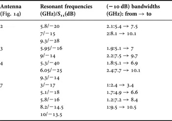
Table 2 summarizes for some measured antennas, resonant frequencies, S 11 values on the resonant frequencies and (−10 dB) bandwidths.
Measured resonant frequencies and bandwidths for some manufactured antennas.

Due to previous results and due to the stability of the 3D total gain pattern in some frequencies bands, the three iterations of CANTOR Set fractal antenna are a broadband antennas adequate for 5.5 GHz WiMAX and 5.9 GHz WLAN applications. Also, the 3rd iteration slotted CANTOR Set fractal antenna with a 31 mm slot length is a broadband antenna adequate for 2.5/3.3/5/5.5 GHz WiMAX and for 2.4–2.5/4.9–5.9 GHz WLAN.
V. CONCLUSION
The fractal concept is one of the better solutions to design simple, low profile, and miniaturized antennas; the use of the CPW-Fed slotted CANTOR Set Fractal antenna with a ground plane on the same plane as the radiating element allows having a broadband antennas with a lot of resonant frequencies and good efficiency.
The proposed antennas are manufactured on a (50 × 42 mm2) FR-4 substrate and their S 11 are measured and shows a good impedance matching. Thereby, these results make this antennas an adequate candidates for some wireless applications such as 2.5/3.3/5/5.5 GHz WiMAX and for 2.4–2.5/4.9–5.9 GHz WLAN.
As perspective of this work, more refinement can be done to obtain antennas with better performances, good impedance matching and low side lobes. Also, other measurements should be done to confirm the accuracy of these results, especially, the efficiency and the gain measurement.
ACKNOWLEDGEMENT
All authors would like to thank RITM Laboratory of ESTC CASABLANCA, Telecoms laboratory of Royal Air Academy and Electronic Laboratory of IGA MARRAKECH for providing support and assistance to perform measurements.
 Abdelati Reha was born in Casablanca-Morocco in 1975. He received his Engineering degrees in Aeronautic from Royal Air Academy of Marrakech-Morocco in 1999, and in Telecommunication from INPT-Rabat-Morocco in 2002. He is currently working toward the Ph.D. degree at RITM Laboratory in ESTC- Hassan II University – Casablanca-Morocco. His main research interests are in Fractal Antennas, UWB Applications.
 Dr. Abdelkebir Elamri a Ph.D. in Signals and Systems from University of Montpellier 1990 (FRANCE), is currently a professor in Electrical Engineering Department at Technology School of Casablanca (ESTC). He is a member of RITM laboratory. His research interests include characterization, modeling antennas for telecommunications applications, radar and mobile radio.
 Dr. Othmane Benhmammouch was born in Mohammedia, Morocco, in 1982. He received a Master in Computer-sciences from Université de Versailles, France, in 2005 and a Master in Applied Mathematics from the Ecole Normale Supérieure de Cachan (ENS Cachan), France, in 2006. He received a Ph.D. in Electronic Engineering from Université de Bretagne Occidentale, Brest, France. In 2012 he joined the Centre Scientifique et Technique du Batimrent (CSTB), Nantes, France as a postdoctoral researcher and works in EMW propagation prediction in Telecommunications. Since September 2015 he is an Assistant Professor in International University of Casablanca. His main research interests include EMW propagation prediction, Fractal Antennas, Antennas Design, and Numerical Analysis.
 Dr. Ahmed Oulad Saïd was born in Tetouan (Morocco) in 1961. He received his license degree in Physics in 1983 from the Faculty of Sciences of Rabat, and DEA in Instrumentation and measurements from the University of Bordeaux I France in 1984. In 1987 he received his Ph.D. degree in Microwave at the University of Bordeaux I France. He is the Head of Electrical and Telecommunications Department in the Royal Air Academy. His main research interests are in Fractal Antennas, UWB Applications, Microwaves, MIMO antennas, Optical Fibers. He is the head of the Association of Modeling and Simulation in the Enterprises – Section Morocco (AMSE).
 Dr. Abdelhakim El Ouadih was born in Casablanca-Morocco in 1976. He received his Engineering degrees in Aeronautic from the Royal Air Academy of Marrakech-Morocco in 1999, and in Telecommunication from the INPT-Rabat-Morocco in 2002. He received his Master degree and Ph.D. degree in Telecommunication from Kadi Ayyad University, Marrakech-Morocco. He is currently a professor in the Royal Air Academy, Marrakech-Morocco. His main research interests are in Antennas, Propagation and Wireless Communication.
 Marouane Bouchouirbat was born in Marrakech-Morocco in 1986. He received his Engineering degree from the High Institute of Applied Engineering of Marrakech-Morocco in 2012. He is a professor in the IGA-MARRAKECH. His main research interests are in automation, telecommunication, and electric systems.