Introduction
New generation geostationary-orbit (GEO) communication satellites provide high channel capacity by the cellular coverage technique. Cellular coverage provides frequency re-use capability and increases the overall communication system throughput [Reference Fenech, Amos, Tomatis and Soumpholphakdy1]. A multi-beam antenna can create spots of this coverage. Applying a phased array antenna (PAA) is one of the best approaches for achieving simultaneous multiple beams [Reference Bhattacharyya2]. Since spot beams in a GEO satellite have high gains and large antenna size, the most important challenge in the realization of this kind of antennas is size reduction. One of the most effective methods for decreasing the multiple beam array size is the sub-beam concept [Reference Kilic and Zaghloul3]. In this method, sub-beams with lower peak gains are used resulting in an overall reduced aperture size of the array. It can be proved that the sub-beams with lower gains and broader beam patterns do not raise the co-channel interference intensely. Digital beam-forming network (BFN) is the technique, which has been proposed in [Reference Kilic and Zaghloul3] for the implementation of a multi-beam antenna in conjunction with the sub-beam concept. This method is applicable for narrow-band signals, because the processing speed of the digital processors is limited. To overcome these limitations, a microwave BFN for implementation of a multiple beam PAA incorporating the sub-beam concept is proposed.
Implementation of a PAA with a large number of elements is practically impossible without dividing it into several sub-arrays. In the conventional active PAAs, a large number of active components are needed for feeding the array elements, and the configuration of the array feeding network becomes very complex and usually unfeasible.
The radiation pattern of an array, which is divided into several sub-arrays differs from the primary array. Excitation matching is a method which tries to minimize this difference by adjusting the exciting sets of the sub-arrays. In this technique, the norm of the difference between the optimum excitation set and the excitation set of the array (which consists of sub-arrays) is minimized. Excitation matching technique was widely used for arrays, which generate the sum and difference patterns simultaneously [Reference Namara Mc4–Reference Manica6].
As an alternative, the tile configuration was used for dividing an array into several sub-arrays. In [Reference Jacomb-Hood and Lier7], a multiple beam PAA with super-tile composition was proposed. This approach is cost-effective and provides reconfigurability for the satellite payload, but grating lobes appear outside the coverage region.
Dividing an array into a number of sub-arrays has some consequences such as the appearance of grating lobes, which is a result of increased distance between central points of the array divisions. Several approaches were suggested for eliminating grating lobes. In the overlapped sub-arrays method, the grating lobes are filtered out by creating a rectangular sub-array factor. The rectangular sub-array factor is produced by exciting the sub-array elements proportional to a Sinc function. As much as the Sinc function is extended, the sub-array factor will be closer to an ideal rectangular function. For extending the Sinc function, in addition to the main sub-array, the neighboring elements should be excited. The overlapped sub-array is efficient in removing the grating lobes, but its BFN is very complex [Reference Mailloux8–Reference Petrolati10].
An alternative method for eliminating grating lobes is the interleaved sub-arrays [Reference Chou11]. In this technique, each sub-array is excited with a separate Butler matrix (BM) [Reference Butler and Lowe12]. For retaining the same main beam peak directions, specific extra phase shifts were added to the input ports of the BMs [Reference Chou11]. By using skirt elements in two sides of the core array, the side lobe level (SLL) of each beam decreases and the carrier to interference ratio improves. Incorporating planar interleaved sub-arrays, multiple beams in two dimensions, and orthogonal beam forming while keeping extra small angular distance between adjacent sub-beams are properties of the designed antenna in this paper which have not been considered and discussed in [Reference Chou11], and thus make this study distinct from others such as [Reference Chou11].
In this paper, a PAA that can generate multiple sub-beams has been synthesized. The angular distance between the sub-beams is smaller than that of the main spot beams, and it imposes severe constraints on the BFN that is intended for generating orthogonal beams. The innovation of current paper is the application of the interleaved sub-array technique for implementation of a planar multiple beam PAA incorporating the sub-beam concept in two dimensions of the coverage domain. In this study, a novel microwave BFN that can generate multiple orthogonal sub-beams and satisfy all the requirements of the antenna will be designed and analyzed.
For further understanding, a numerical example with analysis results is presented. In the first step, the requirements of an antenna with multiple sub-beams will be derived from general constraints. Next, an array, which is composed of interleaved elements will be synthesized and optimized using genetic algorithm (GA). Furthermore, the gain patterns of sub-beams and the carrier to interference ratios in one of the coverage spots will be calculated. In addition, the amount of aperture size reduction in the sub-beam method compared to a typical multiple beam array will be presented.
Array aperture size reduction
High gain of multiple beam antennas in GEO satellites has made the aperture size reduction a necessity. The array aperture size depends on the aperture efficiency of each array element, the amplitude distribution of the array elements, and the main beam peak gain.
In the case that the radiating element of the array is a microstrip patch antenna, the array should be decomposed into several sub-arrays. The maximum aperture efficiency of each array element would be achieved if the patch elements’ spacing is not more than λ [Reference Bhattacharyya2], where λ is the wavelength in free space.
The selection of a proper method for array amplitude distribution is important for array aperture size reduction. An array with uniform amplitude distribution has the highest peak gain and maximum aperture efficiency compared to other amplitude distributions, but its SLL is not reasonable.
In the array with multiple spot beams, the required peak gains for the main beams can be reduced by using the sub-beam method [Reference Kilic and Zaghloul3]. In this method, each spot is composed of 3, 4, 7, 9, and so on sub-beams [Reference Macdonald13]. The sub-beams of each spot have the same frequency band. The beam contour level (crossover level) is the ratio of the peak gain to the gain at the edge of coverage (EOC). Sub-beams and main spots exhibit the same gain in their EOC but their contour levels are different. Sub-beams have lower contour levels and their beams are flatter in comparison with the main spot beams. It means that the beam peak gain of the sub-beams is lower than the main spot beams. As a result, the antenna aperture size is reduced. In the next sections, a proper synthesis method for a reduced sized planar-phased array will be described, which can generate multiple sub-beams.
Array synthesis concerning multiple sub-beam constraint
The most important constraint in the synthesis of an array that is used for creation of sub-beams is the extra small angular distance between adjacent sub-beams. In this paper, the synthesis technique of a planar array with interleaved sub-arrays has been presented. The present array is different from previous study [Reference Chou11] in: (1) exertion of above-mentioned constraint and (2) creating multiple beams in two dimensions. It has been shown that the above-mentioned constraint affects the phase of lateral elements (skirt elements). In addition, it has been demonstrated that this constraint obliges the designer to specify unequal values for the number of elements in each sub-array and the number of sub-beams. As a result, a BFN that is different from the BFN in [Reference Chou11] has been developed in this paper.
An array with orthogonal beams requires conditions (1) and (2) for angular distances between adjacent beams [Reference Bhattacharyya2]. In (1) and (2), P x and P y are the numbers of beams in the x and y directions. $\Delta \sin \theta _{peak_x}$ and $\Delta \sin \theta _{peak_y}$
 are related to the angular distances between peak points of the adjacent beams in the x and y directions. In a planar array which has been decomposed into some sub-arrays with interleaved elements in both x and y directions, the spacing period of sub-array elements in the x direction is d sx = N sxd x, and in the y direction it is d sy = N syd y, where d x and d y are element spacing, and N sx and N sy are the number of sub-arrays in the x and y directions, respectively:


Since the number of beams is one of the design requirements, N sxd x/λ and N syd y/λ should have values that satisfy (1) and (2). This constraint results in large amounts of N sxd x/λ and N syd y/λ. These conditions make array synthesis difficult, because d x and d y depend on N sx and N sy, respectively, and cannot be chosen independently. Increasing the number of sub-arrays leads to fewer elements in each sub-array. Therefore, in the present array synthesis, P x and N x and also P y and N y may attain separate numbers. Under this condition, the designer would devise a BFN with unequal numbers of beams and element ports for each sub-array.
Calculation of array factor of a planar array with multiple beams in two dimensions
In this sub-section, a planar array, which can generate multiple beams in two dimensions (x and y directions) has been synthesized. In [Reference Chou11], a planar array with multiple beams in one dimension (x direction) was analyzed. The array plane is coincident with the x–y plane as illustrated in Fig. 1. Decomposition of an array into interleaved sub-arrays eliminates the grating lobes in the visible region. In [Reference Chou11], a planar array with interleaved sub-arrays in each row (x direction) was analyzed. The array factor in this sub-section is different from the array factor in [Reference Chou11] due to the interleaved sub-arrays in two dimensions. Figure 2 shows an arbitrary row of an array with interleaved sub-arrays and lateral elements (skirt elements).
Model of a planar array with multiple beams in two dimensions.

Sample row of an array with interleaved sub-arrays and skirt elements.

The α x and α y are the parameters, which depend on the beam indexes in the x and y directions (α xi and α yi), respectively. These parameters can be calculated using (3) and (4). In this design, the origin of coordinate system is assumed in the middle of the beams and the number of beams is even. The beam index in the x direction (α xi) varies in the range of 1 to P x. Similarly, α yi varies between 1 and P y. Figure 3 shows α x for eight beams in the x direction.


αx, αxi, and rx for Px = 8 and Nx = 2.

Using (1) and (3), the main beam peak locations in the x direction (θ αx) for each α xi can be obtained as follows:

In a similar manner, the main beam peak locations in the y direction (θ αy) can be attained. The calculated main beam peak locations have been used in the calculation of array factor. The array factor of a planar array in the x–y plane with interleaved sub-arrays in both x and y directions is expressed in (6). This array can generate multiple beams in two dimensions.

where u = sinθ cos φ and v = sinθ sin φ. As depicted in Fig. 2, the core array consists of the interleaved sub-arrays. Each sub-array is excited with a different BFN. The phase differences ψ(α xi, a) and ψ(α yi, b) should be added to the input ports of each BFN in the x and y directions, respectively. AF subx(a) and $AF_{sub_y}( b)$ are the array factors of each sub-array in the x and y directions, respectively. The phase of elements in each sub-array is adjusted for creating orthogonal beams. The indexes of the sub-arrays in the x and y directions are denoted by letters a and b, respectively.
The AF subx(a) is calculated using (7). q x is the element index in each sub-array in the x direction, and vary from 1 to N x. N x and N y are the number of elements in each sub-array in the x and y directions, respectively. q x is shown in Fig. 2. B x(q x) is the excitation amplitude of $q_x^{th}$ element of a th sub-array in each row, and B y(q y) is the excitation amplitude of $q_y^{th}$
 element of b th sub-array in each column. AF suby (b) can be obtained in a similar manner by replacing q x, N sx, N x, u, α x, and B x(q x) in (7) with q y, N sy, N y, v, α y, and B y(q y), respectively.

ψ(α xi, a) depends on the beam index (α xi) and the sub-array index (a) in the x direction. This phase difference has been calculated using (8) [Reference Chou11]:

In a similar manner, ψ(α yi, b) can be obtained for the y direction.
Calculating phases of the lateral elements
As described in the section “Array aperture size reduction,” non-uniform amplitude distribution of an array decreases the aperture efficiency, but it may improve the other radiation parameters of the array. Consequently, the choice of the proper amplitude distribution is a trade-off between the aperture size and the antenna pattern requirements.
One of the techniques to narrow the beam-width and to reduce the SLLs in a multiple beam array with interleaved sub-arrays is the addition of some lateral elements (skirt elements) to the right and left margins of the core array [Reference Chou11]. This technique may improve the carrier to interference ratio and has been adopted in our design. Numbers of right and left skirt elements in the x direction are Nskrx and Nsklx, correspondingly, and they are equal to N skx/2. Similarly, N skry = N sky/2 and N skly = N sky/2 are the numbers of right and left skirt elements in the y direction. N skx and N sky are the total number of skirt elements in each row and column, respectively. The overall number of elements in each row of the core array is shown with N tx and is equal to N sxN x. Also, N ty is the total number of elements in each column of the core array and is equal to N syN y.
Figure 4 illustrates one row of an array with P x = 8, N x = 2, N sx = 18, and N skx = 8 that consists of some core and skirt elements. For each skirt element, a power divider is needed. As illustrated in Fig. 4, for the right skirt elements, each power divider splits the input power between the kth left core element and the kth right skirt element (embedded in BFN1s). The value of k varies from 1 to N skrx in the x direction and from 1 to N skry in the y direction. As a result, in the x direction, the amplitude coefficient of the k th right skirt element (A skrx(k)) and the corresponding left core element (A x(k)) are related as expressed in (9). Similar relation exists between the k th right skirt element (A skry(k)) and the corresponding left core element (A y(k)) in the y direction.

Designed array configuration for each row of the planar array (P x = 8, N sx = 18, N x = 2, N skx = 8).

To keep the peak locations of the beams, extra phase shifts $( \Delta \varphi _{x\_right})$ must be added to the right skirt elements. This extra phase shift arises from the difference in the distance between the k th core element and the k th right skirt element. The extra phase shift $( \Delta \varphi _{x\_right})$
 for the beam with a peak location of θ αx is expressed in (10) using (5):

In [Reference Chou11], the number of beams (P x) and the number of sub-array elements (N x) have been assumed to be equal, and the needed extra phase shift has been obtained using this assumption.
In this paper, it has been assumed that P x and N x are in general unequal. The amount of phase difference in (10) depends on the ratio P x to N x (M x = P x/N x) as presented in (11):

Therefore, $\Delta \varphi _{x\_right}\;$ depends on the beam index (α xi), and under the condition of M x ≠ 1 varies for different beams. The previously mentioned condition implies different numbers of beam ports and elements in each sub-array. It can be deduced from (11) that for even values of N x there are M x discrete phases, which must be applied to the skirt elements for various beams. As a result, the total beams in each row can be divided into M x beam groups (BG). For each BG, the same $\Delta \varphi _{x\_right}\;$
 must be added to the right skirt elements.
In Fig. 3, BGs of an array with P x = 8 and N x = 2 have been indicated. In each row, the index of BGs is shown with c x and varies between 1 and M x. In the same way, as illustrated in Fig. 4, the power dividers used in the left skirt elements (devised in BFN2s) split the input power between the m th left skirt element and N tx − N sklx + m th core element. The amplitude coefficients of the left skirt elements and the corresponding core elements in the x direction must satisfy (12). In a similar manner, the amplitude coefficient of the m th left skirt element (A skly(m)) and N ty − N skly + m th core element (A y(N ty − N skly + m)) in each column are related.

Similar to the right skirt elements, the extra phase shifts which must be added to the left skirt elements in each row can be calculated by using (13):

Similarly, the total beams in each column should be divided into M y BGs (M y = P y/N y). The corresponding index is indicated by c y, and has a value between 1 and M y.
The extra phase shifts, which must be added to the right and left skirt elements in each column $( \Delta \varphi _{y\_right}, \;\,\varphi _{y\_left})$ can be calculated similarly using (11) and (13).
Devising the BFN
In [Reference Chou11], regarding equal numbers of beams and sub-array elements in each row and column, the BFN consisted of several BMs as sub-array beam-forming networks (SABFNs). Devised BFN in this paper consists of three types of SABFNs that can create orthogonal beams, and are denoted BFN1, BFN2, and BFN3 blocks in Fig. 4. Each sub-array is excited with one of the previously mentioned SABFNs.
In contrast to the BFN in [Reference Chou11], the proposed SABFN in this paper exhibits different numbers of beam ports and sub-array ports, and it has the ability of adding different phase shifts to different BG signals for excitation of skirt elements.
In each row, the first type SABFN (BFN1) is designed for feeding the right skirt elements and the first N skrx core elements. Consequently, it has P x input ports and N x + 1 array ports. In the second type SABFN which feeds each row (BFN2), there are P x input ports and N x + 1 array ports. It has been designed for feeding the left skirt elements and the last N sklx core elements. The third type SABFN (BFN3) has been designed for feeding the other core elements. Therefore, it has P x input ports and N x array ports. As shown in Fig. 4, some N sx − way equal power dividers are embedded for distributing input powers between the sub-arrays. The number of these power dividers in each row is P x.
Similar SABFNs are needed for excitation of the sub-arrays in each column: BFN1 and BFN2 with P y input ports and N y + 1 array ports, and BFN3 with P y input ports and N y array ports.
In each row, the excitation signals of the array elements, which are fed by BFN1 block can be obtained from (14). The excitation signal of the $q_x^{th}$ element of a th sub-array is denoted by $E_{q_x}( a)$
 . In (14), A x(a) is the amplitude coefficient of a th sub-array, and $V_{\alpha _{xi}\;}$
 is the corresponding voltage at the $\alpha _{xi}^{th}$
 beam which excites the BFN1.

The signals, which are relevant to different BGs feed the right skirt elements with different phase shifts, as denoted in (11). Therefore, the signals which are relevant to different BGs should be separated. As a result, $E_{q_x}( a)$ can be re-written in the form of M x separated signals as shown in (15), which holds under the condition of N skrx < N sx:

where $E_{q_x}^{c_x} \;$ is the component of $E_{q_x}( a) .{\rm \;\;}$
 In (15), r x is a parameter that points to the index of the beam in each BG of each row. The r x parameter varies between 1 and N x, and is obtained using (16):

In Fig. 3 the relation between r x and α xi has been illustrated for P x = 8, N x = 2. Also, in each column, r y parameter is defined for pointing to the index of the beams in each BG.
In each row, the excitation signal of a th right skirt element is denoted by E skrx(a) and since q x = 1 (right skirt elements are fed by first sub-array elements), it can be obtained using (17):

Since in BFN1, the input power of each beam is divided between core elements and right skirt elements, A skrx(a) and A x(a) are the amplitude coefficients that must satisfy (9). Thus, BFN1s that excite different sub-arrays may have unequal two-way power dividers (Dividing ratio 1 = A skrx(a)/A x(a)). A x(a) equals 1 for q x > 1.
Devised BFN in this paper can be realized by conventional microwave circuits. In Fig. 5, the main parts of BFN1 based on (15) and (17) are illustrated. As can be inferred, for each BG, separate N x × N x inner BFNs have been embedded. In addition, for excitation of the skirt element, different phase shifts have been added to the signals from various BGs.
BFN1 block.

The relation between input and output signals of each N x × N x inner BFN is presented in (18):

Accordingly, for N x = 2, the inner BFN becomes a 180° hybrid. For Nx = 4, the inner BFN is realized by four 180° hybrids, as depicted in Fig. 6.
4 × 4 inner BFN.

Similarly, for the array elements, which are excited by BFN2 block, the excitation signal of the $q_x^{th}$ element of a th sub-array $( E_{q_x}( a) )$
 and m th left skirt element ((E sklx(m))) can be derived using (19) and (20). Here, a is equal to N tx − N sklx + m. In (19) and (20), A sklx(m) and A x(N tx − N sklx + m) must satisfy (12). Since the left skirt elements are fed by the last elements of the sub-arrays in the core, A x(N tx − N sklx + m) equals 1 for q x < N x.


where $E_{q_x}^{c_x} \;$ and $E_{skl}^{c_x}$
 are the components of $E_{q_x}( a)$
 and E sklx(m), respectively. Similar to BFN1, BFN2s that feed different sub-arrays may be different in the dividing ratios of their power dividers (Dividing ratio 2 = A sklx(m)/A x(a)). The block diagram of BFN2 is illustrated in Fig. 7.
BFN2 block.

Finally, excitation signal of the $q_x^{th}$ element of each sub-array, which is excited by BFN3, can be calculated as follows:

The excitation signals of the sub-array elements in each column $( E_{q_y}) \;$ can be calculated in a similar manner, and their corresponding relations have not been repeated here.
Antenna design example
Antenna requirements regarding sub-beam concept
Technical requirements of an antenna force the designer to select the antenna type and proper techniques to implement the antenna and feeding network. The requirements of a satellite antenna are derived from the conceptual design of the satellite payload. Satellite system specifications which are obtained from mission definition and analysis are the input parameters for the conceptual design of the payload [Reference Larson and Wertz14].
The main requirements of the multiple beam antenna, which can provide a frequency re-use factor of 4 for a high-throughput GEO satellite, are listed in Table 1. In this table, θ dx and θ dy are the angular distances between peak points of the adjacent beams in the x and y directions, and θ 0 is the spot beam width. Total number of spots in the coverage domain is 16 and their beam width is 1°. These parameters are shown in Fig. 8. Since the cells in the coverage area are hexagonal, the angular distance between spot beams in the x and y directions can be calculated as:$\;\theta _{dx} = \sqrt 3 \theta _0/2 = 0.86^\circ$ , and θ dy = 0.75 θ 0 = 0.75°. In Table 1, G EOC is the minimum required gain for antenna at the EOC in the case of maximum scan angle. The contour level of spot beams has been selected to be 4 dB. It means that the antenna should be designed for multiple beams with peak gains of 46 dBi.
Spot beam and sub-beam configuration.

Requirements of a conventional multi-beam antenna and a multi-beam antenna using sub-beam concept (sub-beam cluster size = 4)

As described in the section “Array aperture size reduction,” by dividing each spot beam into several sub-beams, the peak gains of the antenna beams can be decreased. Consequently, the array aperture size can be reduced considerably. Increasing the number of sub-beams in each spot reduces the sub-beam peak gain; and therefore, decreases the antenna aperture size. On the other hand, increasing the sub-beam cluster-size increases the total number of sub-beams in the antenna system and the BFN complexity enhances. For this reason, an intermediate number for the sub-beam cluster size is used (sub-beam cluster size is 4). The configuration of the spot beams and sub-beams for a specified coverage domain is illustrated in Fig. 8. Sub-beams are equally spaced in the x and y directions and the angular distances between adjacent sub-beams in the x and y directions are θ dsx = θ dx/2 = 0.43° and θ dsy = θ dy/2 = 0.375°, respectively.
Regarding the sub-beam cluster size (which is equal to 4), the contour level of multiple spot beams (4 dB), and the analysis results in [Reference Kilic and Zaghloul3], the required contour level of the sub-beams becomes 1 dB. Therefore, the antenna should provide multiple sub-beams with peak gains of 43 dBi. The design requirements of the antenna with multiple sub-beams are presented in Table 1.
Array optimization concerning sub-beam concept
Using the relations presented in previous sections, a planar array of circular patches has been designed. In addition, the corresponding directivity patterns for the planar array have been calculated. The directivity pattern of the array element versus θ at an operating frequency of 3.64 GHz is depicted in Fig. 9. In this design, the circular patches have a radius of 1.24 cm. The substrate is an RO4003 with a thickness and dielectric constant of 0.8 mm and 3.55, respectively.
Directivity pattern of the circular patch as the array element.

The peak locations of all sub-beams are depicted in Fig. 10. Each sub-beam has been specified with a number. Furthermore, contours of all main spots have been illustrated with different color circles. Circles that are similar in color are co-channel spots and operate in the same frequency bands and have the same polarizations. The operating frequency band is 3600–3680 MHz and is divided into two sub-bands: 3600–3640 and 3640–3680 MHz. Each sub-band is intended for two orthogonal linear polarizations. Green and blue circles have been used for vertical polarization, while red and purple circles have been used for horizontal polarization.
Peak locations of all sub-beams and contours of the main spots.

As mentioned in (6), each sub-beam pattern depends on α xi and α yi and the selection of these two parameters depends on the sub-beam location. For example, as illustrated in Fig. 10, in the sub-beams 19 and 27, α xi is 3, and α yi takes the values 3 and 4, respectively. Also, in the sub-beams 20 and 28, α xi is 4 and α yi takes values 3 and 4, respectively.
To calculate the patterns of sub-beams 1–16, and 33–48, which are asymmetrical with respect to the y coordinate axis, some amount of phase shifts must be added to the excitation signals of the related beam ports.
The carrier to interference ratio (C/I) is a figure of merit for multi-beam arrays and determines the amount of interference of co-channel spots in each spot. To calculate C/I, the location of a specified spot should be extracted. In this way, in each constant φ plane, the range of elevation angles (θ) which are located in the specified spot will be calculated. As all of these coordinates (φ, θ) are located in a spot, the carrier and interfering signal in each coordinate should be calculated.
For example, the carrier magnitude in spot 6 is a linear combination of sub-beams 19, 20, 27, and 28. The co-channel interference in this spot is made of sub-beams 23, 24, 31, 32, 49, 50, 57, 58, 53, 54, 61, and 62, which are linearly added together. By this method, the desired C/I in all points of the desired spot can be achieved.
The parameters which should be determined in the array design process are N sx, N x, N skx, A sklx, A skrx, d x, N sy, N y, N sky, A skly, A skry, and d y.
Regarding (1) and the requirements which are listed in Table 1 for the multiple sub-beam antenna, N sxd x/λ and N syd y/λ take the values 16.65 and 19.09, respectively.
Calculating the antenna parameters by an iteration method subject to the previously mentioned conditions is very time consuming. In this paper, the GA has been used as an optimization method in the array design. In the GA, solutions are individuals of a population which change from one generation to the next generation. Each individual consists of several genes, which are parameters of the problem. Parents can be selected stochastically with a strategy like roulette-wheel method. In each generation, gene mutation is an activity, which avoids convergence to local extremes. As a result, the GA optimization converges to the global solution and stays away from local extremes. Details about the GA and its related parameters were presented in [Reference SharifiMoghaddam15–Reference Haupt and Haupt18].
The parameters in the GA optimization are selected in a manner that best solutions are achieved in the shortest time. In the present optimization, the population size, the probability of crossover, the probability of mutation and overlap are 20, 0.8, 0.07, and 50%, respectively.
The cost function is given in (22). In this expression, G g and (C/I) g are the goals that should be reached by G EOC and (C/I) min, respectively. The w1 and w2 are optimization weights, which take values corresponding to the importance of the previously mentioned parameters, and here they are taken to be 1. The (C/I)min is the minimum amount of C/I in the spot region.

The starting point for optimization is the first estimation of the designer for the array parameter. At the beginning of the optimization process, d x and d y were nearly equal to half-wavelength. In addition, N sx and N sy have been chosen to satisfy N sxd x/λ = 16.65 and N syd y/λ = 19.09. The N x, N y, N skx, and N sky have been roughly estimated with the required array gain (given in the third column of Table 1). Therefore, the initial values for the optimization process were N sx = 33, d x = 0.5045λ,N x = 2, N skx = 2, A sklx = 0.6, A skrx = 0.6, N sy = 38, d y = 0.5024λ, N y = 2, N sky = 2, A skly = 0.6, and A skry = 0.6. The cost function at the starting point was 1.9371. With the aid of the GA, the cost function has been reduced to −0.3886. The final array parameters are listed in the third column of Table 2. After optimization, the (C/I) min has been improved by 2.569 dB.
Optimization results of a conventional multiple beam antenna and the optimized multiple sub-beam antenna (sub-beam cluster size = 4)

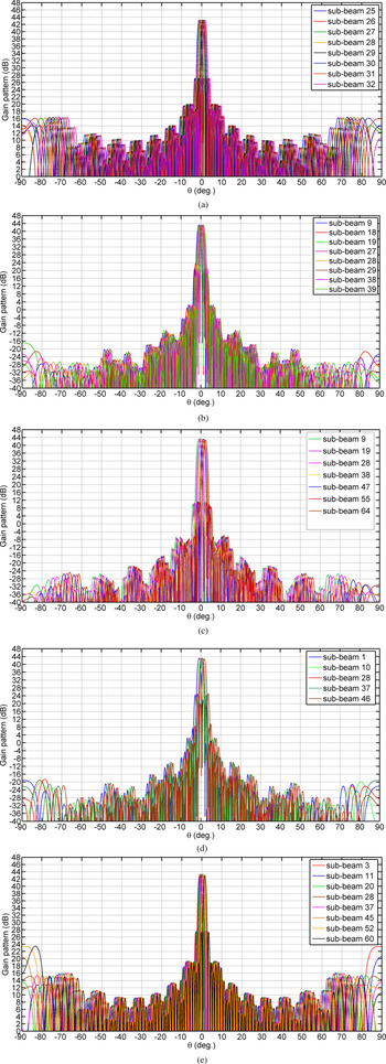
The gain patterns of the optimized multiple sub-beam array in the φ = 0°, φ = 22°, φ = 45°, φ = 67°, and φ = 90° constant planes are illustrated in Figs 11(a), (b), (c), (d), and (e), correspondingly. As illustrated in these figures, grating lobes have been eliminated in the visible region. It has been assumed that the coordinate origin is located at the center of sub-beam 28 (refer to Fig. 10). In Fig. 12, the sub-beams in the φ = 0° constant plane for the θ between −10° and 10° are presented. As can be inferred, the corresponding values of G EOC and crossover level are 42 dBi and 1 dB, respectively. The angular distance between the adjacent beams in the x direction agrees with the antenna requirements in Table 1 (third column). In this array, SLL has been decreased to −16 dB, which is lower compared to the value of −13 dB observed in the uniform excitation. This SLL improvement is the result of adding skirt elements and optimum non-uniform amplitude distribution.
Optimization results of the multiple sub-beam antenna, gain patterns versus θ in the: (a) φ = 0°, (b) φ = 22°, (c) φ = 45°, (d) φ = 67°, and (e) φ = 90° constant planes.

Gain patterns of the multiple sub-beam antenna versus θ in φ = 0° constant plane.

C/I versus θ in different φ planes of the desired spot are illustrated in Fig. 13. As depicted in this figure, the minimum amount of C/I in the spot domain is more than 8.5 dB and satisfies the requirement listed in Table 1. Three-dimensional (3D) gain pattern of the synthesized multiple sub-beam array is illustrated in Fig. 14. Design of a proper BFN for the optimized array antenna will be described in the section “Designing the block diagrams of BFN for multiple sub-beam array.”
C/I (dB) in the domain of spot 6.

3D gain pattern of the designed multiple sub-beam antenna (in dB).

Comparing a multiple sub-beam antenna with a conventional multiple beam antenna
In this sub-section, an array with conventional requirements of a multiple beam antenna (refer to Table 1) has been designed and optimized by means of the GA. The aim of this design is the array aperture size reduction using sub-beam concept. The results after GA optimization are listed in Table 2. The consequence is 36.7% reduction in aperture size and elements in the multiple sub-beam antenna. Figure 15(a) shows directivity pattern of the beams, which are located in the diagonal axis plane of the spots. Figure 15(b) illustrates C/I for different constant φ planes in spot 6. In this design, the coordinate origin has been located at the center of spot 6.
Optimization results of the multiple beam antenna: (a) gain patterns in the diagonal plane crossing beams 1, 6, 11, and 15 and (b) C/I (dB) in the domain of spot 6.

Full-wave simulation
The full-wave simulation resembles the radiation characteristics of an array in the praxis. For this reason, the planar array has been simulated in Ansoft HFSS, which is a full wave simulation environment. Due to the processor and memory constraints, only a 12 × 12 array has been simulated. This simulation takes the advantages of finite array domain decomposition method, which enables the processor to use the distributed memory. In this method, mutual coupling and edge effects of the array elements have been considered while reducing the modeling and simulation time.
The phases of the array elements for each beam have been calculated separately using the synthesis formulas in the section “Array synthesis concerning multiple sub-beam constraint,” and uploaded to the simulated model in HFSS. The simulation frequency and the patch radius are 3.64 GHz and 1.21 cm, respectively. For the substrate an RO4003 with 0.8 mm thickness has been chosen.
In the simulation, the number of beams, the element spacing in the x and y directions (dx and dy), the numbers of elements in each sub-array in the x and y directions (Nx and Ny), the numbers of sub-arrays in each row and column (Nsx and Nsy), and the number of skirt elements in each row and column (Nskx and Nsky) have been assumed to be 16, 0.5λ, 2, 4, and 4, respectively.
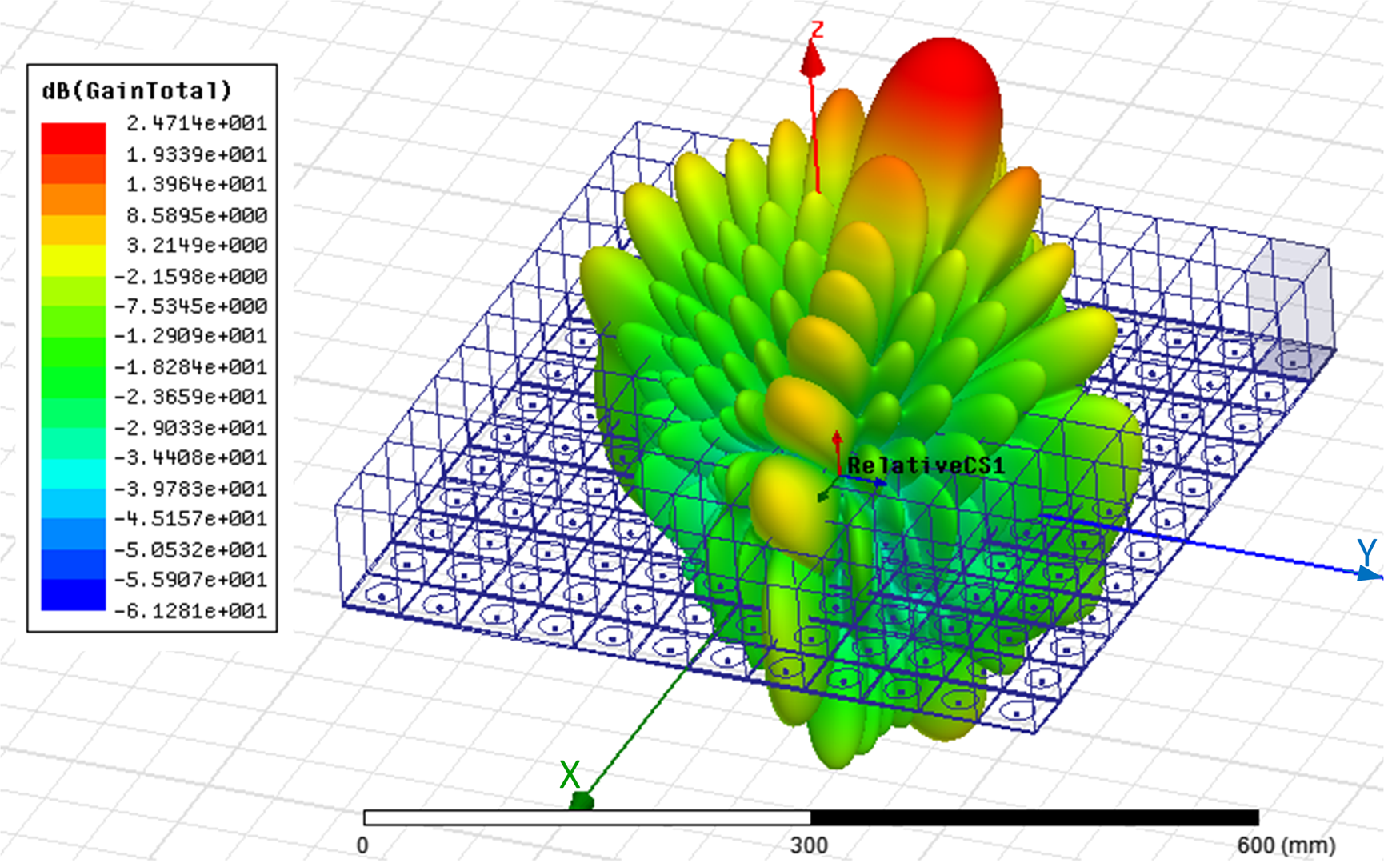
In Fig. 16, the total gain patterns of eight diagonal beams versus θ in the diagonal axis plane (φ = 45° constant plane) are demonstrated. In this figure, the analytical results of the AF calculations presented in the section “Array synthesis concerning multiple sub-beam constraint” have been compared with the full-wave simulation results. The analytical results have been plotted by using MATLAB. These results are in agreement with each other. The full-wave simulation results by HFSS verify the elimination of grating lobes in the visible region. The 3D radiation patterns of the first beam and the array model are illustrated in Fig. 17. The 3D radiation patterns of the other seven beams are similar to the first beam in SLL and grating lobe aspects.
HFSS and MATLAB simulation results of a 12 × 12 planar array with interleaved sub-arrays in φ = 45° constant plane, Px = Py = 8, Nsx = Nsy = 4, Nx = Ny = 2, Nskx = Nsky = 4, dx = dy = 0.5λ, Askrx = Asklx = Askry = Askly = 0.7.

Array model in HFSS and the radiation pattern of beam 1 with interleaved sub-arrays, Px = Py = 8, Nsx = Nsy = 4, Nx = Ny = 2, Nskx = Nsky = 4, dx = dy = 0.5λ, Askrx = Asklx = Askry = Askly = 0.7.
To illustrate the effects of interleaving sub-arrays in the grating lobe elimination, a planar array designed by tile sub-arraying technique has been simulated in HFSS. This array is similar to the array of Fig. 16 in the number of beams, number of array elements, and the angular distance between adjacent beams. The amplitude distribution of this array is unique. In Fig. 18, the simulation results of this array have been presented. As is seen, the grating lobes have been appeared in the visible region.
HFSS simulation results of a 12 × 12 planar array with tile sub-arrays, Px = Py = 8, Nsx = Nsy = 3, Nx = Ny = 4, dx = dy = 0.5λ.

Designing the block diagrams of BFN for multiple sub-beam array
Optimization results in Table 2 (third column) show that the number of sub-array elements is not equal to the number of beams. Consequently, the standard BM cannot be used to design the BFN. To design the BFN, the relations presented in the section “Devising the BFN” must be used.
As presented in (11), the extra phase shifts that must be applied to the right skirt elements are different for various beams. In the following paragraph, the extra phase shifts of the designed antenna array in the section “Array optimization concerning sub-beam concept” will be calculated. Optimization results showed that P x = 4N x, and N x is even. Therefore, the extra phase shifts which should be added to the right skirt elements in each row are calculated using (23):

Since P y = 4N y and N y = 2, $\Delta \varphi _{y_{right}}( c_y)$ can be calculated similarly.
As indicated in (23), for the first BG which consists of beams A and E, a phase shift of −π/4 must be added to the right skirt elements. For the second BG, a phase shift of −3π/4 must be added to the right skirt elements. Similar conditions hold for BG3 and BG4. The total number of BGs in the x direction using (11) is equal to M x. The corresponding in the y direction is denoted by M y = P y/N y. In this design, M x and M y are equal to 4.
Using (14)–(18), for P x = 8 and N x = 2, the excitation signals of the first and second elements of each sub-array, which are related to a right skirt element (in BFN1), have been obtained as follows:


Therefore, BFN1 consists of four 180° hybrids with sum-ports exciting the first element of the sub-arrays and the corresponding right skirt element. In addition, the difference-ports excite the second element of the sub-arrays. There are four BGs, which need four different $\Delta \varphi _{x\_right}$ for feeding the relevant right skirt element, as calculated in (23). In addition, two-way power dividers are used to provide the required signals for the right skirt elements, consistent with (9). BFN1 block for the designed array is illustrated in Fig. 19(a).
Block diagram of (a) BFN1, (b) BFN2, and (c) BFN3.

Using (19)–(20), the excitation signals of the first and second elements of the sub-array, which are related to the left skirt element (in BFN2), have been calculated in (26) and (27). The block diagram of BFN2 for the designed array is plotted in Fig. 19(b).


Since the calculated A skrx(k) and A sklx(k) in Table 2 are unique for all amounts of the k, all BFN1s have the same power division ratios. Using similar reasoning, all BFN2s which are designed for different sub-arrays are identical.
For feeding the core elements which are not connected to any skirt element, the feed network in Fig. 19(c) has been designed.
The operating frequency band of the optimized antenna as mentioned in the section “Array optimization concerning sub-beam concept” is C-band. The designed BFN can be practically implemented by planar microwave circuits. The BFN consists of 180° hybrids, phase shifters, crossovers, and power dividers, which are usually realized by microstrip technology. In addition, using microstrip technology, construction cost and size of the structure are lower compared to the other microwave structures similar to waveguides and substrate integrated waveguides. The array row- and column-feeds can be easily stacked and integrated to take the shape of a compact box for the antenna BFN.
The overall antenna system configuration is illustrated in Fig. 20. In the array aperture, the row elements which are fed by different types of BFNs are shown by different colors. Also, the column elements which are fed by different types of BFNs are indicated by different filling patterns.
Configuration of the designed antenna system.

As can be inferred from Fig. 20, each row is excited by a sheet that consists of 18 SABFNs, eight power dividers and some phase shifters to provide the required phase for each SABFN. As indicated in Fig. 20, input ports of the rows’ BFN sheets are fed by the columns’ BFN sheets. In this way, the required phase shifts between the rows have been provided.
The optimized multiple sub-beam antenna using interleaved sub-arraying technique has been compared with some other synthesizing methods. The comparison criteria in Table 3 are aperture size, BFN complexity, and SLL. The requirements for multiple beam antenna in Table 2 have been used for comparison purposes. As inferred from Table 3, the size of the proposed array with multiple sub-beams is intensively lower compared to other studies. In addition, BFNs which have been designed by other approaches are more complex than the proposed BFN in this paper.
Comparison between multiple beam array synthesis techniques

Conclusions
An array antenna with interleaved sub-arrays for generating multiple sub-beams in two dimensions was designed. A comprehensive example including some major technical requirements was presented. The main parameters of the array antenna were selected after an optimization process by means of the GA. Sub-arrays with interleaving elements must be excited with separate BFNs. Optimization results showed that the number of elements in each sub-array was not equal to the number of beams. Consequently, a novel BFN that consisted of three different types of BFNs with orthogonal beams and unequal number of beam ports and element ports was devised. In addition, the proposed BFN could satisfy the requirement of a very short angular distance between adjacent sub-beams. Gain patterns of the sub-beams and carrier to interference ratios in a spot domain are the parameters that were calculated. The gain patterns showed that the grating lobes were eliminated. Gain at the EOC for sub-beams was 42 dBi, and the crossover level was 1 dB. Using sub-beam concept and the flat patterns for the antenna, the array aperture size was decreased by 36.7%. In one of the spots, C/I in different points of the spot domain was calculated. In the worst case, C/I reached a value of 8.5 dB, and satisfied the antenna's requirement. As the decreased size of the payload did not degraded the C/I appreciably and led in all aspects to satisfactory results, the proposed method is suitable for multi-beam antenna design and implementation. Designed BFN and antenna array are currently under construction, and implementation results will be subject of future papers.
 Elham Sharifi Moghaddam is pursuing her Ph.D. degree in communication engineering at the K. N. Toosi University of Technology, Tehran, Iran. Her research interests are antennas, RF and microwave components, and satellite communication.
 Arash Ahmadi received his B.Sc. degree in communication engineering from the K. N. Toosi University of Technology, Tehran, Iran, in 2000, his M.Sc. degree in communication engineering from the Sharif University of Technology in 2003, and received his Ph.D. degree in communication engineering from the Sharif University of Technology, Tehran, Iran, in 2009. He is currently assistant professor at the K. N. Toosi University of Technology. His research interests are wideband power amplifiers and microwave passive components.