I. INTRODUCTION
Wireless communication standards are continuously evolving to achieve greater spectral efficiency and higher data-rates. Contemporary standards such as the long-term evolution (LTE), LTE-advanced, and WiMAX have adopted orthogonal frequency-division multiplexing (OFDM) with a large number of sub-carriers and high-order constellations in order to achieve this target. This comes at the expense of wider channel allocations and high peak-to-average power ratio (PAPR) signals which reduce the average power efficiency of the transmitter. Additionally, very high linearity is required by both the transmitter and receiver. Meeting the linearity requirement represents the first challenge for sub-systems such as the power amplifier (PA). The designer's toolkit to meet this requirement includes techniques such as feed-back, feed-forward, pre-distortion, and more recently digital pre-distortion [Reference Cripps1].
At the same time the low-power consumption required from the transmitter, especially in the case of mobile devices, makes the situation even more challenging. The PA has attracted a lot of attention as one of the most power hungry component in the transmitter chain. To enhance its efficiency, and consequently that of the transmitter, under high PAPR signals a number of techniques have been investigated and developed over the years. In principle, they can be categorized under supply modulation – envelope tracking (ET) and envelope elimination and restoration (EER) – load-modulation (Doherty and dynamic LM (DLM)) and linear amplification with non-linear components [Reference Cripps1]. As far as wideband amplification is concerned, supply modulation and DLM have been shown to be the most promising [Reference Kenle and Peroulis2, Reference Moon, Son, Lee and Bumman3].
The system efficiency in supply modulation systems is mainly limited by the supply modulator, especially under large envelope bandwidths. Consequently, even though DLM cannot provide the same level of efficiency enhancement as supply modulation [Reference Nemati4] the fact that the tunable matching network requires negligible tuning power, as well as, the lower system complexity makes it a very appealing technique for such wideband applications. For the implementation of the LM network varactor and pin diodes, FETs, and MEMS have been proposed [Reference Raab5–Reference Arnous8], depending on the target output power levels and frequency. Recently, an 86 W peak output power DLM PA at the microwave band was demonstrated using SiC varactor diodes, showing promising results also for high-power implementations of the technique [Reference Andersson9].
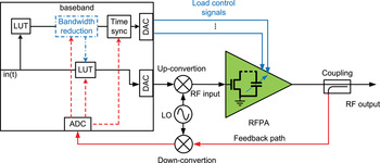
A simplified architecture for a DLM transmitter is given in Fig. 1. The radiofrequency (RF) amplifier in such an architecture becomes a multi-input (at least two) one output system, with one RF and at least one control input that modulates the load of the amplifier. Multiple inputs may be used if more than one tunable elements are employed. The tunable elements can be integrated with the output matching network of the amplifier or connected externally [Reference Tehrani, Nemati, Haiying, Eriksson and Fager10], with the former being more popular for minimizing size and the associated losses. In the baseband processor, some additional processing is also required. From the time-domain signal and using two look-up tables (or other techniques), the appropriate input drive level and load control signals are generated for maximizing the efficiency of the transmitter. The load control signal can be optionally further processed to reduce its bandwidth, while appropriately adapting the input drive [Reference Mimis and Watkins11, Reference Cao, Fager, Khan, Tehrani and Eriksson12]. Finally, the various signals have to be time aligned before fed to the amplifier.
Simplified generic dynamically load-modulated transmitter architecture.

This final step of time aligning the RF input and the load control signal (or the envelope signal in supply modulation architectures) is important for both DLM architectures and supply modulation [Reference Raab13–Reference Rudolph15]. Even small time mismatch has been shown to lead to severe distortion. This is a well-studied subject for supply modulation architectures but little attention has been given to it in the context of DLM. In [Reference Tehrani, Nemati, Haiying, Eriksson and Fager10] the time alignment was performed manually for a DLM amplifier. A time alignment algorithm based on cross-correlation of the RF input and the envelope signal with use of sinc interpolation for sub-sample accuracy was proposed by Cao et al. [Reference Cao, Tehrani, Nemati, Fager, Eriksson and Zirath14] and was further used before applying pre-distortion linearization in [Reference Cao, Nemati, Tehrani, Eriksson, Grahn and Fager7].
This study sets to expand previously conducted work [Reference Mimis and Watkins16] which investigated the impact of time misalignment between the two paths in DLM PA architectures first in theory, with the help of a simple transistor model, and then in practice using a 10 W dynamically load-modulated LDMOS RF PA. For the theoretical and practical analysis, output power, efficiency, and adjacent channel leakage power ratio (ACLR) are considered.
The paper is organized as follows: Section II introduces the amplifier model, the analysis methodology, and results. Section III describes the practical implementation, the measurement setup, and discusses the experimental results with respect to the expected behavior. Section IV presents the RF PA performance under an LTE signal and compares it with other state-of-the-art implementations, before concluding the paper in Section V.
II. DYNAMIC LM MISALIGNMENT ANALYSIS
To investigate the effect of the time misalignment between the RF input and load control signal a simple system model is used, which is described next. The model is expected to associate the output power, phase shift, and efficiency of the amplifier with the input drive level and the value of the load at each instance. First, the model is introduced before deriving the optimal input and load conditions for maximizing the amplifier efficiency. The optimal input and load control signals are generated for a variety of multi-tone signals and shifted with respect to each other while calculating the system's efficiency, output power and linearity.
A) Amplifier model
For the model a perfectly transconductive device is assumed with hard saturation characteristics, biased in class-B mode and with no “knee” voltage. In other words, the device exhibits a perfect half-wave rectified drain current with an amplitude proportional to the input voltage. The well-known fundamental (i d ) and DC (i DC ) components of such a waveform are given by (1) and (2), respectively. Maximum drain current amplitude is denoted as I max , while input drive as β. Both variables are normalized. Alternative drain current waveforms can also be used to model the device's turn-on and saturation characteristics more accurately [Reference Mimis, Bensmida, Morris and McGeehan17, Reference Colantonio, Giannini, Leuzzi and Limiti18].
 $$i_d = \beta \displaystyle{{I_{max}} \over 2},$$
 $$i_{DC} = \beta \displaystyle{{I_{max}} \over \pi}.$$
The introduced phase shift (Φ out ), output voltage swing (V out ) and output power (P out ) of the amplifier are given by (3)–(5), respectively, with R L denoting the fundamental load presented to the device and V DC the supply voltage.
α and n are constants. All harmonics are assumed to be shorted and so V out is only a function of the output fundamental current and load. V DC and R L are normalized, with the later normalized to optimum class-B bias load at maximum output level. The phase response of the system is modeled by a static phase shift (ϕ MN ) as the amplifier approaches compression. Closer to and within the compression region an increasing phase shift, proportional to the compression level is introduced on top of the static shift.
Moreover, V out is restricted to not exceed V DC in amplitude so that a maximum drain swing between 0 and 2V DC is allowed, to model compression and remove unrealistic efficiencies above the theoretical maximum. The efficiency of the model is given by (6) which due to the class-B bias and absence of “knee” voltage reaches a maximum of 78.5%, as expected. Analysis under different bias conditions can also be performed by appropriately adapting (1)–(6) [Reference Mimis, Bensmida, Morris and McGeehan17, Reference Colantonio, Giannini, Leuzzi and Limiti18].
 $$\Phi _{out} = \left\{ {\matrix{ {\phi _{MN},} & {V_{out} \lt 0.9V_{DC},} \cr {\alpha (V_{out} - V_{DC} )^n + \phi _{MN},} & {{\rm otherwise,}} \cr}} \right.$$
 $$V_{out} = \left\{ {\matrix{ {i_d R_L,} & {V_{out} \lt V_{DC},} \cr {V_{DC},} & {{\rm otherwise,}} \cr}} \right.$$
 $$P_{out} = \displaystyle{{V_{out}^2 R_L} \over 2},$$
 $$\eta = \displaystyle{{P_{out}} \over {P_{DC}}} = \displaystyle{{V_{out}^2 R_L} \over {2V_{DC} i_{DC}}}.$$
So far, the fundamental load has been assumed to be static, i.e. no LM is applied. For analyzing the DLM case, R
L
is defined as a function of input drive β and restricted by minimum and maximum values to account for the finite LM ratio that can be achieved in practical DLM amplifiers. The optimal value of the fundamental load as a function of β denoted by
 $R_{l_{opt}} $
is given in (7) with a tunable ratio of
 $R_{DLM} = R_{l_{max}} /R_L $
.
 $R_{l_{max}} $
denotes the maximum achievable fundamental load. For the rest of the analysis R
DLM
is set to 4. In (3) α and n are set to 150 and 3, respectively. Moreover, Φ
out
also becomes a function of the load by modifying (3) through ϕ
MN
which is now given by (8), in which ϕ
0 and γ are constants.
 $$R_{l_{opt}} = \left\{ {\matrix{ {\displaystyle{{V_{DC}} \over {\beta (I_{max} /2)}},} & {R_{l_{opt}} \lt R_{l_{max}},} \cr {R_{l_{max}},} & {{\rm otherwise,}} \cr}} \right.$$
 $$\phi _{MN} = \phi _0 + \gamma \left( {\displaystyle{{R_{l_{opt}}} \over {R_{l_{max}}}}} \right)^3.$$
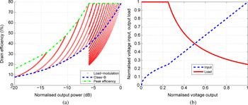
Using the described model, the performance plotted in Fig. 2(a) is acquired with the typical class-B performance also plotted (dashed line). By adapting the load with a ratio of R DLM = 4 and appropriate input drive, maximum efficiency can be maintained up to 6 dB output power back-off and is 50% at the 10 dB back-off. The efficiency can be enhanced for larger back-off if a higher LM ratio can be realized. By definition the model only exhibits drain voltage saturation.
Performance of the simple amplifier model.

B) Drive signals and methodology
With the use of (5)–(7) the optimum input drive and output load can be calculated and are plotted over output in Fig. 2(b). These two drive functions track the maximum efficiency trajectory over output power. In Fig. 2(a), the dashed-dot line represents the highest efficiency points and is recreated using the drive functions of Fig. 2(b).
The two drive functions will be used to generate the optimal load and input drive for the desired amplified signal. Multi-tone signals with different properties will be used as the inputs of the model, while observing how each property affects the sensitivity of the system to time mismatch. Plots of efficiency, output power and ACLR over delay will be given in each case.
C) Results and discussion
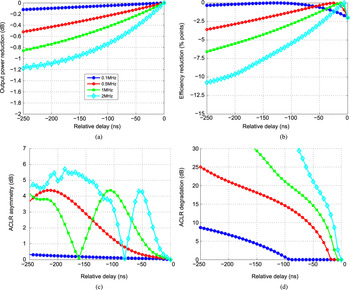
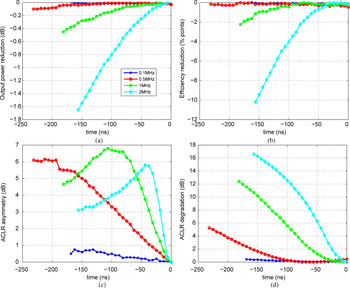
For all cases a sampling rate of 160 MSps is assumed throughout and is chosen for consistency with the experimental measurements performed later. In the first case, the number of input tones is fixed to 5 and the modulation bandwidth is varied from 100 kHz to 2 MHz. The delay is swept between −250 and 0 ns and the results are plotted in Fig. 3. More specifically, output power, efficiency ACLR and ACLR asymmetry are plotted in Figs 3(a)–3(d). Only negative delay is plotted in the graphs as the results are symmetrical about 0 ns delay because the input signal envelopes are even functions.
Estimated performance under 5-tone input with variable channel bandwidth over swept path delay.

As expected, increasing the modulation bandwidth and consequently the frequency bandwidth of the control signal has a negative impact on the misalignment sensitivity of the system. The rate of performance degradation varies drastically with the signals’ bandwidth. Moreover, minimum distortion does not coincide with maximum efficiency as has already been observed [Reference Mimis and Watkins16]. By examining the estimated performance under the 2 MHz 5-tone signal with a 50 ns time delay, output power and efficiency degrade only by 0.4 dB and 2.5% points, respectively. On the other hand, average ACLR and especially the asymmetry are expected to suffer significantly.
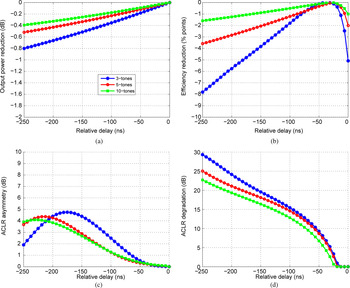
In a second test case, a 500 kHz modulation bandwidth is used with 3-, 5-, and 10-tones of equal amplitude and starting phase spread over the channel bandwidth. The output power, efficiency, ACLR and asymmetry for all the multi-tone signals over delay are plotted in Fig. 4. As expected the maximum linearity is achieved when the two paths are perfectly synchronized. As observed in the first test case, peak efficiency does not coincide with minimum distortion and peak output power. Moreover, the most sensitive performance parameter is linearity and especially ACLR asymmetry.
Estimated performance under 500 KHz channel bandwidth input signal with variable number of tones over swept path delay.

An additional, counter-intuitive result is that for a given channel bandwidth, of 500 kHz in this case, the sensitivity of the system to time misalignment is inversely related to the number of tones used. In other words, these results seems to indicate that under a multi-tone or OFDM type of signal where a larger number of tones/sub-carriers reside within a channel of certain bandwidth leads to a more robust system against time misalignment. For a mismatch of −150 ns under the 3-tone signal and ACLR asymmetry of above 4 dB is predicted, whereas for the 5- and 10-tones it is below 3 dB.
Using the model different ratios R DLM were simulated both above and below 4. Although the results are not included here, they indicate that for a given signal, changing the LM ratio will also affect its sensitivity to time misalignment. This can be thought of as follows: utilizing LM for a larger proportion of the signal cycle leads to enhanced efficiency – through the LM effect – but also makes the architecture more sensitive to time delay. On the other hand, restricting the LM phenomena lowers the average efficiency but the system is more resilient to path misalignment.
These effects have been previously observed in studies of EER and ET systems [Reference Rautio and Rahkonen19], where ET would be the equivalent of a DLM system with lower LM ratio. In other words, a DLM amplifier with infinite LM ratio where the load is modulated during the whole RF signal cycle behaves similar to an EER system. On the other hand, a finite ratio DLM amplifier would be the equivalent to an ET system with the different LM ratios corresponding to the different envelope shaping functions [Reference Moon, Son, Lee and Bumman3].
III. MEASUREMENT RESULTS
To verify the findings experimentally, a dynamically load-modulated RF power amplifier was built and measured. After its static characterization, the optimal RF input and varactor control signals were extracted. The amplifier was then driven with various multi-tone signals and while the relative delay between the input and control signal was swept, efficiency, output power and spectral regrowth were measured. First, the amplifier design is described, before introducing the measurement setup and procedure. Then the experimental results are presented followed by a discussion and comparison with the expected behavior.
A) Dynamic load-modulated prototype
The amplifier was designed around the NXP BLF6G21-10G, 10 W LDMOS FET transistor for a target frequency of 900 MHz. The large-signal device model was available in NI AWR Microwave Office and was used. First, the transistor was stabilized under Class-B bias before performing source- and load-pull simulations up to the second harmonic. Based on the load-pull simulations the fundamental termination trajectory for optimal efficiency at various output power levels was extracted and used to design the output tunable matching network.
One of the major challenges in DLM PAs is the loss of the output matching network due to the finite Q factor of the tunable elements, which is a function of the frequency of operation and equivalent series or parallel capacitance and resistance. This necessitates the reduction of the number of used tunable elements. In this design, an array of 4 × 2 varactor elements was implemented, connected in anti-series to improve linearity. The varactors were the Aeroflex MTV4060-03 cased in an epoxy encapsulated ceramic package (CS19). These devices have a tunable range of 1–8 pF under a bias of 0–60 V and high Q of above 100 at the frequency of interest.
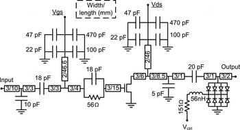
The DC bias to the transistor was provided using λ/4 lines at the gate and the drain. Moreover, at the gate a parallel RC circuit was used to achieve unconditional stability. This is particularly important for load-modulated PAs as the impedance environment will vary during operation. Finally, the output tunable matching network was designed with distributed and lumped elements. A schematic of the final design is shown in Fig. 5.
Simplified schematic of the dynamically load-modulated RF PA prototype.

To control the tunable matching network, the varactor driver is required to produce large voltage swings at high speed. Previous work [Reference Andersson6] used high-power hybrid circuits which have limited bandwidth, and due to their high-power nature consume significantly greater current than required to drive the varactors. High-speed, low-power commercial operational amplifiers are available, but their output voltage swing is limited due to their fabrication geometry. In this work, an amplifier based on a symmetrical current mirror which can produce a large output voltage swing at moderate bandwidth [Reference Watkins20] is used. The driver was modified to produce a voltage swing of 53 V peak-to-peak at a small signal bandwidth of 6.5 MHz. When reproducing a 1.4 MHz LTE control signal the NMSE was −32.1 and −28.2 dB with a 3 MHz LTE signal.
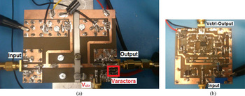
The amplifier and varactor driver circuit were fabricated on the low-cost, standard FR4 substrate. A photograph of the complete DLM amplifier and the varactor driver is shown in Figs 6(a) and 6(b), respectively. Board sizes measure to 7.5 × 6 cm2 for the PA and 5 × 5 cm2 for the varactor driver.
Photograph of dynamic load-modulated PA and varactor driver circuit.

B) Measurement setup
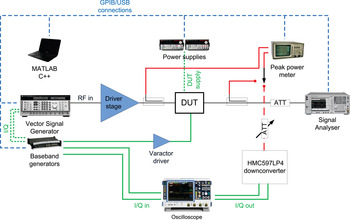
The measurement setup used for the static and modulated signal measurements is depicted in Fig. 7. A Lecroy arbitrary waveform generator (ARBstudio) is used to generate the baseband I/Q and varactor control signals. The I/Q signals modulate an RF carrier using an Agilent 8780A Vector Signal Generator and are fed to the DLM amplifier through a driver amplifier (Mini-circuit ZHL-30W-252-S+). The varactor control signal is amplified by the varactor driver to provide the needed voltage swing and its output is sampled using an R&S RTO oscilloscope. The output power of the amplifier and ACLR are measured using Agilent's E4440A Spectrum Analyzer. Input power is measured using an HP8991 peak power meter. The PA bias levels and DC current consumption are set and monitored using two Keithley power supplies. Finally, part of the output signal is coupled, attenuated and fed into a Hittite HMC597LP4 IC for down-conversion. The down-converted I/Q signals are also captured using the oscilloscope.
Overview of the measurement setup.

All the instruments are controlled remotely and the measurements are collected for post-processing using Matlab. Moreover, the instruments are triggered by a common trigger and use a common 10 MHz reference. The signal generator has a maximum sampling rate of 250 MSps, which also defines the relative delay compensation accuracy if a per sample synchronization is implemented. The multiple outputs of the signal generator can be delayed with respect to each other on a per sample resolution and this capability is used to intentionally misalign the RF input and varactor control signal.
C) Static characterization and control signal extraction
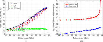
The amplifier was first characterized under continuous wave (CW) excitation for various input drive levels and varactor bias while driven up to its 3 dB compression point. Also, a frequency sweep was performed and an operating frequency of 930 MHz was chosen as optimal. The measured drain efficiency, power-added efficiency (PAE) and gain are plotted over output power in Fig. 8(a). The amplifier delivers 41.2 dBm peak output power with 76% PAE at the 3 dB compression point and through LM maintains it close to 40% at 10 dB back-off. The linear gain of the device is about 17 dB under a supply voltage of 26 V.
Static measurements of DLM PA at 930 MHz.

The input amplitude and varactor bias levels that correspond to maximum PAE at each output level – as indicated in Fig. 8(a) by the dashed line – were extracted and are shown in Fig. 8(b). It has to be noted that the load control signal may show expanded frequency content compared with the original signal by 3–4 times [Reference Tehrani, Nemati, Haiying, Eriksson and Fager10, Reference Mimis and Watkins11]. For that reason the varactor driver was characterized and its bandwidth was determined as 6.5 MHz. This had to be considered for the test signals used as no additional filtering is performed on the load control signal.
D) Multi-tone signal measurements
The RF input power was set in accordance with the static characterization and was kept constant during the course of the measurements. The signals’ time alignment was swept with a time step of 6.25 ns. The sampling rate was set to 160 MSps which was considered sufficient and was in-line with the analysis, even though the measurement setup allowed for 250 MSps. Moreover, only results of the negative relative time delay are shown as was done for the analysis.
Initially, the RF PA was driven with 5-tone input signals with channel bandwidths between 0.1 and 2 MHz, all with a 4.7 dB PAPR. The tones were equally spaced within the channel. Figure 9 shows the measured output power (9a), PAE (9b), ACLR asymmetry (9c), and average ACLR (9d) degradation over relative time delay. All the plotted results are normalized to either the maximum measured value, for output power and efficiency or minimum, for ACLR results.
DLM PA performance under 5-tone input with variable channel bandwidth and swept path delay.

From the results, there is a clear trend of higher output power, efficiency, and improved linearity toward the appropriately time aligned case. The rate at which efficiency, output power, and linearity degrades, depend on the channel bandwidth. An important point to note is that even for a small 25 ns misalignment where efficiency, output power, and average ACLR do not show much degraded characteristics, ACLR asymmetry for the 2 MHz 5-tone signal is very high, above 4 dB.
Moreover, the RF PA is measured under multi-tone signals with various numbers of tones, spread over 500 KHz. The signals are 3-, 5-, and 10-tone signals with 4.8, 7, and 10 dB PAPR, respectively. The results are plotted in Fig. 10. In this case, it is only ACLR asymmetry that shows significant dependence on the time delay. Even average ACLR shows < 1 dB variation for up to 100 ns miss-estimation. More importantly, the rate at which ACLR asymmetry increases with time delay differs between the signals. There is a trend for the RF PA to show increased sensitivity to time delay when driven with lower PAPR input signals as LM takes place for larger part of the signal cycle.
DLM PA performance under 500 KHz channel bandwidth input signal with variable number of tones and swept path delay.

E) Discussion
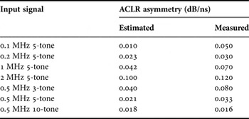
The analysis succeeded in predicting most of the observed effects under delay mismatch with reasonable accuracy, given the simplicity of the chosen model. In the first test case of increasing channel bandwidth, most of the effects were predicted by the analysis, including the non-coincidence of peak efficiency, peak output power, and minimum distortion. Moreover, the sensitivity of the system on ACLR asymmetry and the different gradients of performance degradation are clearly predicted by the model. In quantitative terms under the 2 MHz 5-tone signal the model predicts, roughly, a degradation of output power by 0.1 dB/ns, efficiency by 0.05% point/ns, ACLR by 0.4 dB/ns and asymmetry of 0.1 dB/ns. From the measurements we find that output power degrades by 0.012 dB/ns, efficiency by 0.09% points/ns, ACLR 0.11 dB/ns, and asymmetry by 0.12 dB/ns. These numbers were extracted by linear fitting in the region around perfect time alignment. ACLR is not predicted accurately and this can be accounted mainly to the hard saturation characteristic of the model.
For the case of fixed channel bandwidth and variable number of tones the model predicts a less sensitive system to time misalignment, for an increased number of tones. This trend is also present in the measurements for the ACLR and asymmetry, but is not as profound for the output power and efficiency. The quantitative discrepancies found between the model and measurements can be tolerated in favor of simplicity. All the results are consistent with previously observed behavior of a low-power GaAs DLM amplifier [Reference Mimis and Watkins16]. It can be concluded that applying a delay estimation approach that minimizes ACLR asymmetry is critical and could enable the use of simple, memoryless digital pre-distortion algorithms for the linearization of DLM PAs [Reference Bensmida21]. The estimated and measured degradation of ACLR asymmetry, as the most sensitive metric, per ns of time delay is summarized in Table 1. It is clear that the delay estimation accuracy requirement increases with channel bandwidth and lower PAPR and in some cases could also justify the use of sub-sample estimation techniques [Reference Cao, Tehrani, Nemati, Fager, Eriksson and Zirath14].
Summary of estimated and measured ACLR asymmetry per ns of delay.

IV LTE SIGNAL MEASUREMENTS
Measurements with a 1.4 MHz LTE signal were performed next. Using NI AWR visual system simulator (VSS) software a 16-QAM 1.4 MHz with 7.8 dB PAPR was generated. The RF input and load control signals were calculated using the static functions as before and applied to the DLM amplifier. Delay estimation between the inputs was calculated purely for minimization of ACLR asymmetry, as was indicated by the analysis and measurements of multi-tone signals. The previously described measurement setup was used again for these measurements. A simple memoryless, fifth order, polynomial pre-distortion was applied to improve the linearity of the amplifier. The coefficients were calculated based on a characterization under a drain supply of 26 V.
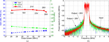
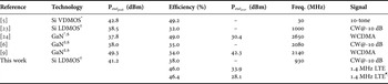
Measured efficiency, gain, and ACLR versus output power are plotted in Fig. 11 for the LTE signal under a few drain supply voltages between 14 and 28 V. As evident, LM is still effective at different drain bias conditions [Reference Mimis and Watkins22]. In all cases, the same input drive functions – and pre-distortion coefficients – were used and only input power level and supply voltage were scaled. The output spectrum is also given in Fig. 11(b) for the LTE signal under the 26 and 28 V supplies. Finally, the measured efficiency, output power and ACLR are given in Table 2 and compared with the state-of-the-art. The presented amplifier compares well to published results in the literature and is based solely on commercially available, packaged components.
DLM PA measurements under a 1.4 MHz LTE signal at a center frequency of 930 MHz.

Comparison of state-of-the-art DLM amplifiers.

* FETs as tunable elements.
† Si abrupt junction varactors.
‡ SiC varactors.
§ Bared die.
¶ Lower supply voltage.
V. CONCLUSIONS
The effect of time misalignment between the RF input and load control signal in load-modulated PAs was theoretically and experimentally investigated using an LDMOS DLM amplifier operating at 930 MHz. Analysis and measurements under multi-tone signals showed, as expected, that proper alignment of the signals is crucial – but is shown especially important for minimizing ACLR asymmetry. The importance of signal synchronization becomes more profound as channel bandwidths grow, while it also depends on the statistics of the amplified signal. Finally, the DLM RFPA was measured under a 7.8 dB PAPR, 1.4 MHz LTE signal achieving 46% at 33.9 dBm output power. It was shown that good efficiency and linearity can be maintained over output power simply by scaling the input power and drain supply.
ACKNOWLEDGEMENTS
The authors would like to thank all at Toshiba's Telecommunications Research Laboratory for their support in this work. Also special thanks go to Dr. T. Hone of the Centre of High Frequency Engineering, Cardiff University, UK for the valuable discussions.
 K. Mimis received M.Sc. in Advanced Microelectronic Engineering and Ph.D. degrees on the topic of High Efficiency and Broadband Power Amplifiers from the University of Bristol, Bristol, UK, in 2008 and 2013, respectively. Since 2012 he has been with Toshiba Research Europe Limited, Bristol, UK. His research interests include high efficiency, broadband power amplifier design, linearization, and efficiency enhancement techniques.
 G. T. Watkins MIET MEuMA received the M. Eng. degree in Electrical and Electronic Engineering in 2000 from the University of Bristol and a Ph.D. from the same institution in 2003 on the topic of Wideband Feedforward Amplifiers for Software defined Radios. From 2003 to 2004, he was a technical consultant for Detica Information Intelligence before joining the University of Bristol as a research associate. Since 2008 he has been with Toshiba Research Europe Limited where he is currently a Principal Research Engineer. His research interests include linear power amplifiers, high efficiency system architectures, analog circuitry, high-speed power switching architectures, and wideband RF structures.