I. INTRODUCTION
In the face of the current increasingly serious problem of oil and gas pipeline corrosion, the major corrosion prevention methods for oil and gas pipelines are optimizations of their matrix material and contact environment. Anticorrosion principle is to isolate metal pipe from corrosive environments, such as the use of anticorrosion coatings and electrochemical protection from corrosion mechanism. At present, there are a variety of techniques for metal–matrix ceramic coating pipes, for example, self-propagating high-temperature synthesis, thermal spraying, laser cladding ceramic coating, and chemical reaction technology. Cobalt-based alloy coatings are widely used in wear-related application due to their excellent strength, corrosion resistance, and hardness over a wide temperature range. Reference Farnia, Ghaini, Ocelik and De Hosson1,Reference Liu and Wang2 The Co–Cr–W alloy, as one of the wear-resistant cobalt-based alloy, is versatile material and well-suited for a wide range of hardfacing application. Microstructurally, the Co–Cr–W alloy is reinforced by the carbides or intermetallics in the cobalt base solid solution. Reference Lin and Chen3 Although adding a large amount of carbides and intermetallics can effectively enhance the hardness and wear resistance, the comprehensive mechanical properties of Co–Cr–W alloy depend on the size, morphology, and distribution of carbides. The dispersive distribution of fine carbide particles in the Co-base solution is favorable for improving its mechanical performances. Laser cladding, as an advanced surface modification technology, is usually used for the preparation of metallurgical well-bonded Co-base coatings. Nevertheless, during solidification of laser melting Co-base alloy, the carbides tend to precipitate along grain boundary and form coarse network structure with several micrometers. Reference Farnia, Ghaini, Ocelik and De Hosson1,Reference Yan, Wang, Xu, Wang and Huang4,Reference Zielinski, Smolenska, Serbinski, Konczewicz and Klimpel5 The brittle network carbides thus very easily lead to crack and exfoliation in the service process, which seriously limit the lifetime of Co–Cr–W coating. However, it is difficult to transform the network carbides to uniform dispersion and refine it to nanometer size by subsequent heat treating or other conventional methods.
Recently, much attention has been paid to surface nanocrystallization by severe plastic deformation (SPD) to enhance the mechanical performances of metallic materials. Various surface SPD methods have been developed by crushing the coarse grain into ultrafine grain, such as surface mechanical attrition treatment, Reference Samih, Beausir, Bolle and Grosdidier6 air blast shot peening, Reference Unal and Varol7 surface mechanical grinding treatment, Reference Li, Tao and Lu8 and surface sliding friction. Reference Zhang, Zhang, Niu, Chen, Wang, Xiao, Chen, Yu, Yuan and Bai9 Nevertheless, above surface SPD means suffer from low microstructural uniformity and processing efficiency. Compared with other surface SPD process, friction stir processing (FSP), which is invented by drawing from friction stir welding (FSW), can produce nanograin uniformly and efficiently. Reference Chen, Fujii, Tsumura, Kitagawa, Nakata, Ikeuchi, Matsubayashi, Michishita, Fujiya and Katoh10,Reference Grewal, Arora, Singh and Agrawal11 The selected zone of workpiece can be strongly deformed by a rotary tool, which is inserted into the workpiece. After FSP, the original coarse grain in the stirred zone can be transformed into ultrafine or nanograin with excellent strength and hardness. Reference Escobar, Velasquez, Santos, Ramirez and Lopez12 Previous literature reported the production of nanostructured materials by FSP, such as soft metals Al alloys, Reference Khorrami, Kazeminezhad and Kokabi13 Mg alloy, Reference Yuan, Panigrahi and Mishra14 Cu alloy, Reference Mukherjee and Ghosh15 laser clad Fe-base alloy, Reference Hajian, Abdollah-zadeh, Rezaei-Nejad, Assadi, Hadavi, Chung and Shokouhimehr16–Reference Morisada, Fujii, Mizuno, Abe, Nagaoka and Fukusumi19 Co–Cr–Ni–Mo laser-clad alloy, Reference Li, Yuan and Qiu20,Reference Li, Li, Liang, Ji and Yuan21 and Co–Cr–Fe laser clad alloy. Reference Li, Yuan, Qiu, Zhou and Li22 The laser clad Co–Cr–W has different phase compositions, microstructures, and properties from Co–Cr–Ni and Co–Cr–Fe alloys, thus FSP on laser clad Co–Cr–W surface layer may result in different results. Literature on the microstructural modification of laser clad Co–Cr–W alloy by FSP is little. Moreover, the interface evolution between laser coating and substrate after FSP has not been researched in previous studies.
In this study, the FSP was used to modify the laser clad Co–Cr–W alloy layer so as to crush the network coarse carbides of Co–Cr–W alloy to dispersive particles with nanometer size. The nanostructure formation, microstructural evolution, interface bonding, hardness, and wear properties were characterized and the corresponding mechanisms were illuminated to improve the mechanical performances and enhance their applicable fields.
II. EXPERIMENTAL PROCEDURE
A. Laser cladding of Co–Cr–W powder
The nominal chemical compositions (wt%) of the gas atomized Co–Cr–W alloy powder were C: 1.75, Cr: 15.01, Fe: 11.12, Ni: 10.05, W: 15.58, and Co in balance. The cladding substrate was on A3 steel with a dimension of 50 mm × 70 mm × 10 mm, in which the surface was ground using a 400 μm grit paper and was sand-blasted to decrease surface reflectivity before laser cladding. Then, the Co–Cr–W alloy powder was pasted onto the A3 steel surface. The thickness of the paste was controlled in the range of 1.0–1.5 mm. The laser cladding system was equipped with a 5 kW pulsed CO2 laser (λ = 10.06 μm) and a 3-axesnumerically controlled working station. During the laser cladding process, a Gaussian pulse laser with a stable circular spot was applied and the laser beam was protected with Ar gas. The spot size of the laser beam was approximately 4 mm on steel substrate. The laser cladding was protected by shielding Ar gas with a flow rate of 25 L/min. The dilution ratio was below 10%. The laser clad parameters were: 2 kW laser power, 5 mm/s scanning speed , and 30% overlapping ratio.
B. FSP on the laser-clad Co–Cr–W layer
After the laser cladding Co–Cr–W coating on A3 steel, the as-prepared coating was modified by FSP. One disadvantage concerning the FSP of Co-base alloy is the tool wears due to the high hardness, wear resistance, and high melting point of Co–Cr–Fe alloy during FSP. Thus, the WC–Co hard metal was selected as a FSP tool material with a diameter of 12 mm without a probe. The FSP rotation speed was 600–1500 rpm with a travel speed of 10 mm/min. The tool was tilted 3° toward the backside with respect to the surface normal during FSP.
C. Evaluation of the laser clad and laser-FSP Co–Cr–W layer
Phase identification of laser cladding and laser-FSP specimens was performed by D/max2500pc x-ray diffraction (XRD; Rigaku Corporation, Tokyo, Japan) with Cu Kα radiation (k = 0.154 nm). Samples for metallographic examinations from cross-section were cut, ground, and polished according to the standard procedures and etched with a solution consisting of H2O2 (10 mL), HCl (16 mL), and methanol (24 mL) for 10–30 s. The microstructure of cross-section of the FSP samples was observed by scanning electron microscopy (SEM, Nova Nano SEM 230, FEI Corporation, Hillsboro, OR) equipped with an energy-dispersive spectrum (EDS). The EDS quantitative analysis was calibrated by Z absorption fluorescence correction (ZAF). The microstructures of the laser cladding samples and laser-FSP samples were observed by integration of focused ion beam (FIB) and transmission electron microscopy (TEM, JEOL-2100F, JEOL Corporation, Tokyo, Japan) operating at 200 kV, and high-resolution transmission electron microscopy (HRTEM) with selected area electron diffraction (SAED) pattern.
Microhardnesses of Co–Cr–W layers were tested by a micro-vickers hardness tester with a load of 300 g for 10 s. The wear resistances of surface layers were measured by a UMT-2MT tribo-meter with ball-on-disk configuration, without lubrication. The ball material was a quenched chromium steel with a Rockwell hardness of 60–63 and a diameter of 9.5 mm. The disk was vertically fixed and the ball could be reciprocally sliding on the disk. The wear tests were performed at room temperature with a fixed load of 5N. After the wear experiments, the wear morphologies were observed by SEM.
III. RESULTS AND DISCUSSION
A. Microstructure of laser cladding Co–Cr–W alloy
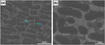
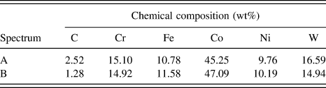
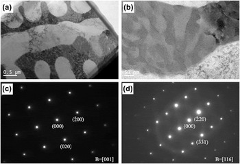
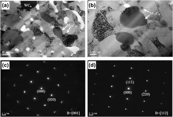
The typical microstructures of the laser clad Co–Cr–W alloy at different magnifications are shown in Fig. 1. As a result of examination of clad layers, the dendritic and directional sub-eutectic structures with an average grain size of 2–4 μm can be observed. The interdendritic eutectic exhibits a network structure. EDS analyses were performed on the clad alloy to determine the chemical compositions of the primary dendrite and interdendritic eutectic, as shown in Table I. It was obvious that the elemental compositions are different as indicated by joint spiders A and B. It can be found that the contents of Co, Fe, and Ni elements are higher in primary dendrite than that in the interdendritic eutectic. There were more C, Cr, and W elements in the interdendritic eutectic structure than in the primary dendrite. Figure 2 shows TEM images and their corresponding SAED patterns of laser clad Co–Cr–W alloy. Similar to the SEM observation, the microstructure consists of dendrite and interdendritic structure with a grain size of 2–4 μm [Figs. 2(a) and 2(b)]. The existence of α-Co solid solution and M23C6 hard phases can be detected by SAED analysis [Figs. 2(c) and 2(d)]. TEM observation indicated the presence of M23C6 in the interdendritic zone. M23C6 is metal rich carbide with a cubic structure, consisting 92 metal and 24 carbon atoms per unit cell with a lattice parameter of about 1.06 nm. It is worthy mentioned that the formation of network eutectic structure often appears in laser solidified microstructures of Fe, Ni, and Co alloy Reference Zielinski, Smolenska, Serbinski, Konczewicz and Klimpel5,Reference Xu, Kutsuna, Liu and Yamada23 and is unfavorable for the comprehensive properties. The following studies focus on the microstructural modification of Co–Cr–W via FSP.
SEM images showing typical microstructures of the laser cladding Co–Cr–W alloy.

Element atomic concentration for microstructures indicated in Fig. 1 by EDS analyses.

TEM bright-field images (a), (b) of laser-clad alloy and their corresponding SAED patterns of (c) α-Co, and (d) M23C6.

B. Nanostructured surface layer fabricated by FSP on laser Co–Cr–W coating
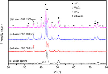
Figure 3 shows the XRD patterns of the laser clad Co–Cr–W alloy layer before and after FSP at various rotary speeds. The main phase constituent of the as-received laser cladding Co–Cr–W alloy was found to be α-Co solution and M(Cr, Fe)23C6 [Fig. 3(a)]. The chemical composition analysis measured by EDS supports the XRD results as listed in Table I. It confirms that the interdendritic zone is rich of carbides in the laser solidified microstructure. After FSP, the primary α-Co and M23C6 phases were retained in the FSPed Co–Cr–W layer regardless of the FSP rotary speeds. However, at a FSP rotary speed of 300 rpm, the WC x new phase emerged in the FSPed Co–Cr–W layer [Fig. 3(b)]. When FSP rotary speeds increased to 900–1500 rpm, Co3W3C and WC x new phases were observed [Figs. 3(c) and 3(d)].
XRD patterns of the laser clad Co–Cr–W alloy layer before and after FSP with various rotary speeds.

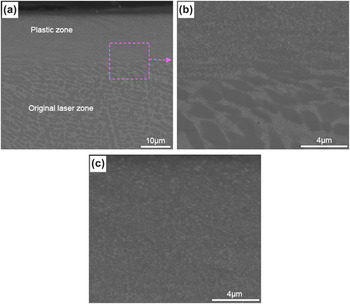
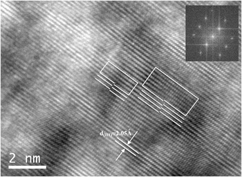
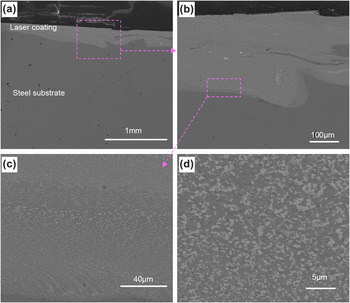
Figure 4 shows the SEM images taken from the cross-section of Co–Cr–W alloy layer after FSP at a rotary speed of 300 rpm. As similar to recent reports in the FSP-treated layer, three typical regions can be recognized as plastic region, thermomechanical region, and original laser solidification region. Reference Li, Yuan and Qiu20,Reference Dehghani and Chabok24,Reference Chabok and Dehghani25 The plastic region at the top surface was stirred by a high rotary tool and subjected to severest plastic deformation, resulting in nanograins, thus no network carbides and dendritic grains were observed in the FSP plastic zone. The thermomechanical effect region between the plastic region and original laser solidification microstructure undergone the friction stress and friction heating which were relatively lower compared with the plastic region. Original laser solidification region beneath the thermomechanical effect region was not influenced by the FSP and kept original dendritic microstructure. To further confirm the nanocrystalline, FIB-TEM was performed to identify the nanograin at the plastic region, as presented in Fig. 5. Similar to SEM observation, the coarse dendritic microstructure with an average grain size of 2–4 μm was transformed into nanograin with an average grain size of about 50–200 nm, although a certain number of coarse grains above 200 nm were present [Figs. 5(a) and 5(b)]. Simultaneously, the carbides in network eutectic were crushed into dispersed nanoparticles. A great deal of subgrains and high-density dislocations could also be observed. α-Co and M23C6 phases can be detected in the SAED image [Figs. 5(c) and 5(d)]. HRTEM was then performed to observe the crystal lattice, as shown in Fig. 6, showing the misfit of (111) atomic planes as marked by white lines and the Burgers circuit. It indicated that there existed some partial dislocations and stacking faults in the α-Co solid solution, which revealed the deformation mechanism during FSP. The deformation mode in the present study was similar to Co-base alloys subjected to hot deformation. Reference Yamanaka, Mori and Chiba26 Yamanaka et al. Reference Yamanaka, Mori and Chiba27 pointed out that the Co–Cr–W alloy has low stacking fault energy (SFE) than stainless steel 304SS. The main restoration mechanism during FSP is dynamic recrystallization (DRX). The DRX nucleation and grain fragmentation by SPD contributed the grain refinement during FSP of laser clad Co–Cr–W.
SEM images taken from cross-section of Co–Cr–W alloy layer after FSP with a rotary speed of 300 rpm: (a) comparison of plastic and original laser zones; (b) high magnification of (a) showing the interface of nanograin and network microstructure; and (c) high magnification of (a) showing the nanograin in the plastic zone.

FIB-TEM bright-field images (a), (b) of FSPed nanostructured Co–Cr–W surface layer processed at a rotary speed of 300 rpm and their corresponding SAED patterns of (c) α-Co, (d) M23C6.

HRTEM image of the (111) atomic plane of α-Co and a Burgers circuit, indicating a partial dislocation connecting with the stacking fault.

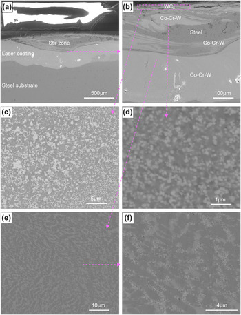
When a relatively higher FSP rotary speed of 900 rpm was applied, a different microstructure evolution from the lower rotary speed of 300 rpm is present in Fig. 7. The microstructures at a rotary speed of 900 rpm possessed a visible stir zone consisting of complex spirals and vortex-like although there was no probe in stir tool which could plunge into Co–Cr–W layer inner [Fig. 7(a)], while FSP at 300 rpm could not produce stir zone with only a thin plastic zone. In the stir zone, the coarse eutectic structure Co–Cr–W alloys solidified by a laser were broken into refined microstructure, with detectable plastic deformation and trances of plastic flow. A high magnification of Fig. 7(a) showed the complex material flow [Fig. 7(b)]. The EDS analysis revealed that the stir zone contains WC x , steel and Co–Cr–W alloy, as clearly marked in Fig. 7(b). The top surface was rich in WC x particles, since the wear debris of WC–Co stir tool was squeezed into the Co–Cr–W coating and homogenously reserved at the top surface [Figs. 7(b) and 7(c)]. Beneath the WC x top surface, the vortex-like mixtures of Co–Cr–W alloy and steel can be clearly observed. Combining the analysis of flow traces, it can be found that during FSP the partial Co–Cr–W coating was pushed downwards and squeezed into the steel substrate. Simultaneously, the partial steel substrate was pushed upward and mixed with Co–Cr–W alloy. The high magnification of Co–Cr–W alloy in the stir zone is shown in Fig. 7(d), revealing that many carbide nanoparticles with an average size below 200 nm uniformly dispersed in α-Co matrix, which was similar to the plastic zone at a rotary speed of 300 rpm [Fig. 4(c)]. Beneath the stir zone, the network and eutectic microstructures were also crushed into homogeneously distributed particles with sub micrometer/nanometer scales [Figs. 7(e) and 7(f)]. On the whole, when a higher rotary speed of 900 rpm was applied, a vortex-like stir zone with a depth of about 500 μm consisting steel and Co–Cr–W alloy was formed, which was different from the microstructures processed at a rotary speed of 300 rpm with only a thin plastic zone with a thickness of 25 μm.
SEM images taken from the cross-section of Co–Cr–W alloy layer after FSP with a rotary speed of 900 rpm: (a) low magnification showing the stir zone, coating, and substrate; (b) high magnification of (a); (c) high magnification of (b) showing the WC x phase in the top surface; (d) high magnification of (b) showing the nanograin of Co–Cr–W alloy; (e) high magnification of (b) showing beneath the stir zone; and (f) high magnification of (e).

With further increase in the rotary speed to 1500 rpm, the Co–Cr–W coating was fully subjected to SPD and co-deformed with steel substrate, as evidenced in Fig. 8. Similar to the microstructures at rotary speeds of 300 and 900 rpm, the coarse eutectic microstructures were broken into dispersive nanoparticles in the plastic zone. However, the microstructure evolution at a rotary speed of 1500 rpm showed obvious differences from 300 and 900 rpm that the whole laser clad coating undergone plastic deformation, thus the whole coating layer was transformed into nanostructure. More interestingly, an interlocking bonding between the Co–Cr–W coating and steel substrate was formed, which was favorable for the connection between coating and substrate. The rapid FSP rotary speed 1500 rpm yielded a very high strain ratio and influenced the substrate, thus the Co–Cr–W layer and steel substrate were co-deformed, forming the interlocking bonding.
SEM images taken from the cross-section of Co–Cr–W alloy layer after FSP with a rotary speed of 1500 rpm: (a) low magnification showing interlocking bonding between coating and substrate; (b) high magnification of (a); (c) high magnification of (b) showing the nanograins; and (d) high magnification of (c).

During FSP Co–Cr–W alloy, the rotary tool produces elevated temperature and SPD within a very short period of time, the as-crushed nanostructured α-Co and carbide grains have limited time for grain growth, thus forming nanostructured Co–Cr–W coating. Moreover, the as-produced dispersive nanoparticles dragged the grain boundary migration and thus the grain growth was kinetically hindered. Expect for the modification of laser coating, FSP may also be an ideal approach to modify metallurgical defects of laser additive manufacturing, such as selective laser melting (SLM) and laser engineering net shaping (LENS). In all, it is suggested that FSP on laser cladding Co–Cr–W coating can provide (i) SPD, which can not only refine the α-Co solid solution, but also crush the carbide in network eutectic into homogeneously distributed nanoparticles, thereby forming nanostructure Co–Cr–W coating layer on steel substrate, (ii) WC x reinforced Co–Cr–W alloy surface layer, owing to the wear of WC–Co tool and enter into Co–Cr–W layer, and (iii) interlocking bonding with steel substrate, which is favorable for the connection between coating and substrate.
C. Effect of FSP on microhardness and wear behavior of Co–Cr–W coating
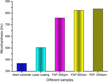
The microhardness for Co–Cr–W coatings before and after FSP and substrate is shown in Fig. 9. It is obvious that the hardness enhanced from 368 Hv of steel substrate to 503 Hv of laser clad Co–Cr–W coating. When FSP was applied on Co–Cr–W coating, generally, the hardness increased significantly to 750–836 Hv. Moreover, a higher rotary speed can produce a higher hardness. The main strengthening mechanisms in the present study include fine grain strengthening, work hardening, second phase strengthening, and dispersion strengthening.
The microhardnesses for Co–Cr–W coatings before and after FSP and substrate.

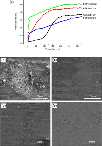
Figure 10 illustrates the friction coefficient variations with time and typical morphologies of the worn surfaces of the Co–Cr–W coatings before and after FSP. Although the friction coefficients of each sample showed slight fluctuations, the applied rotary speeds played a key role in influencing friction coefficients [Fig. 10(a)]. The friction coefficient of laser clad Co–Cr–W alloy was about 0.45. The worn surface showed groove, local exfoliation, and fragments with visible inner dendritic microstructure [Fig. 10(b)], indicating the weaker wear property. When a low FSP rotary speed of 300 rpm was applied, the friction coefficient of FSP-treated Co–Cr–W alloy layer decreased compared with Co–Cr–W coating without FSP. The worn surface became smooth compared with that without FSP, although the worn surface showed some small shallower grooves without any visible material exfoliation and fragment, showing better wear behavior [Fig. 10(c)]. Nevertheless, as a high FSP rotary speed of 900 rpm was applied, the friction coefficient of FSP-treated alloy layer increased to about 0.55 and was higher than the original laser clad Co–Cr–W coating. The worn surface became smoother and almost no apparent grooves can be observed [Fig. 10(d)]. With the further increase of FSP rotary speed to 1500 rpm, the friction coefficient increased to about 0.6. The worn surface turned to much smoother than that at lower rotary speed [Fig. 6(e)]. It can be seen that, with the increase of rotary speed, the friction coefficient of FSP-treated decreases at initial stage and then increases. The phenomenon can be explained as follows. At a lower FSP rotary speed of 300 rpm, the top surface after FSP is nanocrystalline Co–Cr–W alloy, which possesses lower friction coefficient. When the higher FSP rotary speeds are applied, the top surfaces of as-received coatings are WC x –Co thin layers, which came from WC–Co stir tool due to the tool abrasion. Due to the different materials at the top surface of coatings, the friction coefficients at a rotary speed of 900–1500 rpm are higher than rotary speed 300 rpm and original laser clad Co–Cr–W alloy. The friction coefficient tests at different FSP rotary speeds are in accordance with the above XRD and SEM results.
Friction coefficients of Co–Cr–W alloy coatings at different processing conditions (a). SEM images showing morphologies worn surfaces: (b) laser-clad original coating, (c) FSP 300 rpm; (d) FSP 900 rpm; and (e) FSP 1500 rpm.

IV. CONCLUSIONS
The fabrication process of the nanostructured Co–Cr–W layer by the laser cladding and the FSP was studied. The obtained results can be summarized as follows:
-
(1) Laser solidified Co–Cr–W alloy coating has dendritic and sub-eutectic microstructures with an average grain size of 2–4 μm. The interdendritic eutectic formed a network structure and was rich in carbides. The main phase constituents of laser cladding Co–Cr–W alloy were found to be α-Co and M(Cr, Fe)23C6. After FSP, new phases WC x and Co3W3C appeared except the primary α-Co and M23C6 phases.
-
(2) The nanostructured Co–Cr–W surface layer can be formed by FSP on laser clad layer. At a FSP rotary speed of 300 rpm, the coarse dendritic microstructure (grain size: 2–4 μm) was transformed into nanograin (grain size: 50–200 nm) with plastic zone thickness of 25 μm. Moreover, the network carbides were crushed into dispersive nanoparticles homogeneously distributed in α-Co matrix. When a higher rotary speed of 900 rpm was applied, a WC-rich thin layer was formed on the top surface, because the abrasive WC particles from stir tool were squeezed into the Co–Cr–W coating. Beneath the WC x surface thin layer, a vortex-like stir zone with a depth of about 500 μm consisting nanostructured steel and Co–Cr–W alloy was obtained. With further increase of rotary speed to 1500 rpm, the whole coating plastically deformed to nanostructure with an interlocking bonding with the steel substrate, which was beneficial to the connection between coating and substrate. FSP at a rotary speed of 1500 rpm is suitable for fabricating thick nanostructured Co–Cr–W layer with interlocking bonding.
-
(3) The nanostructured Co–Cr–W alloy by FSP has a high hardness of about 836 Hv, which is much higher than that of laser clad Co–Cr–W alloy with hardness about 503 Hv. After FSP, with the increase of rotary speed, the friction coefficient of FSP-treated decreases first and then increases.
ACKNOWLEDGMENTS
The authors wish to acknowledge the financial support of National Natural Science Foundation of China (51101126, 51301028, 51301205, 51405288), Open found of State Key Laboratory of Material Processing and Die & Mold Technology (P2014-07), Changzhou Scientific and Technological Projects (CJ20130034) and Pecialized Research Fund for the Doctoral Program of Higher Education of China (20130162120001).