1. INTRODUCTION
As pointed out in Vermaas's position paper in this Special Issue and in survey papers (e.g., Perlman, Reference Perlman2004; Wouters, Reference Wouters2005; Erden et al., Reference Erden, Komoto, Van Beek, D'Amelio, Echavarria and Tomiyama2008), although much research has been carried out on the definition of function in several research areas, such as engineering design (Hubka & Eder, Reference Hubka and Eder1988; Pahl & Beitz, Reference Pahl and Beitz1996; Umeda et al., Reference Umeda, Ishii, Yoshioka, Shimomura and Tomiyama1996; Hirtz et al., Reference Hirtz, Stone, McAdams, Szykman and Wood2002), artificial intelligence (Goel, Reference Goel, Brown, Waldron and Yoshikawa1992; Lind, Reference Lind1994; Sasajima et al., Reference Sasajima, Kitamura, Ikeda and Mizoguchi1995; Chandrasekaran & Josephson, Reference Chandrasekaran and Josephson2000), philosophy (Cummins, Reference Cummins1975; Johansson et al., Reference Johansson, Smith, Munn, Tsikolia, Elsner, Ernst and Siebert2005; Dipert, Reference Dipert2006; Vermaas & Houkes, Reference Vermaas and Houkes2006), and ontology research (Kitamura et al., Reference Kitamura, Sano, Namba and Mizoguchi2002, Reference Kitamura, Koji and Mizoguchi2006; Arp & Smith, Reference Arp and Smith2008; Borgo et al., Reference Borgo, Mizoguchi and Smith2011), there is no common definition of function, and the relationships among the proposed definitions remain unclear.
The authors have been involved in ontological modeling of function for over 15 years. We have proposed an ontological definition of function (Sasajima et al., Reference Sasajima, Kitamura, Ikeda and Mizoguchi1995; Kitamura et al., Reference Kitamura, Sano, Namba and Mizoguchi2002, Reference Kitamura, Koji and Mizoguchi2006) as an instance of the revisionary approach discussed in Vermaas's (Reference Vermaas2013) position paper. We have also established a taxonomy of function as a hierarchy of functional concepts in the form of transitive verbs, called a functional concept ontology (Kitamura et al., Reference Kitamura, Sano, Namba and Mizoguchi2002).
Since then, its modeling framework has been deployed in industry (Kitamura et al., Reference Kitamura, Kashiwase, Fuse and Mizoguchi2004, Reference Kitamura, Koji and Mizoguchi2006). Although the practical deployment has been successful, achieving real benefits in daily engineering activities, we have been faced with some of the same difficulties and practical expressions of function reported in Eckert's (Reference Eckert2013) position paper. In practice, engineers tend to describe functions of artifacts without a clear definition of function in an ad hoc manner. As a result, the function of a certain artifact is described differently by different engineers. For example, the function of an electric fan can be variously represented as “to move air,” “to cool the human body,” or “to make people comfortable.” Such inconsistency makes it difficult to share and reuse functional models.
This practical experience was the motivation for us to propose a reference ontology of function (Kitamura et al., Reference Kitamura, Takafuji and Mizoguchi2007; Mizoguchi & Kitamura, Reference Mizoguchi and Kitamura2009), which categorizes other existing definitions of functions and practical expressions, including our definition of function. Its aim is to harmonize different definitions and practical expressions of functions with clear relationships. It can be regarded as an instance of Vermaas's (Reference Vermaas2013) overarching approach. With a clear understanding of the relationships among the definitions and practical expressions, we can find the commonalities and differences among them. This will contribute toward providing engineers with some clearly differentiated definitions and expressions for consistent functional modeling and will contribute to interoperability as well. In addition, we have investigated different kinds of function in a phase-oriented model along the product life cycle (Kitamura & Mizoguchi, Reference Kitamura and Mizoguchi2009, Reference Kitamura and Mizoguchi2010).
In this paper, as a response to the position papers mentioned above (Eckert, Reference Eckert2013; Vermaas, Reference Vermaas2013), we explain our methodology for the reference ontology and for the phase-oriented model for accommodating and differentiating the existing definitions and practical expressions of function, especially those used in engineering practice.
The core idea of our methodology is that one of the causes of the differences among them is the difference of perspectives for capturing function. When one captures the function of a certain entity, one focuses on a specific aspect of the entity from a specific perspective. For example, the three functions of an electric fan mentioned above can be explained in terms of the differences of the causal scopes on which the engineers focus for capturing the function, as discussed later. Such causal scope is one of the kinds of perspectives that we want to identify here. We call such a perspective the capturing perspective in this paper.
In this paper, we discuss various kinds of perspectives for capturing functions, illustrated with examples. We show that such perspectives can explain some of the examples reported in Eckert (Reference Eckert2013). The reference ontology and the phase-oriented model are intuitively based on such perspectives but do not explicate them. Thus, in this paper, we try to conceptualize the rationale behind them, which is implicit in our previous papers, as kinds of perspectives for capturing functions.
In addition, as a response to Eckert (Reference Eckert2013), based on our experiences gained in practical deployment (Kitamura et al., Reference Kitamura, Kashiwase, Fuse and Mizoguchi2004, Reference Kitamura, Koji and Mizoguchi2006), we report some solutions, such as modeling guidelines, for overcoming some of the difficulties faced in practical functional modeling pointed out by Eckert (Reference Eckert2013). We have shown that such solutions help engineers describe functional models based on a single ontological definition of function and will be beneficial for functional modeling in industry.
This paper is organized as follows. Section 2 discusses various kinds of perspectives for capturing functions. In Section 3, we explain the examples of the functions reported in Eckert (Reference Eckert2013), using the kinds of perspectives identified in Section 2. Then, we suggest some appropriate perspectives for capturing functions from the viewpoint of composability. Section 4 reports some practical solutions found in our deployment, which contribute to consistent functional modeling based on a stable perspective. Section 5 gives some concluding remarks.
2. PERSPECTIVES FOR CAPTURING FUNCTIONS
2.1. Causal scope
When an entity performs a function, there are changes of values of physical (or mental) attributes. The changes form so-called causal chains. In the example of an electric fan used in the usual way (i.e., a fan supplied with electricity and pointing toward a person), when the fan is working properly, there is the following causal chain:
1. to rotate the fan blades,
2. to move air in front of the fan,
3. to move air around the person,
4. to promote evaporation of water at his/her skin,
5. to cool the skin, and
6. to make him/her comfortable.
The causal scope, as a kind of capturing perspective, represents which change in a causal chain like the above is focused on. When one focuses on a specific change in a causal chain for capturing the function of an entity, it implies that one focuses on the scope of the location of that change, which extends from the location of the entity to the location of that change.
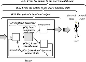
In the following subsections, we discuss some kinds of causal scope perspectives. The relationships among them are shown in Figure 1. We give an ID code (C#) to each kind, where C represents a causal scope perspective and # represents an ID number based on the extent of the scope, which does not correspond to one of the causal point numbers above.
The kinds of causal scope perspectives. [A color version of this figure can be viewed online at http://journals.cambridge.org/aie]

The causal scope perspectives are categorized into C1 to C5. We can make a distinction between C1 and C2, on the one hand, and C3 to C5, on the other hand, based on the notion of a “system boundary,” which is the interface between the whole system and an intentional agent (called an end user or just a user). By the whole system, here we mean the system that is composed of subsystems and/or components (based on the so-called device ontology; Mizoguchi & Kitamura, Reference Mizoguchi and Kitamura2009), that is the largest and outermost device that has an interface to an end user, and that is directly operated by the end user for his/hers purpose. The effect achieved by the whole system on the user is categorized into one of C3 to C5, as explained in Section 2.1.1, and is called an external function, as discussed in Section 2.1.2. The effect achieved by components within the whole system is categorized as C1 (C1-1 and C1-2) or C2 and is called the component function, which is discussed in Section 2.1.3. In the following subsection, we first explain C3 to C5 based on the notion of the system boundary.
2.1.1. System boundary
Based on the notion of the system boundary discussed above, we can identify the following three kinds of causal scope perspectives:
C3. The system's input and output: The example is “to move air” in the case of the electric fan. This focuses on the causal change (2) and thus focuses on the airflow at the fan's input and output as locations. Those who capture this function as a function of the fan regard the fan as a black box system and focus on the system's direct input and output only within the system boundary in terms of location.
C4. From the system to the user's physical state: Consider the example “to cool the human body.” This focuses on the causal change (5), which is not a direct result of the fan but involves other phenomena around the user. In other words, the focal causal scope extends to the user, outside of the system boundary.
C5. From the system to the user's mental state: Consider the example “to make him/her comfortable.” This focuses on the causal point (6) and refers to a person's cognitive mental state (i.e., to feel comfortable). The causal scope extends to the user's mental state, outside of the system boundary.
In the reference ontology, these functions are categorized as a device function, a physical environmental function, and an interpretative function, respectively, though these kinds of perspectives were left implicit (Kitamura et al., Reference Kitamura, Takafuji and Mizoguchi2007).
Some researchers have pointed out similar distinctions. The environment function (Chandrasekaran & Josephson, Reference Chandrasekaran and Josephson2000), which is an effect on the environment, is similar to ours from the (C4) perspective. Goel (Reference Goel2013) points out the necessity for “multiple perspectives on a system” for this distinction as Principle 11. Some researchers distinguish purpose from function (e.g., Hubka & Eder, Reference Hubka and Eder1988; Lind, Reference Lind1994; Gero & Kannengiesser, Reference Gero and Kannengiesser2002), where the purpose represents a human-intended goal in a similar sense to perspective (C4) or (C5). Dipert (Reference Dipert2006) points out such goal dependence with respect to some agent and a level of description as well.
2.1.2. Component and external system
From the perspective of the causal scopes within the system, we can distinguish between a component function and an external function (Kitamura & Mizoguchi, Reference Kitamura and Mizoguchi2010) based on the notion of the system boundary discussed in Section 2.1. The causal point (1) in the causal chain of the fan represents a component function of a motor, which is a component embedded in the fan and contributes to the functioning of the fan as the whole system. In short, the component function performed by a component contributes to the achievement of the goal determined by the whole (or the smallest larger sub-) system, whereas the external function performed by the whole system contributes to the achievement of the goal directly determined by the user's intention.
Therefore, the kinds of causal scope perspectives include (C1) the local component for the component function as well. The external function can be explained by the kind (C3) the (whole) system's input and output discussed above. We will use these kinds of function in Section 2.5.
2.1.3. Locality of component function
The perspective (C1) local component should be investigated further. For example, let us consider a two-port fluid valve called a “flow-control valve.” When the input signal to the valve is changed by a controller (or a user), the fluid flow rate (i.e., the amount of fluid that flows in a given time) is changed. Therefore, many people would describe its component functions as “to change the fluid flow rate.” However, this is not truly “local” but is dependent on components in the fluid system, such as a pump. We believe a truly local function is, “to change the difference between the pressure at the input port and that at the output port.” The reason for this is that the causal chain for changing the flow rate is as follows:
1. When one changes the control signal to the valve for decreasing the flow rate, the area where fluid flows is narrowed by a disc.
2. The difference between the pressure at the input port and that at the output port of the valve increases.
3. If the pump in the system is a variable-flow type (a so-called variable displacement pump) with a controller that regulates the flow rate according to the pressure of the total load, the pump decreases the flow rate at its outlet.
4. The flow rate through the valve decreases.
The changing the flow rate function refers to change (4) and is thus dependent on the type (and/or on the control) of the pump at change (3).
In the case of a positive (fixed) displacement pump, in contrast, the pump outputs a fluid at a fixed flow rate; hence, the flow-control valve itself cannot reduce the flow rate of the fluidFootnote 1 and so just the flow speed at the valve increases. Anyway, the changing the flow rate function is dependent on the other components.
In addition, the same valve is sometimes called a “level-control valve.” It is also dependent on other components, such as a tank, as well as the system configuration. A couple of assumptions are needed, such as the tank is located upstream of the valve (without any branch) and the input flow rate to the tank is stable to some extent, and hence the level of fluid contained in the tank is controlled by the output flow rate of the tank. Thus, this function is not local either.
Based on the observation above, we can distinguish the following three additional kinds of causal scope perspectives with the example of a flow-control valve:
C1-1. Local causal chain: The entire causal chain is within the component. It depends only on conditions regarding the local inputs and refers to the change at the output port. Example: “to change the pressure difference.”
C1-2. Nonlocal causal chain: The expression itself is local (i.e., a subtype of C1). Part of the causal chain, however, includes the change at another component in the system. Therefore, it depends on another component and/or the system configuration. Example: “to change the flow rate.”
C2. Nonlocal reference: The expression itself refers to another component (e.g., “to change the level”). This is not from the (C1) local component perspective but is from a perspective inside the system, unlike (C3) the system's input and output perspective.
Note that the (C1-1) local causal chain perspective has local conditions (assumption or dependence) for working properly (e.g., the existence of fluid at the input port). We discuss here the causal locality of such conditions.Footnote 2 This causal locality is very important for composability of the component models, as discussed in Section 3.2.
2.2. Temporal aspect
A (discrete) change of an attribute of an entity can be captured as a difference of its values from time point t 1 to time point t 2. In other words, here we are concerned with the time interval from t 1 to t 2. The same type of changes can imply different meanings for different phases/stages of the time intervals. For example, when one describes the function of a heater as “a heater increase the temperature,” it can imply:
• “A heater increases the temperature of the air at a specific location in a room compared with a previous point in time.”: This refers to the change in the air temperature at a specific absolute location in real time, which is the same sense as in computer-based numerical simulation.
• “A heater increases the temperature of the air at the output port to a higher temperature than at the input port.”: This refers to the change in the air temperature while the air flows from the input port to the output port of the heater. Precisely, this change represents the difference in temperature during the time interval from t 1 to t 2, where a specific amount of air flows at the input port at time point t 1 and the same amount of air flows at the output port at time point t 2. These time points are specified relatively with respect to the operating device.
• “In comparison with the original design, the redesign of the heater increases the highest temperature of the air.”: This refers to the change in the highest temperature of the air between time point t 1 at the original design and time point t 2 after redesigning the heater.
Thus, there are three kinds of temporal aspect perspective: absolute functioning time (T1), flowing-object functioning time (T2), and designing time (T3). Footnote 3 Note that many engineers use just “a heater increases the temperature,” unaware of these differences. As discussed in Section 2.5, from the viewpoint of the product life cycle phase, (T1) and (T2) correspond to (P5), whereas (T3) refers to a different product life cycle phase where t 1 and t 2 correspond to (P1) and (P2), respectively. Nevertheless, in our industrial deployment, we found many such expressions that can be categorized into (T3). For instance, consider the function of diamond powder in a cutting machine. The function can be expressed as the following:
• “The diamond powder increases the frictional coefficient of the cutting blade”: When the cutting machine is functioning, the frictional coefficient is kept high and does not increase while working. The increase refers not to a change in functioning time but to a comparison between two design cases with and without the diamond powder. We will revisit this example in Section 4.2.
This illustrates the need for a temporal aspect as a kind of perspective for capturing function.
2.3. Material–energy–information level
A physical change can be captured at the material level or at the energy level, and some attributes can be interpreted as information. Therefore, we can identify three levels as kinds of perspectives: (L1) material level, (L2) energy level, and (L3) information level. For example, the function of an electric motor can be captured as either “to rotate a shaft” from the (L1) material level perspective or “to convert electrical energy to mechanical (rotational) energy” from the (L2) energy level perspective.
Similarly, multilevel flow modeling (Lind, Reference Lind1994) treats functions of energy, mass, action, and information, and functional basis (Hirtz et al., Reference Hirtz, Stone, McAdams, Szykman and Wood2002) has taxonomies of energy and material.
2.4. Intentional aspect
The function of an artifact is usually regarded as one tightly related to the intention of the designer or user. When the artifact is working, there might be other phenomena (causal chains) that are unintended by the designer and/or user, such as a so-called side effect. In addition, one can imagine possible unintended phenomena such as faults and abnormal behaviors. To avoid the negative influence of such unintended phenomena in the normal functioning processes of the system, there might be a function either to prevent such unintended phenomena or to stop (or compensate for) the influences of the unintended phenomena. In our extended theory (Kitamura et al., Reference Kitamura, Koji and Mizoguchi2011), we can capture unintended phenomena based on the same modeling methodology. Therefore, from the intentional aspect, we can identify the following kinds of perspectives: (N1) functioning process, (N2) unintended phenomenon, (N3) preventing process, and (N4) compensating process.
For example, one possible causal chain in an electrical circuit from the (N2) unintended phenomenon perspective is “a device1 generates heat,” “the heat propagates to another device2,” “device2's temperature exceeds its allowable limit,” and then “device2 malfunctions due to overheating.” To prevent this, the circuit might include a current-controller for device1 that controls the current according to the temperature of device2. From the (N3) preventing process perspective, its function can be captured as “to prevent the generation of excessive heat by device1.” The circuit might also include an electric fan for cooling device2. From the (N4) compensating process perspective, its function can be captured as “to compensate for the heat” to prevent it influencing device2.
Note that there are many preventing and compensating processes in practical machines, and it is impossible to enumerate all such processes in advance. In practical modeling, only the processes focused on by the designer are described. In addition, by “unintended phenomena,” we mean phenomena that are not intended by the designer, although other designers or users might intend such phenomena.Footnote 4 Furthermore, “unintended phenomena” and “malfunctioning” are different notions. All malfunctions are unintended phenomena but not vice versa. Many unintended phenomena have no relationship with function (i.e, not harmful to the functioning but merely side effects).
The practical needs for clearly modeling such processes are pointed out in Section 5 in Eckert (Reference Eckert2013) as well. Together with colleagues, we have developed an extended modeling framework that can represent all these phenomena and their relationships depicted in three-dimensional space (Kitamura et al., Reference Kitamura, Koji and Mizoguchi2011).
2.5. Product life cycle phases
An engineering product has phases in its product life cycle in which transitions are caused by engineering acts such as design, manufacturing, and use. Function is captured in different ways according to the phases focused on. We have explained different kinds of function in such product life cycle phases (Kitamura & Mizoguchi, Reference Kitamura and Mizoguchi2009, Reference Kitamura and Mizoguchi2010). Here, we briefly describe some of the results. In the phases related to use and manufacturing of a product (an entity), we can distinguish the following two functions:
• During the actual use phase (working phase): When the entity is actually used by an agent (a user), actual functions are performed. Precisely speaking, in our theory (Kitamura et al., Reference Kitamura, Koji and Mizoguchi2006), an actual function is a role played by a behavior as a process under a specific context (of use).Footnote 5 Therefore, it occurs in the use phase, exists outside the entity, and is dependent on context (of use). This perspective is called (P5) actual use phase. Footnote 6
• After-manufacturing phase (come-into-existence phase): As a result of manufacturing the entity, the entity has a capacity to realize specific behaviors based on its physical makeup. One of the behaviors could play an actual function as a role according to the context of use. We call the capacity of a behavior to become a function a capacity function. It represents a capacity to perform an actual function, which is potential and hidden. This perspective is called (P3) after-manufacturing phase.
These two kinds of function can explain the difference between many definitions in engineering and those in philosophy. In many definitions in engineering (e.g., Lind, Reference Lind1994; Sasajima et al., Reference Sasajima, Kitamura, Ikeda and Mizoguchi1995; Pahl & Beitz, Reference Pahl and Beitz1996; Umeda et al., Reference Umeda, Ishii, Yoshioka, Shimomura and Tomiyama1996; Hirtz et al., Reference Hirtz, Stone, McAdams, Szykman and Wood2002; Kitamura et al. Reference Kitamura, Koji and Mizoguchi2006), a function is directly related to a process performed by an artifact when the artifact is used. For example, Umeda et al. (Reference Umeda, Ishii, Yoshioka, Shimomura and Tomiyama1996) define a function as “a description of behavior abstracted by a human through recognition of the behavior in order to utilize it.” Therefore, it corresponds to the actual function.
In contrast, in many definitions in philosophy, a function is a special feature of an artifact (Perlman, Reference Perlman2004) and what the artifact has or what is ascribed to the artifact. For example, in causal-role function analysis (Cummins, Reference Cummins1975) and intention/cause/evolution theory (Vermaas & Houkes, Reference Vermaas and Houkes2006), a technical (artifact) function is regarded as a special kind of capacity to be ascribed to an artifact. Thus, it corresponds to a capacity function.
Arp and Smith (Reference Arp and Smith2008) propose a sophisticated definition of artifact function under a generic definition of functions, including biological functions. This definition regards function as a realizable entity (“realizable dependent continuant”), which is similar to a capacity function and includes the component function only. The reader is referred to Kitamura and Mizoguchi (Reference Kitamura and Mizoguchi2010) for details and more explanation.
2.6. Summary
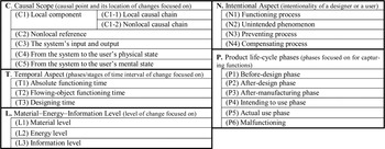
Figure 2 shows a summary of the perspectives discussed thus far. These perspectives are, in principle, orthogonal to each other. However, there are some exceptions: (T1) and (T2) are related to (P5), and (T3) is related to (P1) and (P2).
Summary of the kinds of capturing perspectives discussed in Section 2.

3. DISCUSSION
3.1. Explanation of the Eckert examples
In this section, we try to explain the examples of the functions of a hydraulic pump shown by Eckert (Reference Eckert2013). The pump is an axial-piston pump “used in off-road vehicles for lifting or moving heavy parts” (Eckert, Reference Eckert2013). It has a rotational shaft that is connected to an external (electric) motor. It has an inlet port and an outlet port for oil. According to Eckert (Reference Eckert2013), “All subjects agreed that the main function of the pump was pumping the oil.” However, “Two subjects mentioned that the pump could also be a motor that ‘transforms the flow of oil into a rotation.’ ” This is very true, as discussed below.
1. “Pumping the oil”: As mentioned above, precisely speaking, this is dependent on the usage of this device whereby the shaft torque is its input and the outlet oil is its intended output. When we call this device a “pump,” this usage is implied. If we can ignore this dependence, this function is basically from the following perspectives: (C1-1) local causal chain, (T2) flowing-object functioning time, (L1) material level, (N1) functioning process, and (P5) actual use phase. This, however, does not mention the pressure of the oil. The relationship among the flow rate, the pressure at the output port, and the power (torque) is dependent on the type of pump and/or the controller, similarly to the flow-control valve discussed in Section 2.1.3. In the case of a so-called positive displacement pump, it outputs fluid at a fixed flow rate. Because the value of the flow rate of the output fluid from the pump is locally determined by the pump, we can say that this is from the (C1-1) local causal chain perspective. In the case of a variable displacement pump with flow-control, however, the flow rate of the output fluid is dependent on the total pressure loss and/or the load of the fluid system. In this case, the function can be regard as coming from the (C1-2) nonlocal causal chain perspective.
2. “Transforms the flow of oil into a rotation”: The rotational torque here is the intended output, and thus this device is a so-called hydraulic motor or actuator. This function is captured from the (C1-1) local causal chain perspective, and thus is truly local. Other perspectives are the same as the above.
In the following, we assume that the hydraulic pump is used not as a motor but as a pump. Based on this assumption, all of the functional expressions shown in Eckert's (Reference Eckert2013) table 2 can be explained as followsFootnote 7:
3. “Convey fluid/oil”: This might imply that the pump conveys the oil to other components. Therefore, this is from the (C2) nonlocal reference perspective. Alternatively, it might imply that the pump conveys the oil from the outlet of the pump to the inlet through the whole fluid circulation system, which could be expressed as “to circulate oil.” This function is from the (C1-2) nonlocal causal chain perspective.
4. “Provide pressure/oil pressure”: This function can be interpreted as either of the following more precise expressions: “to give a certain pressure to the output oil” or “to make a pressure difference between the input and output oil.” The former is not local and is from the (C1-2) nonlocal causal chain perspective, because the value of the output pressure is determined according to the balance of the total pressure loss of the fluid system and the controller. The latter is truly local and can be regarded as one captured from the (C1-1) local causal chain perspective.
5. “Provide oil pressure for the brake system of a lorry”: This is from the (C2) nonlocal reference perspective.
6. “Acceleration of fluid, providing pressure”: This is a combination of expressions (1) and (4).
7. “Convert mechanical into hydraulic energy”: This is from the (L2) energy-level perspective. This is also truly local, from the (C1-1) local causal chain perspective.
8. “Convert mechanical rotation into hydraulic pressure and flow”: This refers to changes in the kind of medium of the power and the kinds of attributes. This is from the (C1-1) local causal chain and the (L1) material-level perspectives.
9. “Convert power”: This is from the (L2) energy-level perspective as well.
10. “Provide a volume flow from A to B”: This is also from the (C2) nonlocal reference perspective.
11. “Providing oil pressure/flow → convert mechanical into hydraulic energy”: This is a combination of expressions (7) and (10).
In summary, the differences among all the expressions reported in Eckert (Reference Eckert2013) can be explained in terms of the kinds of perspectives for capturing functions proposed in this paper. This demonstrates the richness of those kinds of perspectives, though we do not claim that they are exhaustive.
Such explanations of the functions in Eckert (Reference Eckert2013) clarify the reason why each function is described as such, the differences among them, and the reason for the variety of functional expressions for the same pump.
In addition, such differentiation shows an important characteristic, namely, the “locality” of these expressions. Among the expressions above, the truly local ones are (1), (4), (7), (8), and (9), though they are also based on an assumption that the pump is used as a pump. Expressions (7) and (9) are at the energy level. All other expressions depend on the system configuration in some sense.
3.2. Locality and composability
The locality of functional expression is a very important characteristic for knowledge modeling of artifacts as components. It ensures that the model using the expression is dependent only on the component itself and is independent of the system configuration. This enables us to reuse the functional model of the component in any system and is called the “composability” of the model. De Kleer and Brown (Reference De Kleer and Brown1984) note it as the no-function-in-structure principle, which has been regarded as a fundamental principle in the field (Erden et al., Reference Erden, Komoto, Van Beek, D'Amelio, Echavarria and Tomiyama2008). It is implicitly assumed in the function-oriented case-based design (Goel, Reference Goel, Brown, Waldron and Yoshikawa1992) and the repository of component models (e.g., Hirtz et al., Reference Hirtz, Stone, McAdams, Szykman and Wood2002) as well.
On the basis of this observation, at least from the viewpoint of compositional modeling for engineering, the functional expression might be better captured from a single combination of the following perspectives: (C1-1) local causal chain, (T2) flowing-object functioning time, (N1) functioning process, and (P5) actual use phase. Footnote 8 Our definitions of an artifact function and its behavior are captured from these perspectives (Kitamura & Mizoguchi, Reference Kitamura and Mizoguchi2004; Kitamura et al., Reference Kitamura, Koji and Mizoguchi2006).
As reported in Eckert (Reference Eckert2013), it is not an easy task to enforce the use of a definition of function on engineers in practice. We believe, however, that it is not impossible and have found some solutions in our industrial deployment. We briefly report them in the next section.
4. ONTOLOGY-BASED PRACTICAL SOLUTIONS
4.1. A functional modeling framework, its deployment, and practical issues
The authors have established a suite of ontologies as a functional modeling framework of artifacts, which includes a definition of function, behavior, and devices; a taxonomy of function (called a functional concept ontology); and types of functional knowledge (Sasajima et al., Reference Sasajima, Kitamura, Ikeda and Mizoguchi1995; Kitamura et al., Reference Kitamura, Sano, Namba and Mizoguchi2002; Kitamura & Mizoguchi, Reference Kitamura and Mizoguchi2004; Kitamura et al., Reference Kitamura, Koji and Mizoguchi2006). A function is defined as “a result of teleological interpretation of behavior under a goal” (Sasajima et al., Reference Sasajima, Kitamura, Ikeda and Mizoguchi1995), and “a role played by a behavior in a teleological context” (Kitamura et al., Reference Kitamura, Koji and Mizoguchi2006) is defined as an actual function, as discussed before. We have clearly distinguished between a function expressing “what to achieve” and a way of function achievement expressing “how to achieve.” A functional model of an artifact is described as a function decomposition tree, which is a hierarchy consisting of a macro (goal) function and a sequence of micro (method) functions, which achieves the goal function (called an “is-achieved-by” relation) with a way of function achievement as the principle of its achievement.
As mentioned above, our definition of function is a combination of the following perspectives explained in Section 2: (C1-1) local causal chain, (T2) flowing-object functioning time, (N1) functioning process, and (P5) actual use phase. In other words, a function in the model represents a local effect in a component as a difference of states of a flowing object at input and output ports, which is intended by a designer and is supposed to be realized in an actual use phase when appropriate inputs are given under a use context envisioned by the designer. These perspectives are described as part of the guidelines discussed in Section 4.2. Note that “the way of function achievement” above is a different aspect, and this notion is independent of these perspectives.
The modeling framework has been deployed in industry (Kitamura et al., Reference Kitamura, Kashiwase, Fuse and Mizoguchi2004, Reference Kitamura, Koji and Mizoguchi2006). Together with collaborators, we developed software named SOFAST based on the ontological framework. It was successfully deployed in daily work related to production processes. The real benefits include fast and efficient design review, fast patent writing and enhancement of patent claims, improvements in manufacturing machines, and solutions to quality problems (Kitamura et al., Reference Kitamura, Kashiwase, Fuse and Mizoguchi2004, Reference Kitamura, Koji and Mizoguchi2006). The productivity of the production-engineering team increased to 166% in the first year after introducing the methodology and to 211% in the second year.
We faced some practical issues in the deployment (Kitamura et al., Reference Kitamura, Koji and Mizoguchi2006). We mention two of them here. The first issue is how engineers can describe functional models that are compliant with functional ontologies including the definition of function. It is similar to the problem pointed out in Eckert (Reference Eckert2013). The second issue is that it was not easy for engineers to select appropriate functional terms (verbs) from the complex functional concept ontology.
To overcome these difficulties, we have established two extensions to our framework (Kitamura et al., Reference Kitamura, Koji and Mizoguchi2006). One is the establishment of ontological guidelines in order to make ontological commitment easier. The other concerns the treatment of lexical terms for representing functional concepts in order to reduce the difficulty in selecting functional concepts. They are summarized below.
4.2. Ontological guidelines
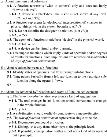
In order to help engineers describe consistent functional models more easily based on ontologies, the authors have established guidelines about functional models (Kitamura et al., Reference Kitamura, Koji and Mizoguchi2006). Part of the guidelines is shown in Figure 3. The guidelines show ontological constraints on the contents of models in the form of a checklist written in a natural language. A model author can check a function decomposition tree using the guidelines and can modify it if necessary. The guidelines are categorized into three groups: α, β, and γ for functions, the relations among subfunctions, and the way of function achievement, respectively. The perspectives discussed in Section 2 are related with “function” and thus correspond to the guidelines in the α group. Some relationships are shown in Figure 3.
A portion of the guidelines for function decomposition trees. Adapted from Kitamura et al. (Reference Kitamura, Koji and Mizoguchi2006) with permission.

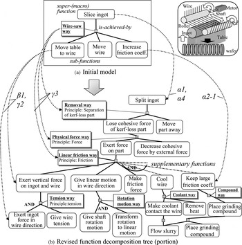
Figure 4 shows an example of a modification process based on the guidelines of the function decomposition tree of a wire-saw, which is a manufacturing machine used to slice semiconductor ingots. Figure 4a shows the initial model and 4b the revised one. In the example, the whole function “to slice” in Figure 4a is modified into “to split” in 4b, because “to slice” implies “how to split,” which is a way of function achievement (a composite way as discussed below). Thus, “to slice” does not follow the guidelines α1 and α4 in Figure 3, and therefore it is modified into “to split apart the ingot,” which enables the designer to select ways other than “slicing.”
A modification of a function decomposition tree of a wire-saw portion. Adapted from Kitamura et al. (Reference Kitamura, Koji and Mizoguchi2006) with permission.

In Figure 4a, “to move table to wire” and “to move wire” are described as sub (method)-functions. However, violating γ2 in Figure 3, the reason why these functions can perform the whole (goal) function is not clear. Moreover, violating β1 in Figure 3, it is unclear which things (called operands) flow between these functions. One reason is that there is a missing function, “to exert vertical force on ingot and wire.” The “to move table to wire” in reality contributes to this function. Therefore, the wire-saw way in Figure 4a should be decomposed into the three ways shown in Figure 4b following γ3.
In addition, the function “to increase frictional coefficient” shown in Figure 4a violates α2-1 from the (T3) designing time perspective. Thus, it is revised to the “to keep large friction coefficient” function in (T2) or (T1), as shown in Figure 4b.
Currently, the guidelines are only for human comprehension. Engineers themselves have to check their models according to the guidelines. Automatic checking for compliance of the functional models with the ontological guidelines using the implemented ontologies is a difficult task and remains the topic of future work.
4.3. Lexical layer
Our experience gained in practical deployment shows the importance of flexible lexical terms for representing functions. Thus, a new version of the software supports four layers of functional terms: an ontology layer, a concept layer, a lexical layer, and a domain-specific layer. The ontology layer is for the full functional concept ontology. The concept layer is a simplified three-level hierarchical version of that ontology for essential functional concepts. The lexical layer includes usual functional words in daily work. The domain-specific layer has vocabulary sets specific to domains or companies. The usual functional words are associated with essential functional concepts. A usual functional word can represent some essential functional concepts and vice versa. For example, the usual functional word “to put together” is associated with the functional concepts “to join” and “to bring into contact.” The function “to bring into contact” can be represented as “to place” as well.
Users can select a function in functional models using either essential functional concepts or usual functional words. When a user selects a usual functional word associated with multiple essential functional concepts, the user has to select one from these candidates to reflect the intended meaning. Thus, a function in models is associated with both a usual functional word and an essential functional concept. Therefore, both the user and the computer can search using essential functional concepts independently of a lexical representation of functions.
5. CONCLUSION
In this paper, as a methodology in the overarching approach for accommodating and explaining the differences among existing definitions and practical expressions, we report our methodology based on perspectives for capturing functions. We proposed several kinds of such perspectives, and in terms of these perspectives, we explained some existing definitions and many practical expressions, including those reported in Eckert (Reference Eckert2013).
Such an overarching approach contributes to interoperability of functional models. We established mappings between our functional ontology and reconciled functional basis (Hirtz et al., Reference Hirtz, Stone, McAdams, Szykman and Wood2002) based on a reference ontology and realized interoperable searching of documents using functional terms in either of these taxonomies (Kitamura et al., Reference Kitamura, Segawa, Sasajima, Tarumi and Mizoguchi2008).
Our main goal here is to enumerate fine-grained perspectives for in-depth understanding of function. We cannot claim their completeness or necessity in nature, however. We demonstrated the usefulness of our framework by showing existing notions of function and practical expressions, including those reported in Eckert (Reference Eckert2013). We note that there might be typical combinations of these perspectives, and an investigation of this remains a topic of future work.
Nevertheless, from the viewpoint of the composability of functional models, we could suggest an appropriate set of perspectives for correctly capturing functions, which our functional ontology is based on.
In addition, we summarized some practical solutions for helping engineers describe functional models that are compliant with a single ontology. On the basis of our experience gained from industrial deployment (Kitamura et al., Reference Kitamura, Kashiwase, Fuse and Mizoguchi2004, Reference Kitamura, Koji and Mizoguchi2006), we can claim that our ontology-based functional modeling framework with these solutions can work well in industry, and engineers can get real benefits from adopting it.
Yoshinobu Kitamura is an Associate Professor of the Institute of Scientific and Industrial Research, Osaka University. He received his bachelor's, master's, and doctoral degrees of engineering in 1991, 1993, and 2000, respectively, from Osaka University. His research interests include ontological engineering, ontology of function and artifacts, ontology-based engineering knowledge management, and conceptual design support.
Riichiro Mizoguchi was a Professor at the Institute of Scientific and Industrial Research, Osaka University, from 1990 to 2012 and is currently a Professor at the Research Center for Service Science, Japan Advanced Institute of Science and Technology. His research interests include knowledge-based systems, theories of role and function, ontological engineering, ontology development, and intelligent learning support systems. Dr. Mizoguchi was president of the International Artificial Intelligence in Education Society and the Asia-Pacific Society for Computers in Education, Vice President of the Semantic Web Science Association, and President of the Japanese Society for Artificial Intelligence. He is currently Associate Editor of IEEE Transactions on Learning Technologies and ACM Transactions on Interactive Intelligent Systems.